Refilling a Kollsman Bubble Chamber – a guest post by Arthur Leung

14 04 2022

Arthur wrote to me in April 2021 with an enquiry about the MHR1 navigational device and then kindly wrote a guest blog about it. He then acquired a Kollsman periscopic sextant and what follows is his account about putting into a working condition, for which I am very grateful.

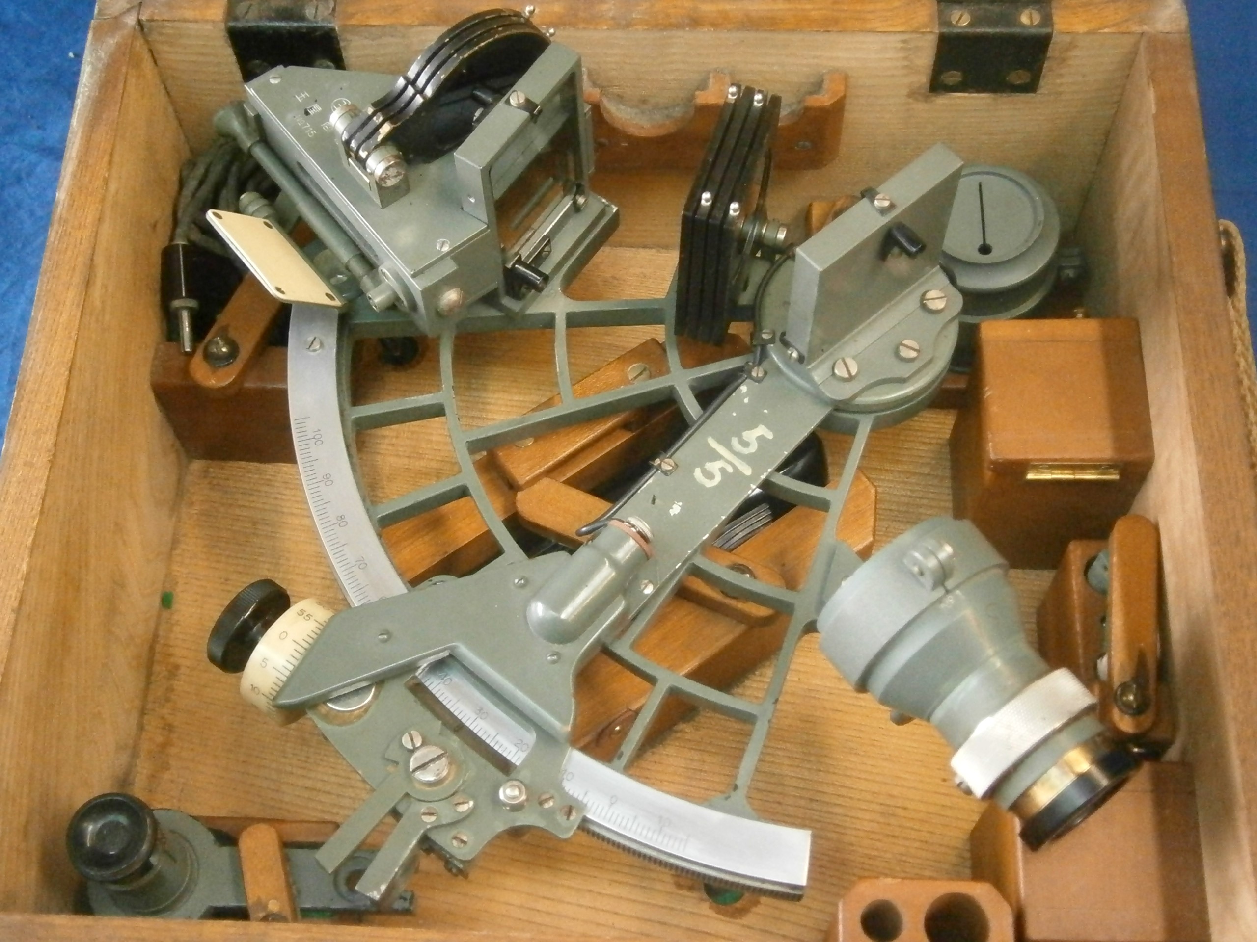
I have been having quite a lot of fun, and a good deal of success, running several Kollsman periscopic sextants.  These instruments are not especially old and are satisfyingly well built.  Of the four instruments that I have examined, I have found them to be in remarkably good working order despite the years in storage.  All four have working clockwork or electronic averagers, operating index systems, and all light bulbs light up.

Of the four, one instrument had a deteriorated pellicle – Bill Morris has an excellent article on this blog that describes how to replace one.  I found that transparency film is a bit easier to work with compared to cling film (food wrap), but the cling film gives a better image.

The thing that appears to be most wrong with these instruments is the sunshade carousel.  Two had dysfunctional carousels which I was not able to fix properly – to make the instruments useable, I took the cover plate off and hand-rotated the shades to the “clear” position to do star sights.

The Kollsman bubbles are surprisingly long lived, with three of the four having survived from their last depot maintenance cycle dating back to at least 1985.  I have some evidence that says that the issue with the one failed bubble chamber has to do with poor material selection rather than a defect in the chamber.

With just a bit of work, however, I was able to get that one dry bubble chamber working again.

Another unit would leak bubbles into the viewing chamber whenever I tried to adjust the bubble size.  With a “topping off” of the fluid, I was able to make that issue disappear.

How I repaired the one dry bubble chamber is described in this article. 

I suspect that there are bubble chambers that have deteriorated over the years beyond where a simple refilling of the chamber can solve the problem – the repair of those units is beyond the scope of this short article.

How to tell if there is a bubble or not

Kollsman periscopic sextants are often found on auction houses like eBay.  It is quite difficult to get most layman sellers to do very much about describing the condition of the instruments they are selling, but there are a few quick ways to determine if there is a working bubble in a particular instrument and both are simple enough that most sellers are able to do them.

The quickest way to tell if there is a bubble or not is to simply set the shade carousel to position “1” and then bring the eyepiece to eye and look to see if there is a bubble.  If there is, it is likely going to be much larger than you want, but if you can see it, this is a good sign and more than likely the bubble can be shrunken using the bubble adjustment knob to a workable size.  Note that this method requires that there be an intact pellicle since the bubble image is brought into the optical path by means of the pellicle – if the bubble is visible in the eyepiece, then good news since the bubble chamber and the pellicle are likely in working order. 

If the bubble is not visible, it may be there but not visible because the pellicle has deteriorated. 

Figure 1: Drawing from patent #2,894,330 (Victor E. Carbonara, Kollsman Instrument Corp). This image is a representative image of a notional periscopic sextant taken from the patent document where object #63 is the pellicle and object #60 is the bubble chamber which shows the optical path from the bubble chamber to the eye.
Diagram, engineering drawing

Description automatically generated

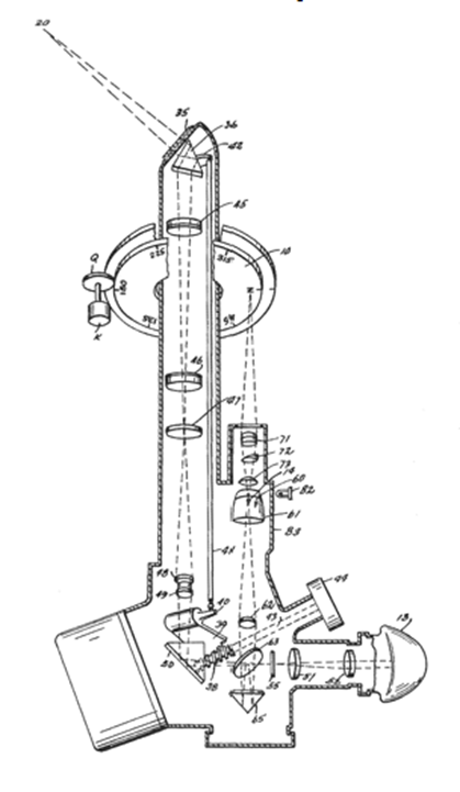
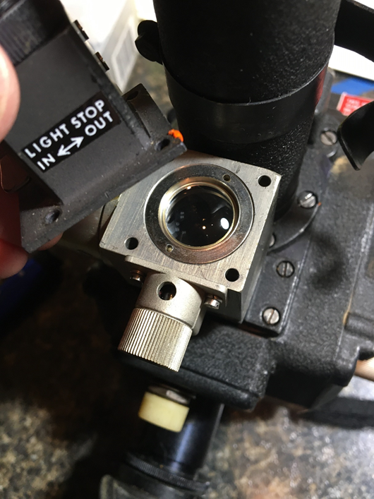
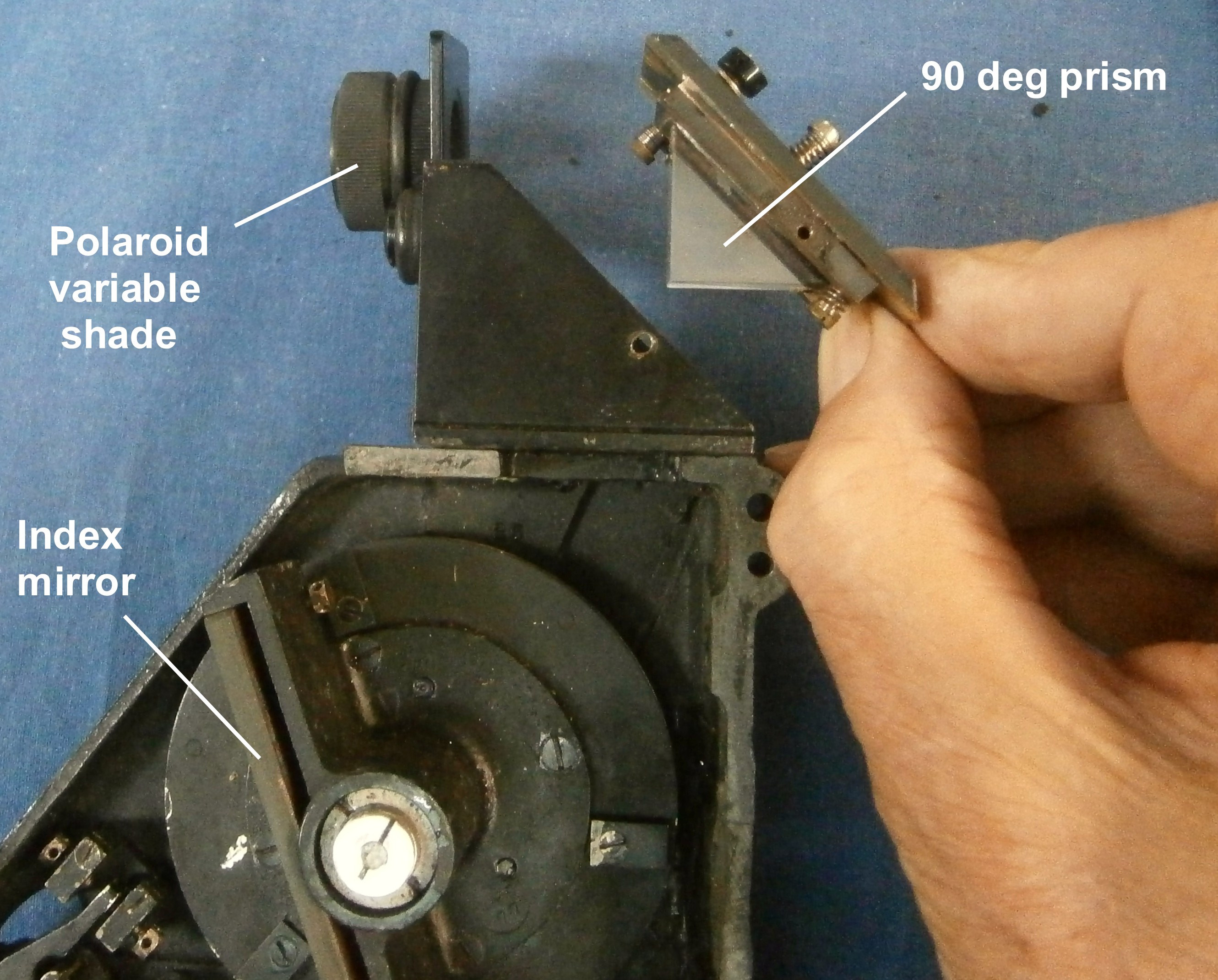
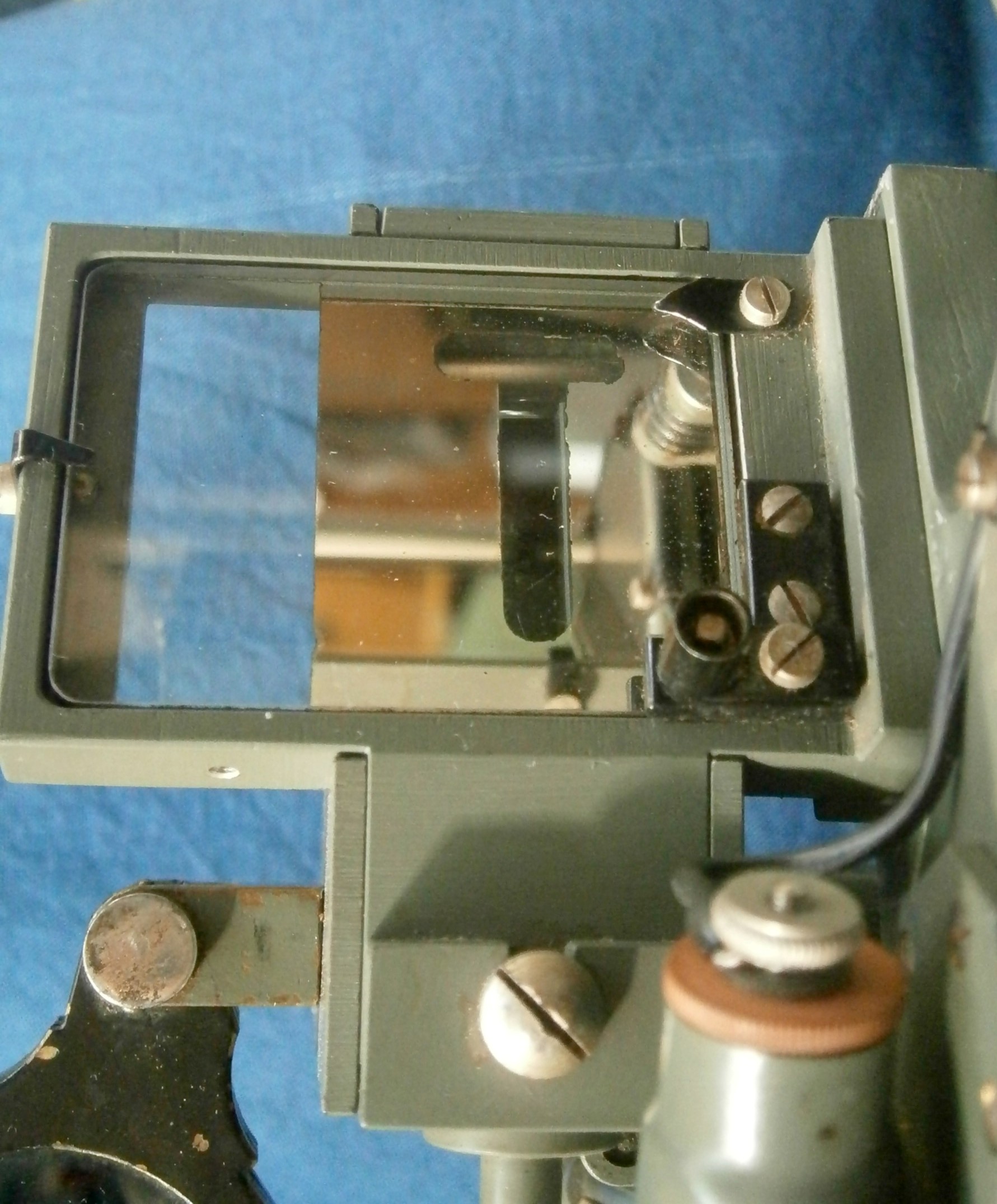
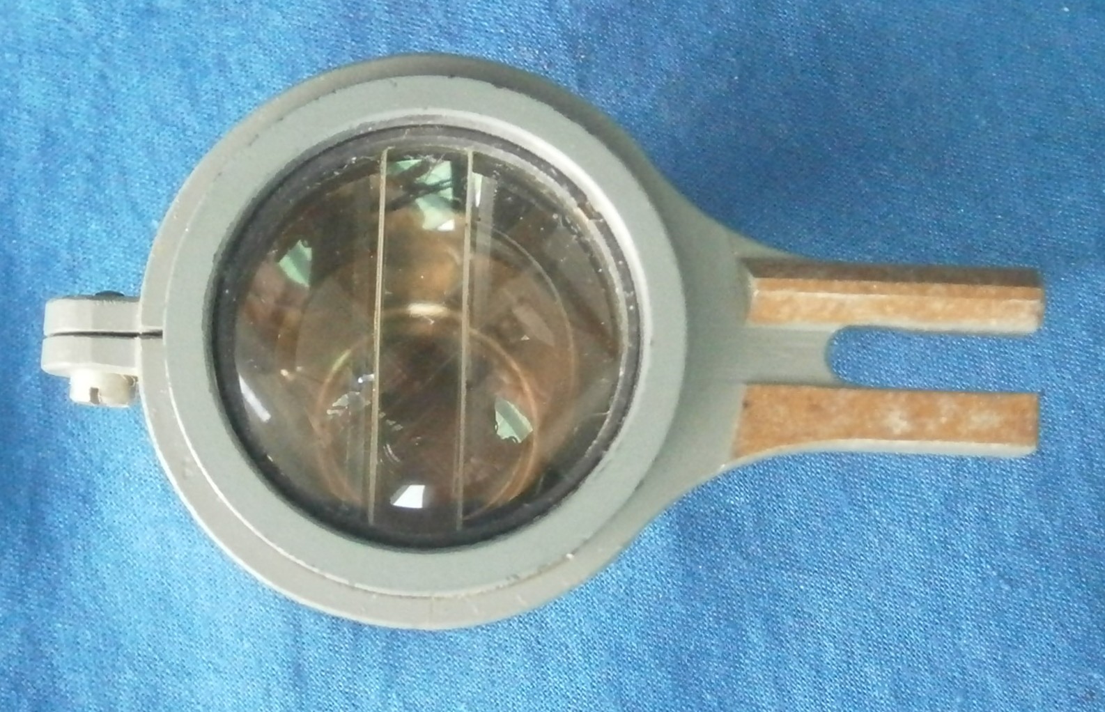
If no bubble is visible in the eyepiece, there is another simple method of checking if there is a bubble.  There is a lens housing attached to the top of the bubble chamber which is used to provide a means for the navigator to a view a rotatable azimuth ring attached to the sextant mount (this provides the navigator with the means of swinging the sextant to the precomputed bearing of the object to be sighted).  A more reliable method to determine if there is fluid in the chamber is to simply unscrew this lens and then set the lever on the side of the lens housing to “Diffuser Out” which then exposes the top of the bubble chamber.  If you move the instrument around, you can then look for fluid in the chamber.  Shining a light into the eyepiece, while you look down into the lens housing, may help.

Figure 2: Gray bubble chamber between the black lens housing and the instrument chassis.  Unscrew the lens at the top of the housing then move the lever (out of sight on the left side of the lens housing) to “Diffuser Out” to reveal the top of the bubble chamber (also see Figure 5).

If you can see fluid or a bubble looking down into the lens housing but not looking into the eyepiece, then the bubble chamber is likely ok but the pellicle needs to be replaced.

If you don’t see a bubble or any fluid sloshing around when looking into the lens housing, then you likely will need to fill the bubble chamber.  While the repair manual for the Kollsman instrument does seem to imply that a set of fixtures with valves, reservoirs, and temperature control are required, it’s actually a simple procedure to do on a typical hobby bench.

Tools and supplies and such

To access the fill port, you will need to remove the bubble chamber from the instrument body – a good set of flat bladed screwdrivers is a good place to start but I found that a larger “precision” flat bladed screwdriver did the trick.  The latter is useful given some of the tight spaces in which you are working.

Figure 3: I have a set of very nice flat bladed screwdrivers, but the two rear screws on the lens housing are so close to the periscope tube and the screwdriver handle is so fat that I cannot use it.  This particular screwdriver worked, fine, however, as the screws are not snugged down with a lot of torque.

A modest sized syringe is very helpful – a large bore needle is sufficient and need not be sharp.  The bubble chamber is quite small so 10ml capacity is a good place to start.

Having a means of not losing the very small screws you’re about to remove is a good idea. Easiest is to clip an apron to the underside of the table at which you are working. I use bits of Velcro stuck to the underside of my various benches.

A Viton sheet or O-rings to form the seal on the filler port.  I had good success with both o-rings and discs, but the manual does specify a disc rather than an o-ring.  I used a simple hollow punch to make discs from the Viton sheet to fit the recess for the filling port. 

Amazon.com: U-Turn Fasteners – Type A Black Viton Rubber Sheet 1/16 Thick – 6 x 6 inch (FKM) Fluorelastomer Gasket Material (2 Sheets) : Industrial & Scientific

Note that something as resistant to attack as Viton is not strictly necessary if using the correct fluid (see immediately below), but it does not hurt to use it.

A few ounces of 0.65 centistroke (CST) silicone fluid.  Silicon fluid is non-toxic and non-flammable – I am told that it is used in common things like skin care products.  This is in contrast to other clear fluids used in earlier bubble chambers that can be toxic if inhaled in large quantities.  However, the very low viscosity silicone fluid does rapidly evaporate so I did this work in a very well ventilated area.

Silicon fluid also does not degrade seals unlike other fluids.

However, silicone fluid can be hard to find.  A friend with far more patience than I was able to find a good source from Midwest Lubricants: Silicone Fluids (midwestlubricants.com)

Be careful to order the correct viscosity fluid – 0.65 centistroke is less viscous than water and is specified in the Kollsman repair manual.  Using a more viscous fluid likely will cause issues ranging from gumming up the bellows to having a bubble that isn’t “lively” which would give erroneous and random results.

Filling the chamber

Put the instrument on a padded cloth of some sort to prevent any inadvertent bumps to the instrument and to catch small bits from falling into the maw of the Carpet Monster if you are as ham-fisted as I am.

The filler port for the bubble chamber is on the rear facing side where the periscope tube interferes with access to the port.  The bubble chamber must be removed to access the filler port.

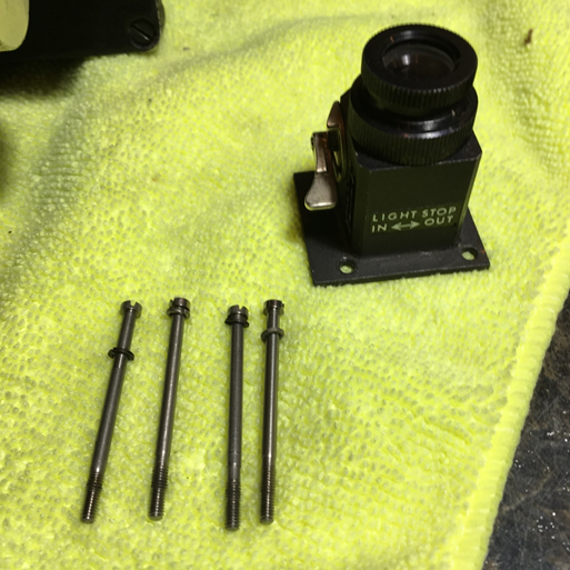
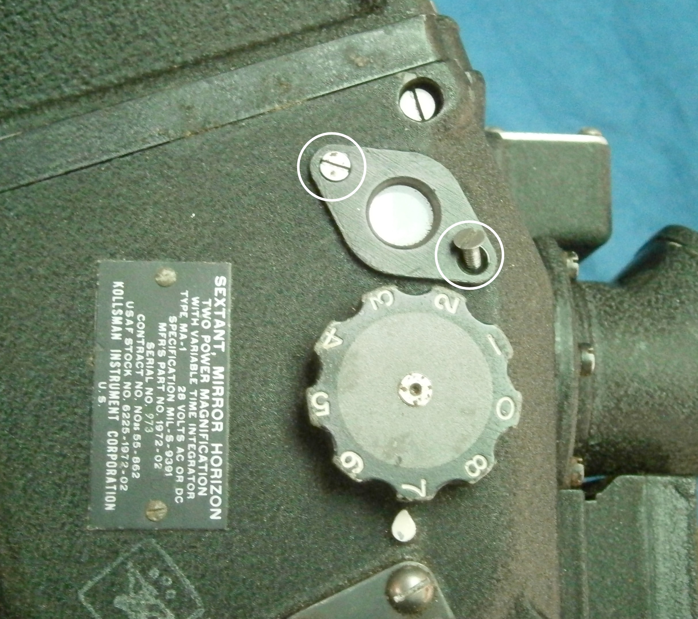
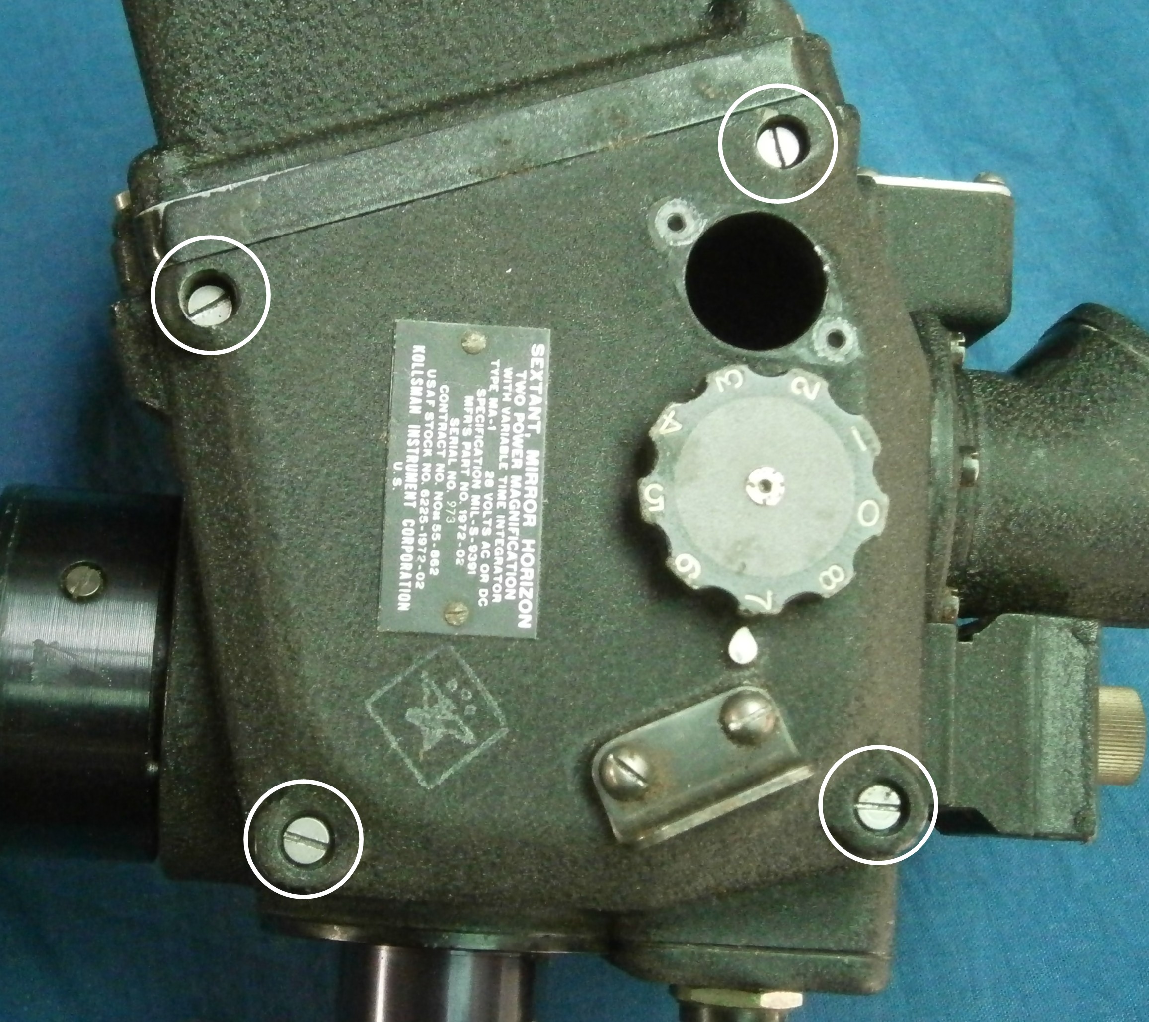
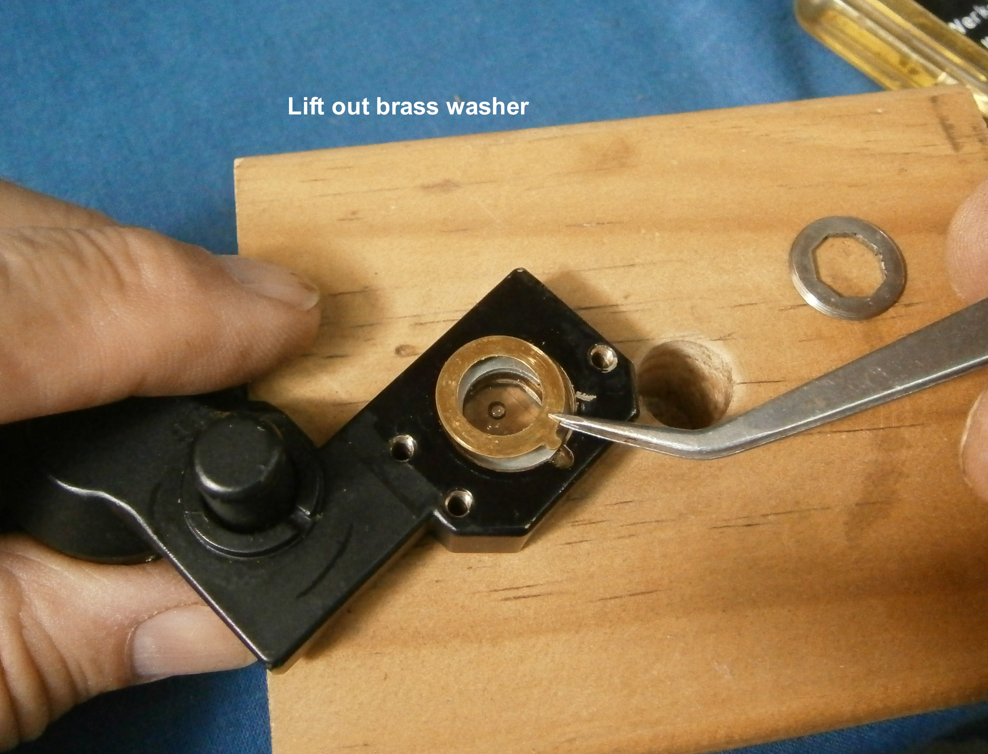
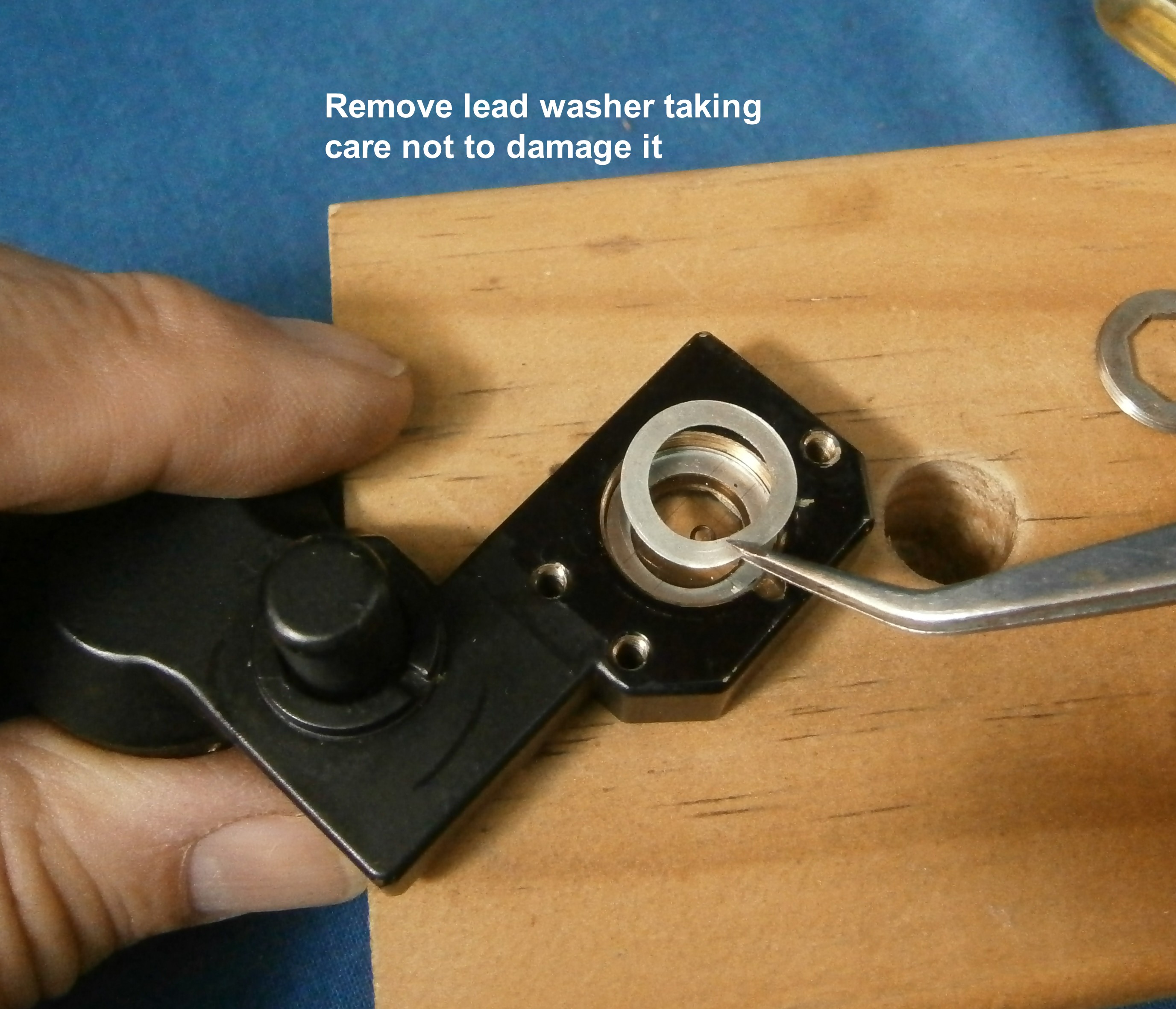
There are 4 screw heads around the base of the lens housing – these screws hold the lens housing to the bubble chamber and the bubble chamber to the instrument chassis.  These are relatively long screws but be careful not to lose the washers.

Figure 4: Removing the 4 long screws to remove the lens housing to the bubble chamber – these screws also hold the bubble chamber to the instrument chassis.  The large knob at lower left is the bubble size adjustment knob.  The knurled cap at center right houses a lightbulb to illuminate the bubble for nighttime sights.

A tight-fitting screwdriver blade to the screw’s slot is, of course, preferred.  Take care working with these screws.  Note that some instruments have screws that have been painted over – you will have to break the paint away from the screw slots to seat the screwdriver properly.  An eyeglass screwdriver did this with little fuss.

The lens housing simply comes off.  There is no gasket material on this side of the bubble chamber.

Figure 5: Remove the lens housing – top of bubble chamber exposed.
Figure 6: Long screws and washers.  It’s easy enough to not lose the screws but take care with the washers.

At this point, the only thing holding the bubble chamber to the chassis is the stickiness of a thin rubber gasket that seals the interior of the instrument from external air and moisture.  Depending on how long ago the chamber was put on, it can take a bit of motivation to free up the chamber.  After several moderately strenuous attempts to pull it off by hand, I used the end of an eyeglass screwdriver very carefully placed in between the chamber and the chassis and VERY LIGHTLY tapped it with a small ABS hammer and the chamber popped off with little fuss.  If you choose to use this method, BE VERY CAREFUL.

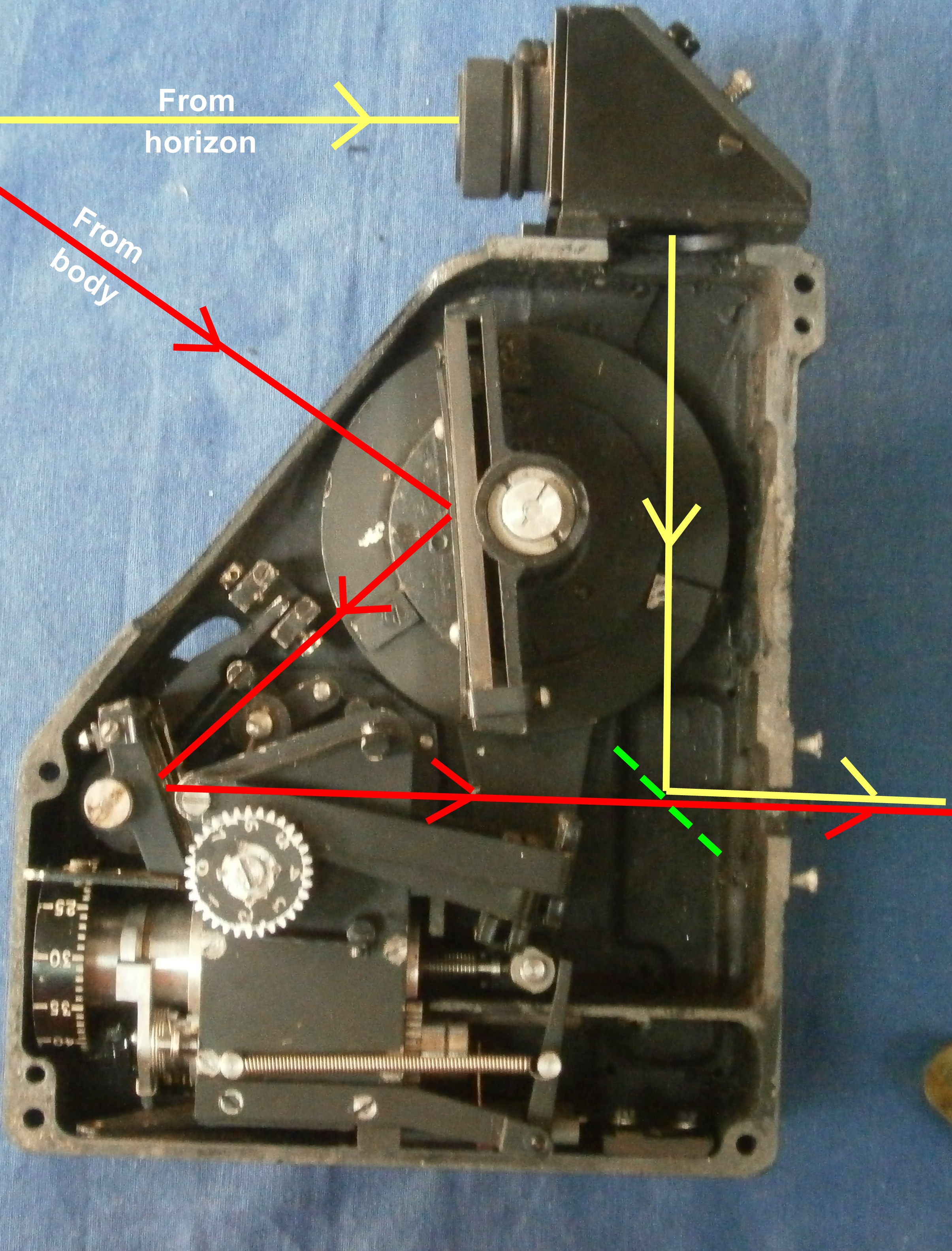
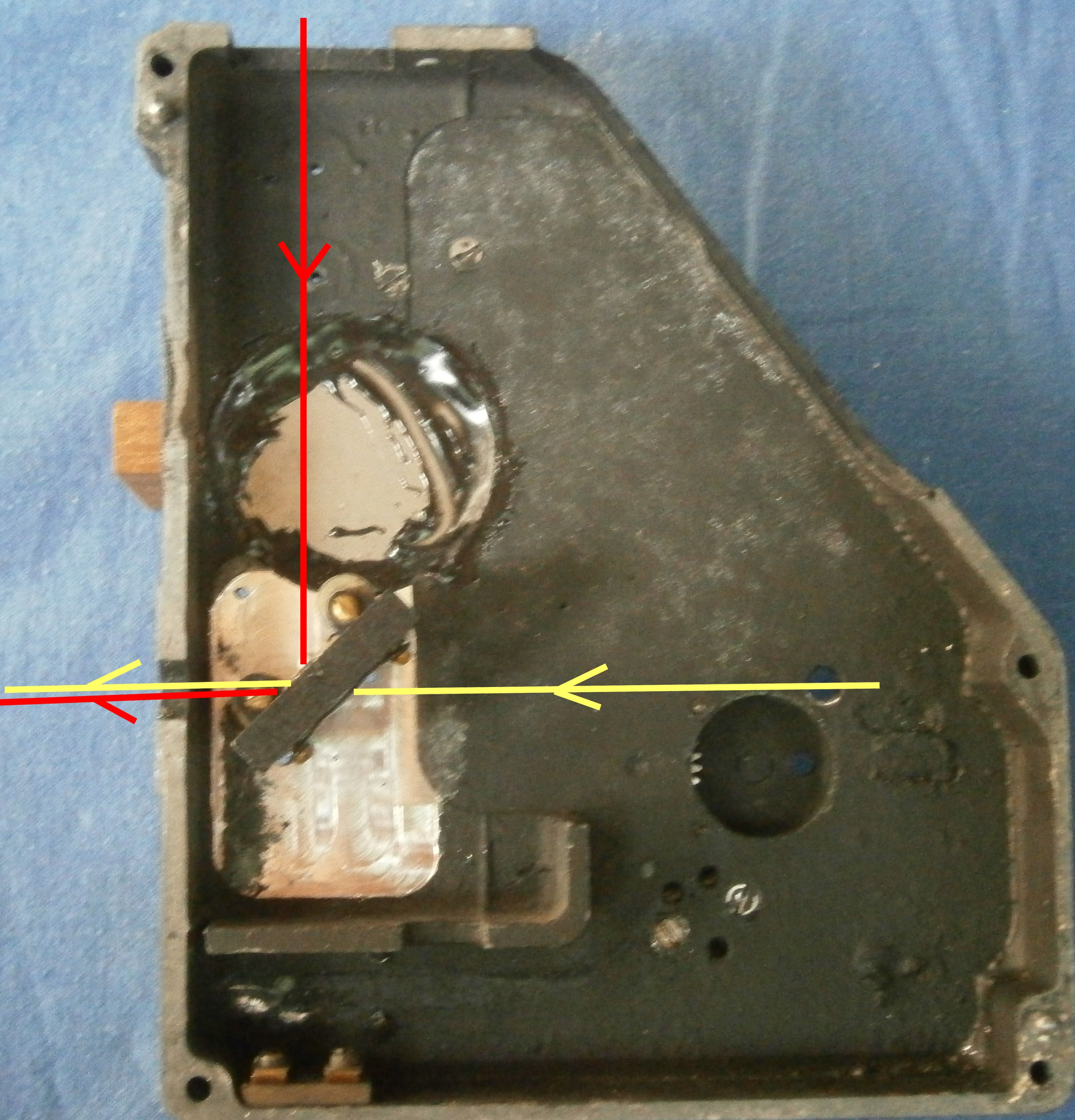
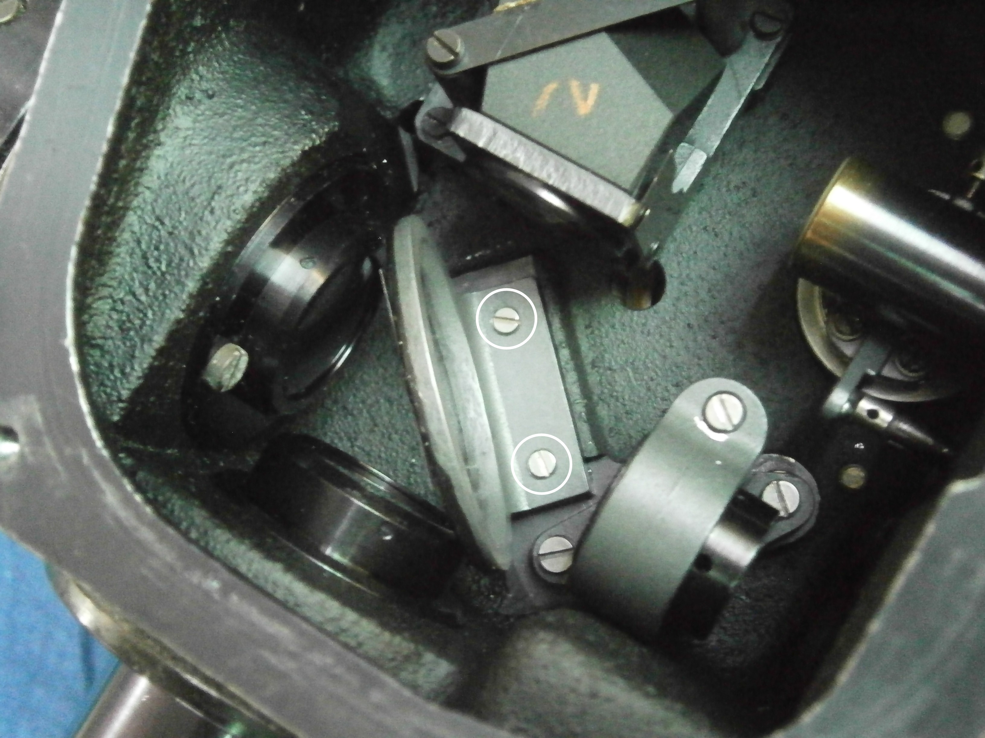
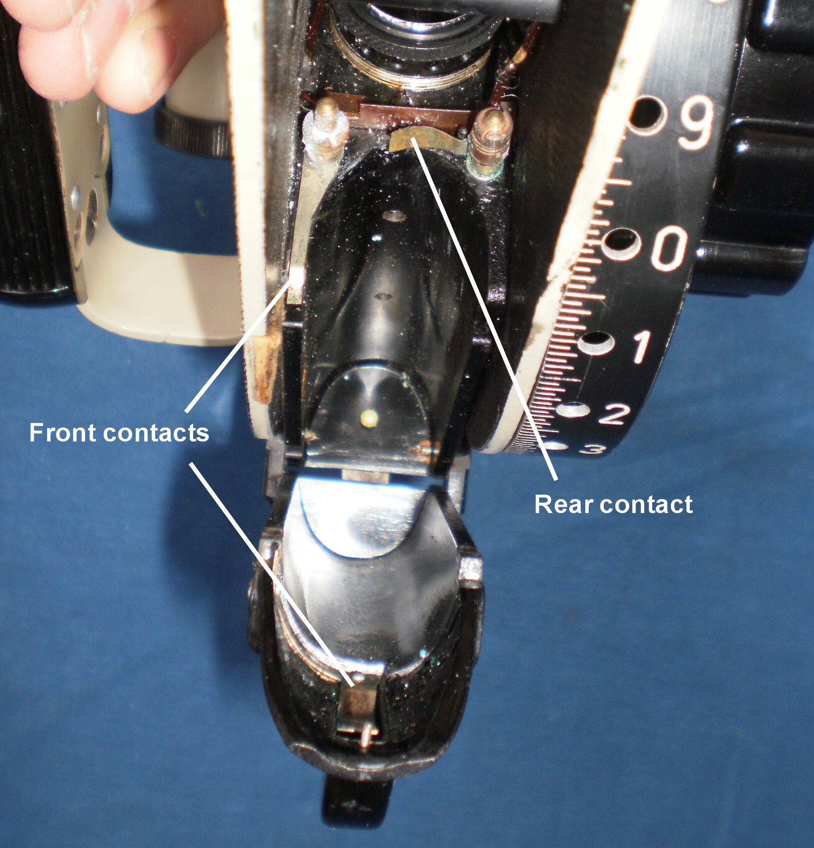
You don’t want to motivate the removal using percussive maintenance methods – looking at Figure 8, you will see that there is a small insulated tube that comes out of the chassis and fits into the bubble chamber.  This is a pretty important electrical connection as it feeds electrons to the bubble illumination so don’t bust it.

Carefully remove the chamber from the chassis being mindful to not tear the gasket as you pull the chamber away.

Figure 7: The bubble chamber freed from the instrument chassis with rubber gasket still (mostly) tenaciously sticking to it.  See notch in gasket in upper left corner provided to clear the electric contacts.

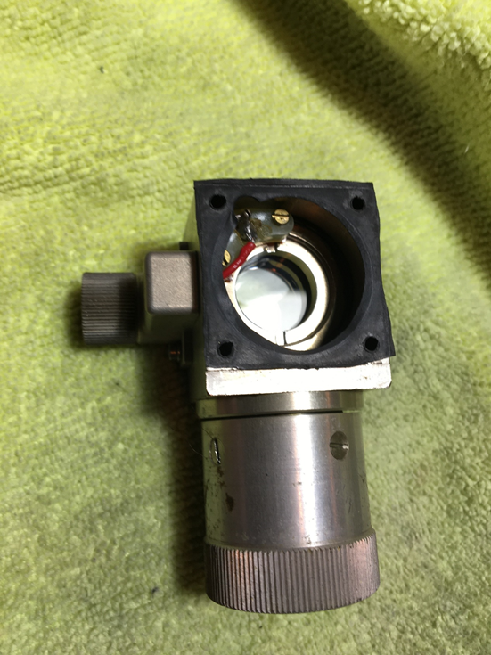
Carefully remove the gasket and set it aside.  Note that there is a notch in one of the corners of the gasket that lines up with the socket that brings electric power to the lamp attached to the chamber.  You will have to reinstall the gasket with the correct orientation when it comes time to put the chamber back onto the chassis.

I then used a bit of blue masking tape to cover the resulting hole in the instrument – this particular instrument has an intact pellicle so it felt better to cover the hole than to not.

Figure 8: Cover the instrument cavity to protect the pellicle.  Note socket for the electric connection on the lower right corner.

In the next image, we see the cover for the filling port.  This cover is up almost against the periscope tube when the chamber is on the chassis.

Figure 9: The filler port is under the cover held on with two screws.  I am not sure where the scratches and scuffs came from.

Here is the filling port exposed after removing the cover.

Figure 10: With the two very small screws removed, we see the filling port.  Note flattened condition of rubber o-ring.

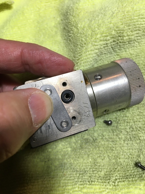
In this image we see that, at the previous servicing, an o-ring was used to seal the port.  The maintenance manual specifies a disc.  The o-ring, tho still pliable, was completely flattened.  This is where I suspect the chamber leaked.

Not knowing better, I originally used a Viton o-ring to replace it.  The dimensions of the o-ring I used was 2.90mm diameter x 1.78mm thickness and it worked fine for at least a month.  I eventually replaced it with a Viton disc made from a sheet 1/16” thickness Viton and a hollow punch.

A test fitting of the disc indicated that it was only slightly taller than the hollow around the filling port.  I punched a second one and then thinned it using fine sandpaper.  My plan was to stack them with the unsanded disc on the port and then the sanded disc on top of it to provide tension to seal the port under the cover.

Figure 11: A dry bubble chamber.

To fill, I used a syringe with a large bore needle, but injecting it directly into the port just resulted in silicone fluid flying about. 

Figure 12: I found this orientation the best for keeping fluid going in. The syringe is massively oversized – I used what I have, but you can certainly get by with a much smaller syringe.

The procedure takes a bit of time at this point.  I would add a bit of fluid to the port letting surface tension of the silicone fluid hold the fluid at the filler port.  I would then put the syringe down and rotate the bubble adjust knob so it sucks the fluid in – then I would rotate the knob in the opposite direction so fluid would start to come back out of the filler port, reverse the knob again a bit tiny bit, then add a bit more fluid.  Repeat many times.

Sadly, as I write this, I cannot recall if I rotated the knob towards the “Bubble Increase” or opposite direction.  You will quickly figure it out, however – if fluid comes out, turn it the other way!

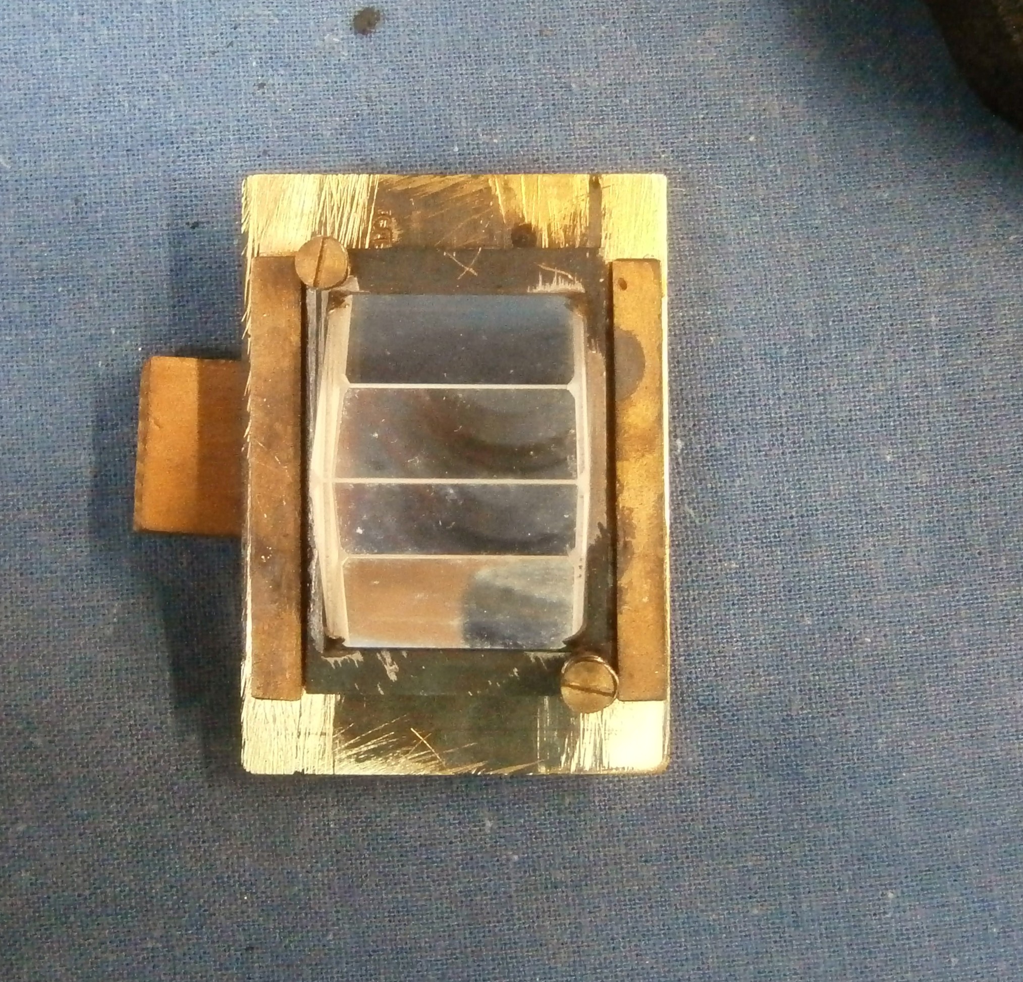
At some point, the bubble looked like this and I was not able to get any more fluid into it:

Figure 13: You can see your progress by looking into the bubble chamber.  The gasket is still on in this picture – but I recommend removing it during this process.  This is about as full as I could get it.

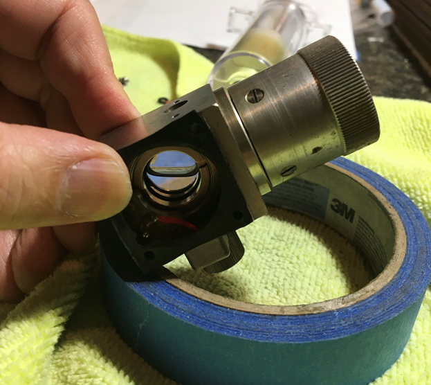
As shown, this is about as full as I was able to get it using the syringe and working the knob.  However, this does not indicate failure.

The bubble adjust knob has a bellows – what I did at this point is seal the fill port with the discs and then the cover plate and screws so I could see if I could form a smaller bubble.  To do this, follow this procedure:

  1. Hold the chamber level as though it was on the instrument (bubble adjustment knob to the left and light bulb housing pointing towards you)
  2. Turn the bubble adjustment knob so it reaches the stop at the “Increase Bubble” direction (full clockwise rotation until it reaches the stop)
  3. Tilt the chamber ~70⁰ to the left (so the knob is pointing down and left, light bulb housing still pointing towards you)
  4. Turn the knob slowly (or quickly – you may need to experiment) away from the stop (counterclockwise) until it hits the opposite stop.  If things are going well, you should see the bubble start to shrink.
  5. Repeat from step 1 as necessary.

In normal operation, this is how one shrinks the bubble.  By rotating the chamber with the bubble adjust knob pointing down and left, the bubble is up against a notch in the chamber which leads to the bellows assembly in the knob.  Moving the knob counterclockwise siphons gas into the bellows shrinking the bubble.  However, the bubble must be in the notch for the gas to be pulled into the bellows.

You may need to repeat the process several times – first level the chamber again, then move bubble adjust knob to the “Increase Bubble” stop, tilt, move the knob to the opposite stop.

After a few cycles of this, I got:

Figure 14: As seen from the top, a good bubble!

Doing the shrink bubble procedure a few times, I was able to shrink the bubble to nothing so that it looked just like Figure 11!  If you do this, do not fret – by redoing the procedure above but moving the knob towards “Increase bubble” instead of away, you can create a bubble.

It is a good idea to store the sextant with the bubble adjustment knob set back to the “Increase Bubble” stop – this is the preferred position when not actively using or adjusting the bubble.

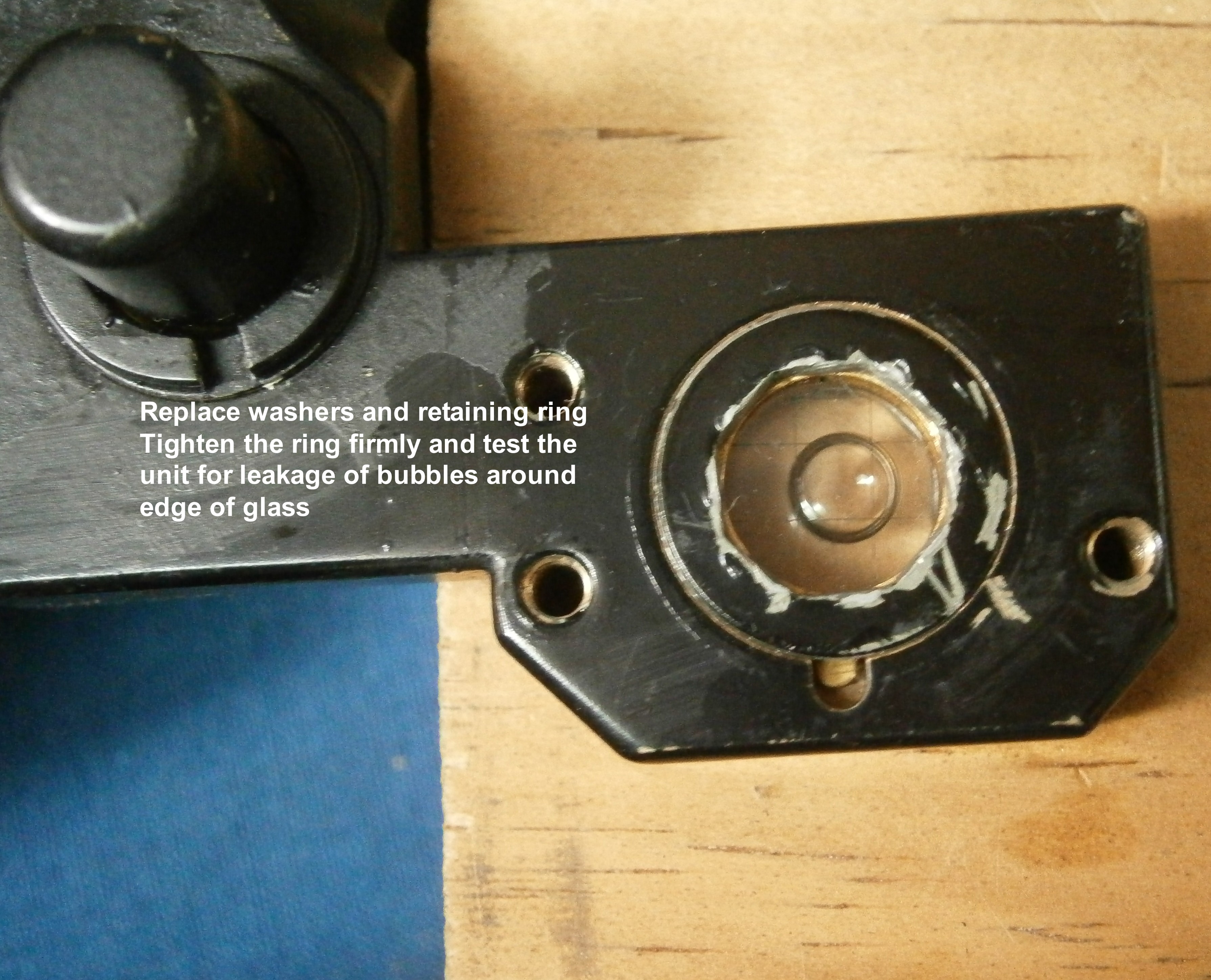
I rechecked that the plate on the filler port was snugged down with the Viton discs in place under it and, at this point, all that is left to do is re-assemble the bubble chamber and lens housing to the chassis.

Make sure to clean the top lens of the bubble chamber.

Getting the gasket back on is a little fussy.  First, make sure it has the correct orientation so that the notch in the gasket clears the electrical contact area.  What I eventually did was put the lens housing back onto the bubble chamber, then put the screws thru the two, then put the gasket onto the protruding screws.

Figure 15: Getting the gasket back on.  Hold the screws in place with tape.

Then it is a relatively simple matter to just align the screws to the holes on the chassis and carefully snug them down.

Closing remarks

Note that, as seen in Figures 13 and 14, there is still a fair amount of air still in the chamber’s bellows when I reached the point where I could not get more fluid into it.  I do not know if this can be reduced using a different procedure, so if anyone does know I would love to hear about it.  The method described above does work well enough to make a bubble allowing the sextant to be used.

Because I pulled the bubble chamber off and the gasket is non-uniform, I needed to re-establish the instrument’s index error.  Using a custom 3D printed mount on a tripod, this is a quick process – because of the stability on the tripod, the bubble can be held still which makes for very accurate results.

Figure 16: I have a friend who is very handy with 3D printers.

The bubble chamber I refilled still seems to have retained its bubble after 6 months – it allows me to shrink the bubble to do star shots and expand the bubble to do Sun shots and, quite agreeably, the bubble has not disappeared.

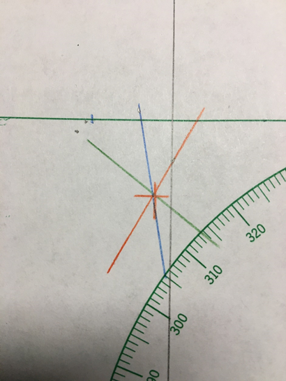
It may well be that I have seen only exceptional bubble chambers free from defects other than the filler port seal – this article only addresses the refilling of the chamber, not other repairs that may be necessary. These Kollsman sextants can be very accurate, even with the 50+ year old clockwork averagers.  Here is a representative 3-star fix taken with this repaired sextant and its attached clockwork averager:

Figure 17: Representative fix with this repaired Kollsman instrument.  Not bad for a clockwork that’s 50+ years old from my back yard in the middle of the woods.

And a fix that looks like this is not uncommon:

Figure 18: Not a bad fix at all.

These Kollsman periscopic sextants are robust and quite capable of taking very accurate fixes from places far from a sea horizon or in the full darkness of night.  It is a shame to see these instruments gathering dust especially for something, like a leaking filler port seal, that turns out to be relatively easy to fix.

Arthur Leung

North Carolina, USA


28 05 2021

LAND USE CONVERSION OF MARK IX BUBBLE SEXTANT

A few years ago, I bought a Mark IX bubble sextant for parts from a local auction web site. I had vaguely noted an excrescence had been added to the top, and when it arrived I found that it contained a ninety degree prism. The bubble unit had been removed and in its place was a half-silvered mirror angled at 45 degrees. Someone seemed to have attempted a conversion so that the sextant could be used at sea, using the natural horizon. This in itself is not a bad idea, as the Mark IX series of bubble sextants represents a cheap way of getting an instrument with a digital read out, as shown in Figure 1.

Figure 1: Right-hand side of sextant.

The index mirror is rotated in steps of 10 degrees(actually 5 degrees but the light ray is deflected through 10) by depressing the knob and rotating it, when on releasing it it clicks into the selected value. Pushing up the 5 degree knob adds five degrees rotation to the ray deflection. The fine adjustment knob adds up to 8 degrees fifty minutes to the value set by the 10 degree knob.

Upon further exploration of the excrescence at the top it turned out to contain a right angle prism to divert light entering it directly downwards into the instrument. A variable polaroid filter can be swung to filter the incoming light. I suspect the fitting was canabalised from something like a WWII drift meter. A half-silvered mirror with a silvered aperture of only 18 x 7.5 mm diverted the down-coming rays into the eye hole, joining the rays from the observed body, as in a normal sextant.

Figure 2 shows the interior of the sextant. The gearbox, as well as counting off the degrees and minutes, also rotates the index mirror. The shades control allows seven combinations of three shades of increasing total density

Figure 2: Interior mechanism.

Figure 3 shows the light path of the conversion. Horizon rays are shown yellow, body rays are shown red and the mirror as dashed green.

Figure 3: Light path

It is not my intention to provide detailed instructions on replicating this instrument layout, as much will depend on the skills and workshop resources of the reader. However, a few details may help.

Figure 4 shows the prism mounting from the side. The prism is cemented to a back plate which is held against three points by two springs. The three points are a fixed nipple and two screws for adjusting index and side error.

Figure 4: Side view of prism mounting.

Figure 5 shows that the prism backplate lies between two guide rails, soldered to a further plate which forms the rear of the mounting and which is threaded for the adjusting screws.

Figure 5: Apical view of prism mounting.

I felt that the view through the half-silvered mirror was rather restricted and also discovered that it was not well-centred on the light rays, so I replaced the mirror and its mounting with one carrying a 50% beam splitter measuring about 25 x 20 mm. This is mounted in the left half of the instrument frame, as shown in Figure 6 with the light path.. By carefully adjusting the permanent height of the mounting above the frame I was able to get the horizon view to occupy roughly half of the field of view, while the body rays occupy the whole field of view. The horizon f.o.v. is somewhat brighter, as it has passed through fewer air-glass interfaces.

Figure 6: Beam splitter position.

For those who are not familiar with the Mark IX series of bubble sextants, the two halves mate together, located by two dowel pins and four screws a shown in Figure 7. Those interested in restoring A Mark IX, IX A or IX BM to working order as a bubble sextant will find my restoration manual a useful guide. See: My Bubble Sextant Restoration Manuals for details.

Figure 7: The assembled instrument.


Replacing the Pellicle of an MA1 sextant

8 10 2016

This post is preceded by  “A Countinho-Pattern Bubble sextant’; “How to Refill C Plath Bubble Artificial Horizon”; “The SOLD KM2 Bubble Sextant”; “C Plath Bubble Horizon Attachment”;“A gummed up AN5851-1 averager”, “Bubble illumination of Mk V and AN 5851 bubble sextants” ,  ”Refilling Mark V/AN5851 bubble  chambers” ,  ”Overhaul of MkV/An5851 bubble chamber” ,  ”AN5851-1 : jammed shades carrousel” ,  ”A Byrd sextant restored” ,  ”Update on Byrd Aircraft Sextant”, “A nautical sextant bubble horizon” and “Sealing A10 vapour pressure bubble chambers.”

light-path

Figure 1: MA 1 light path diagram.

Figure 1 shows the light path diagram for the MA 1 aeronautical sextant click on it to enlarge). Its near relative, the MA 2 uses a spirit level as a horizontal reference, but the MA 1 uses a mirror whose surface is maintained horizontal by a hanging weight damped in fluid. Light from a bulb passes through a condenser lens system, through an orange-coloured reticle, through a thin transparent membrane or pellicle, through an objective lens and then is reflected off the mirror. On its return path it is reflected off the under surface of the pellicle into the eyepiece.

Rays from the observed object pass via the index prism and an objective lens system, are deflected through 90 degrees by a pentaprism and then pass via another reticle into the eye piece in such a way that the black lines of the object reticle, the orange lines of the mirror reticle and the observed object may be in view together. The object is kept in coincidence with the orange reticle, as far as possible in the centre of the field of view, as indicated by the object reticle.

The pellicle was probably made from flexible collodion, a substance based on nitro-cellulose that forms an exceedingly thin film, but which suffers from the disadvantage of being very delicate and prone to distortion and wrinkling if it becomes damp. Forty-odd years after manufacture, the dry nitrogen with which the instrument was filled has often been replaced by air and the dessicator has become saturated with water, so that the image of the orange reticle becomes distorted by wrinkles. While very thin transparent plastic films are now available in the form of food wrap, it seems to me to be much simpler to replace the pellicle by a microscope cover slip. Its thickness is about 0.14 mm and so light is reflected off both surfaces of the glass to give a double image of the horizontal reticle line. This is not necessarily a disadvantage, as it is easier to place an image of a star between lines than it is to superimpose the image upon a single line, though motion of the aircraft is likely to make this a moot point.

There is a method using food wrap and I include it as an appendix.

The first step is to remove the dessicator by withdrawing two countersunk screws circled in white in Figure 2. This makes it slightly easier to remove the left side of the instrument together with the shades mechanism and also allows the dessicant to be refreshed if the granules are pink or white. The end of the dessicator unscrews and the granules can then be tipped out onto a shallow tray and baked in an oven at 120  Celsius for 20 minutes or until they have regained a blue colour.

pellicle-renewal-001

Figure 2: Remove dessicator.

Then the four corner screws are removed as shown in Figure 3. Remove the screws completely before attempting to lift off the side cover. Then lift the rear of the cover a few millimetres and slide the cover backwards for a few millimetres, to avoid fouling the shades mechanism on the frame.

pellicle-renewal-002

Figure 3: Remove left cover.

This exposes the pellicle on its frame. Removal of two screws allows it to be lifted out for inspection, holding it by its edges (Figure 4).

pellicle-renewal-003

Figure 4: Remove pellicle frame.

If the pellicle appears to be flat and undamaged, dust particles may be removed by gently blowing dry air on to it or by very light brushing  with a soft camel hair brush. If you are ham-handed it is better to leave dust in place rather than risk damage to an intact pellicle. If, however, the pellicle is broken or wrinkled, remove its remains with a finger nail and then clean the front machined surface with ether solvent. It is then a simple matter to place three tiny drops of super glue on the frame and, using tweezers, to glue a microscope cover slip in place (Figure 5). A nicely worded request for a small handful of cover slips is unlikely to be refused at your local medical laboratory. They are perfectly clean as they come from the maker, so try to keep them that way.

pellicle-renewal-004

Figure 5: Replace pellicle with cover slip.

Figure 6 shows the eyepiece view after replacing the pellicle with a cover slip.

pellicle-renewal-006

Figure 6: View through eyepiece, using cover slip as semi-reflective mirror.

APPENDIX

Using food film as a pellicle replacement is slightly more difficult:

1)  Obtain a circular embroidery frame such as may be had for a very few dollars and stretch a piece of food film (Clingwrap, Gladwrap etc) over it, adjusting the frame until the film is perfectly flat and wrinkle free. Make sure that it is perfectly clean and free from finger marks.

2) After cleaning old pellicle off the frame, place a smear of two-part epoxy adhesive (e.g. Araldite) around the frame, just outside the flat machined area, avoiding placing adhesive on the flat surface itself.

3) Set the frame down on the centre of the film, adding a weight of a few hundred grams to hold it in place until the adhesive dries. Then trim off excess film with sharp nail scissors or the like.


A Coutinho-Pattern Bubble Sextant

6 05 2016

This post is preceded by  “How to Refill C Plath Bubble Artificial Horizon”; “The SOLD KM2 Bubble Sextant”; “C Plath Bubble Horizon Attachment”;“A gummed up AN5851-1 averager”, “Bubble illumination of Mk V and AN 5851 bubble sextants” ,  ”Refilling Mark V/AN5851 bubble  chambers” ,  ”Overhaul of MkV/An5851 bubble chamber” ,  ”AN5851-1 : jammed shades carrousel” ,  ”A Byrd sextant restored” ,  ”Update on Byrd Aircraft Sextant”, “A nautical sextant bubble horizon” and “Sealing A10 vapour pressure bubble chambers.”

All Figures may be enlarged by clicking on them. Return to the post by using the back arrow at top left.

Brief history

In 1922, Gago Coutinho, a Portugese naval aviator and inventor, was the first to fly the Atlantic, from Lisbon to Rio de Janeiro via the Las Palmas and Fernando Norohna using celestial navigation. According to A J Hughes, he descended to low levels to use the natural horizon and it is not clear whether he used an artificial horizon instrument of his own design, adapted from one by C Plath, but at any rate, he took such an instrument with him. As Figure 1 shows, this historic instrument was a vernier sextant fitted with an artificial horizon in the form of a longitudinal level vial and with scale illumination

Early sextant

Figure 1: Admiral Coutinho using his early bubble sextant.

With the cooperation of C Plath, the sextant was further developed at the request of the Portugeuse Navy and by 1927  had reached the final form which is often illustrated in histories of air navigation. Captain Wittenman navigated the Graf Zeppelin around the world in 1929 using such a sextant.The sextant was shown at the 1930 Berlin Airshow and was apparently popular with airlines in the 1930s.  It is said that  Henry Hughes and Son were also asked to develop the design but showed little interest. Their gifted chief designer, P F Everitt was developing Hughes’s own sextant, which evolved into the versatile Mark IX bubble sextant series. During the Second World War, the Japanese navy used a version of the fully developed sextant. Whether it was simply an exact copy of the Plath version by Tamaya, with better developed scale lighting, or whether it was in fact a Plath instrument with Japanese markings will probably never be known, but the Japanese certainly had a highly developed engineering and instrument industry, as many Western engineering firms and  instrument makers learned to their cost after the war.

General

A little while ago, I acquired such a copy, shown in its case in Figure 2 and, with its accessories, out of the case in Figure 3. It appears to be the fifth in a group of five and has naval markings.

2 In case

Figure 2: Coutinho pattern sextant in its case.

3 GA labelled

Figure 3: Contents of case.

The sextant differs from C Plath’s standard ladder pattern micrometer sextant in several aspects. The most obvious is the artificial horizon, and to accommodate this and also allow its use with the natural horizon, the index mirror is unusually tall (see Figure 8). The frame is of aluminium alloy, something that Tamaya in particular developed post-war when combined with a bronze rack, and the scale reads from – 15 degrees to 105 degrees. There was obviously no need for the scale to read beyond 90 degrees and it is possible that the unusually wide negative range of -15 degrees was intended to be used to determine the distance off known objects from the air, provided that the height of the aircraft was known. The design of the artificial horizon requires a special telescope in addition to a standard telescope; and two peep sights are also provided. Tamaya was probably the first to use a perspex light guide to illuminate the main scales and provision also had to be made to light the artificial horizon.

The artificial horizon system

Figure 4 shows the horizon mirror. Rays from the over-size index mirror are reflected off the silvered portion into the eye via a telescope or peep sight, while the natural horizon may be viewed in the usual way through the clear portion, using shades if necessary. When using the artificial horizon, the shades are all folded over to obscure the clear glass.

Horizon mirror face

Figure 4: Face of horizon mirror.

In use, the longitudinal spirit level is viewed through the upright of the T-shaped gap in the silvering by reflection off a mirror and the tilt level vial is viewed directly via the cross piece of the gap to ensure that the frame of the sextant is vertical (Figure 5).

5 Inside AH

Figure 5: General arrangement of interior of artificial horizon.

The longitudinal vial is illuminated from below through a slot in the casing, using a white diffuse reflector by day and a bulb let into the frame by night. The tilt level  seems to have been left to take its chances, as it is a little hard to discern by day and more so by night.The purpose of the blank shade whose axis is seen directly above the reflector is unclear. It was probably intended to reduce stray light at night from the bulb.

Figure 6 shows the tilt or cross vial in more detail.. It also shows the counter spring for the index error adjustment which must necessarily be made from the front of the mirror rather  than, more usually, the back.

6 b

Figure 6: Detail of cross vial.

7 AH from below

Figure 7: Artificial horizon from below.

A spare cross vial and two longitudinal vials in their carriers were provided and this enabled me to check an essential requirement of a bubble sextant: that once the bubble and the image of the observed body are brought into coincidence, they move together when the sextant is tilted fore and aft. For this to happen in most bubble sextants, the bubble is at the focus of a collimating lens, so that an image of the bubble appears at infinity when combined with a view of the object in a beam splitter. The  radius of curvature of the vial must be the same as the focal length of the collimating lens. In the Coutinho sextant, that translates into saying that the working distance of the lens that sees the bubble and the radius of the vial must be the same.

9 Spare vials 2

Figure 8: Kit of spare vials.

In 2001, when I was investigating how to grind sensitive spirit level vials, I made a version of the National Physical Laboratory small angle generator (described in On the Level. Model Engineers’ Workshop, October 2001). With it, I measured the sensitivity of a vial and found that the bubble moved 5 mm for a change in angle of 0.024 radians (1.389 °). Thus the radius of the interior of the vial is 5/0.024 ≅ 208 mm, and this corresponds roughly with the distance between the objective lens and the vial via the mirror, given that it is not possible easily to determine where in the lens system to measure from (see below).

Figure 9 shows the unusually large index mirror with the horizon mirror reflected in it.It is about 45 mm square, so that the mirror is tall enough for the instrument to be used with both artificial and natural horizon. C Plath and Japanese sextants that followed their practice were using large mirrors and objective lenses at a time when British, French and American sextants lagged well behind. To make an extreme comparison, the war-time standard C Plath sextant had an index mirror 56 x 42 mm (2352 mm²), a horizon mirror 55 mm in diameter with a silvered area of 2375 mm² and a telescope objective diameter of 40 mm (1256 mm²), while the Mark II US navy sextant had an index mirror 40 mm square (1600 mm²), a rectangular horizon mirror with a silvered area of 325 mm² and a telescope objective of only 18 mm diameter (255 mm²).

10 Index mirror

Figure 9: Index and horizon mirrors.

Telescopes and sights

Three sighting devices were provided: a standard 3 x 30 mm Galilean or star telescope with an extra long rising piece to bring it in range of the clear part of the horizon mirror; a 2 x 34 mm telescope for use with the artificial horizon (AH) ; and a peep sight with interchangeable sights, one a simple 1 mm vertical slit and the other a 1 mm slit expanding to a round 4 mm hole at one end, for use with the artificial horizon. I will describe only the two latter.

Figure 10 shows the general arrangement of the AH telescope.The body is a heavy brass turning held in a stout brass rising piece. Focusing is done by rotating  a knurled ring with a threaded peg which engages in a spiral slot cut into the wall of the eyepiece tube. The 12 mm diameter negative eye lens has a power of -21.25 dioptres or 47 mm, so we may take the focal length of the main objective lens to be about +95 mm (10.5D).

Scope sife view 001

Figure 10: Telescope for use with artificial horizon.

The objective lens  is combined with an auxiliary lens, selected so that when an object at infinity is viewed, the longitudinal bubble of the level is also in focus (Figure 11). As the combination has a focal length of about +70 mm (14D), we may deduce that the focal length of the auxiliary lens is about +280 mm (3.6D).

11 Objective

Figure 11 : Bubble sextant objective lens.

Figure 12 shows the objective lens exploded. A slice of auxiliary lens is cemented to a plane parallel glass and its convex side faces the convex side of the main objective lens, separated by a spacer ring. The whole combination is held in the body with a threaded retaining ring. At about the same time as this type of bubble sextant was conceived, Richard E Byrd, then a Lieutenant Commander in the US Navy, had constructed for him a sextant on the same principle, in which an auxiliary half lens allowed a single longitudinal vial to be viewed. There was no tilt vial. See my posts for 30 May, 2009 and 11 August 2009 for details of this sextant.

12 Objective exploded

Figure 12 : Objective lens dissected.

When the objective lens of a Galilean telescope is, say, half covered, that half of the image disappears, whereas with a Keplerian telescope, the whole image remains but is of half the intensity. Thus, with this special telescope it is difficult to superimpose the image of the observed object upon the bubble (since the auxiliary lens places it well out of focus); it can however be placed alongside. By careful choice of the index shades and by moving the eye to one side of the field of view, it is possible to superimpose the images, presumably utilising reflection off the front face of the unsilvered “T”, but I cannot imagine that this would be easy in an aircraft A corollary of this is that the bubble of the tilt level is not quite in focus, being nearer to the objective that the other bubble. It is also poorly lit and on the extreme outside of the field of view, even out of view altogether for spectacle-wearers. I imagine that it would need considerable practice to get the two levels and the image of the observed body in the right places together. On land, I can achieve only fleeting coincidences with the sun. I will report later on star observations.

Withe the peep sights (Figure 13) matters are easier, as the slot increases the depth of field and everything is more or less in focus, while the image of the sun and the bubble are about the same size. The two apertures are not, I surmise, intended to be used together, since only a view of the vial would be obtained. Rather, they are interchangeable and orientation is assured by a pin engaging in a vee-shaped slot.

13 Peep sights side

Figure 13: Peep sights in holder.

There seems little point to having the aperture with the round hole (Figure 14) since  a perfectly adequate view of the cross vial is had without it.

15 a Combined peep

Figure 14: Peep sight apertures.

Lighting system

Tamaya was probably the first to use a perspex light guide to carry light from a bulb to the scales of a sextant (Figure 15). The substantial black plastic handle contains a 1.5 volt “C”cell that provides current via a simple push button switch to the bulb (Figure 16). Earth return is via the body of the sextant and a special potentiometer in the bottom of the handle.

16 Scale lighting

Figure 15: Scale lighting.

Figure 16 shows the interior of the battery handle and some of the wiring. Note that the switch controls lighting to both the scales and the level unit. though both are not illuminated at once. Instead, the special potentiometer controls the intensity of the light to each in turn.

Lighting system 001

Figure 16: Battery handle.

At the front or left-hand end of the limb is a hole to accept the holder for the bulb that lights the level unit. The blank shade, the knob for which is visible at bottom left of Figure 16 is rotated upwards to prevent stray light from shining upwards and light from the lamp can then reach the white reflector and be diverted into the unit. In fact, relatively little light finds its way inside and in full darkness it is rather hard to make out the cross level bubble.

Lighting system 002

Figure 17: Level lighting.

The exterior of the potentiometer is shown in Figure 18, together with the socket for external power and Figure 19 shows the internal construction of the device.

19 Pot exterior

Figure 18: Potentiometer knob and power socket.

There are two separate resistance windings with a wiper inside the knob being common to both and the knob carries current from the battery via the central screw and metal cap. Each bulb may be switched on and its intensity controlled in turn, but not together, and the battery handle switch must be depressed for either to light.

18 Pot

Figure 19: Interior of potentiometer.


According to Freidrich Jerchow’s history of C Plath, From Sextant to Satellite Navigation, the sextant enjoyed some popularity in its fully developed form in the 1930s at a time when airships were seen as the long-distance aircraft of the future. It was probably quite suited for use in airships, which are notably stable and little subject to the effects of air turbulence, but as airships fell into disuse, so the sextant was overtaken by the development of other bubble sextants, all of which had circular levels and all of which directed an image of the bubble, apparently at infinity, into the light path via beam splitters. The particular sextant which I have described, however, has a placard indicating that it was made, or at least, sold,  in the ninth month of the nineteenth year of the Showa dynasty (Figure 20)  or September 1944, by Tamaya. The stamps each side of the serial number are naval marks. Compared to copies of the A8-A bubble sextant, which were also made in Japan, this would have been an obsolescent instrument and much more difficult to use in a fixed wing aircraft.

2962 008

Figure 20: Maker’s placard.

For completeness, I show the outside of the case in Figure 21. The furniture is brass with a heavy canvas handle in good condition. The interesting slanting comb corner joints seem to combine the advantages of dovetails with the large glued area of ordinary comb corner joints. Both top and bottom are attached with brass screws and the catch is supplemented by hook latches. I am unable to identify the wood.

1 Case exterior

Figure 21: Exterior of case.

I hope you have enjoyed reading about this rare and unusual sextant. You may also enjoy reading my books The Nautical Sextant and The Mariner’s Chronometer.


How to refill C Plath bubble artificial horizon

13 09 2014

This post is preceded by  “The SOLD KM2 Bubble Sextant”; “C Plath Bubble Horizon Attachment”;“A gummed up AN5851-1 averager”, “Bubble illumination of Mk V and AN 5851 bubble sextants” ,  ”Refilling Mark V/AN5851 bubble  chambers” ,  ”Overhaul of MkV/An5851 bubble chamber” ,  ”AN5851-1 : jammed shades carrousel” ,  ”A Byrd sextant restored” ,  ”Update on Byrd Aircraft Sextant”, “A nautical sextant bubble horizon” and “Sealing A10 vapour pressure bubble chambers.”

A friend recently asked me to refill the bubble unit of his C Plath artificial horizon. Someone had been there before me and mutilated the retaining ring for the top glass and left a leaky bubble chamber, but there was enough ring surviving for me to be able make a repair. Her’s how I did it in (mainly) pictures. Read this in conjunction with the post of 26 June 2012.

Figure 1: remove plate.

Figure 1: remove plate.

Figure 2: Remove lamp holder.

Figure 2: Remove bulb carrier.

Figure 3:

Figure 3:Displace bulb mount.

Figure 4: Remove bubble unit.

Figure 4: Remove bubble unit.

Figure 5: Remove top retaining ring.

Figure 5: Remove top retaining ring.

To remove the ring you will need to make a little tool from a piece of 10 mm square steel. File the corners off to make a symmetrical octagonal shape until it fits in the octagonal hole in the ring. You don’t have to fit a tommy bar. You could use a 10 mm AF wrench instead.

Figure 6: Remove washer.

Figure 6: Remove washer.

Figure 7: Remove another washer, carefully.

Figure 7: Remove another washer, carefully.

Figure 8: Prise out glass, even more carefully.

Figure 8: Prise out glass, even more carefully.

Figure 9: Rinse and add fluid as necessary.

Figure 9: Rinse and add fluid as necessary.

You can use absolute alcohol if you can get it, gin or vodka. I prefer to use iso-propyl alcohol (isopropanol) because the de-natured ethanol I can get is coloured purple. In an ordinary level tube I bleach it with a drop of household bleach, but am uncertain about its long-term effects in a metal and glass chamber. When you cannot draw any more fluid in, over-fill the chamber and add the glass, remembering to put it with the the concave recess down. A syringe with a 23 or 25 gauge needle is handy for adding the fluid.

Figure 10: Form bubble.

Figure 10: Form bubble.

If a bubble isn’t trapped under the glass, left one edge to let in a little air, about this much:

This should be as big as it gets.

This should be as big as it gets.

Replacing the bubble unit is the reverse of removing it.


The SOLD KM2 Bubble Sextant

4 11 2013

This post is preceded by  “C Plath Bubble Horizon Attachment”;“A gummed up AN5851-1 averager”, “Bubble illumination of Mk V and AN 5851 bubble sextants” ,  ”Refilling Mark V/AN5851 bubble  chambers” ,  ”Overhaul of MkV/An5851 bubble chamber” ,  ”AN5851-1 : jammed shades carrousel” ,  ”A Byrd sextant restored” ,  ”Update on Byrd Aircraft Sextant”, “A nautical sextant bubble horizon” and “Sealing A10 vapour pressure bubble chambers.”

In 1939, the SOLD-Libellen-oktant (SOLD level-octant), made by C Plath, went into service with the Luftwaffe (German Air Force). I have not been able to discover where the “SOLD” came from, but it is a fair bet that it is an acronym which includes the words “Sextant” and “Libelle” (Level). While it was used extensively by Luftwaffe reconnaissance aircraft especially, it is less well known that Naval  versions appeared,  with better protection from salt water spray and a self-contained power source in the form of a rechargeable NIFE battery.  The aircraft versions were powered via a flying lead. While the results of observations made with a bubble sextant at sea can be expected to be rather inaccurate, in some circumstances, on war patrol at night for example, or in poor weather when no horizon is visible, even a poor result can be better than none at all. Since this is a blog about the nautical sextant, it is with the nautical version that this post is concerned, specifically a KM2 (Kriegsmarine 2) of 1944. It differs otherwise only in minor details from the Luftwaffe version.

Please note that all illustrations may be enlarged by simply left- clicking on them. Return to the text by clicking on the back arrow.

Optical lay-out

Figure 1 shows the light path.  It is perhaps slightly easier to understand the path for night time observations of a star. The star is located by looking upwards through the partially reflecting mirror 5.  Light from the bulb 1 is reflected off mirrors 7 and 6, through a circular bubble level 2, off the reflective face of a pentaprism  3 into an objective lens 4, whose focal plane is at the bubble. The lens renders the rays parallel, so that the bubble then appears to be at infinity as it is observed reflected off the mirror 5. While keeping the star in view, the mirror 5 is  rotated to bring the image of the star and the image of the bubble together, when the angular altitude of the star above the horizontal may be read off a scale attached (indirectly) to the mirror 5. The radius of curvature of the bubble cell and the focal length of the objective lens are chosen to be the same, so that once the star and bubble images are coincident, they tend to move together when the sextant body is disturbed. For daytime observations of the sun, it is the bubble that is viewed through the mirror while the sun’s reflection off mirror 5 is observed indirectly. For this type of indirect observation, the mirror 7 is removed and a frosted window substituted, so that diffused daylight illuminates the bubble chamber, though daylight viewing with the bubble chamber illuminated by the lamp is possible too.

Figure 1: Light path.

Figure 1: Light path.

Averaging observations

Pitching and rolling of a ship imparts accelerations to the bubble chamber which for practical purposes may be considered as being random, and the bubble is seldom at rest. With early bubble sextants, a handful of observations were taken of the body and the altitudes and times averaged. However, random errors are reduced as the square root of the number of observations, so that, for example, to reduce the average error to a quarter, 16 observations have to be made and to reduce them to a fifth, 25 have to be made.

The next step was to provide some sort of drum on which marks could be made by the observer when he considered the bubble and body to be in coincidence, but it was soon pointed out that the bubble might well be considered to be at rest when it was in fact the subject of a large, but constant acceleration. The next step was to cause the marker to operate automatically at intervals of about a second, leaving the observer to maintain coincidence and to choose the median at the end of the observation period. A variety of clockwork averagers  giving a reading of the mean of the regular observations followed. The SOLD sextant, however, continuously  integrates rather than averages the observations. There is, however, probably very little practical difference in the results obtained by a British Mark IXA instrument, which averages 60 observations over 120 seconds and the SOLD which continuously integrates observation over a period of 40 to 200 seconds. The former is, however, more compact and of a better ergonomic design.

General arrangement

Figure 2: General arrangement, left side.

Figure 2: General arrangement, left side.

The optical parts, the battery and the integrator are sandwiched between two aluminium alloy plates joined together by pillars at intervals. Figure 2 shows the parts related to the outside of the left hand plate. At the front is a rectangular timing unit with its winding knob and starting lever. A shaft with a pinion on its end passes through the left hand plate to the integrator unit. A little below it and to the front is the daylight window which slides into a socket between the plates. This window can be withdrawn and a 45 degree mirror 7, Fig.1, substituted for night-time illumination of the bubble chamber. A slide allows a red filter to be placed in front of the bulb so that the bubble field appears to be red and night vision is preserved. The level unit control and air chamber lie outside the plat,e while the bubble chamber itself is held rigidly in the optical path between the plates. Provision is made to remove the level unit without having to dismantle the whole instrument. The left hand handle, behind the bubble control, has within it a rheostat to control the brightness of the bubble lighting, and below and to the rear of this can be seen part of the battery housing which lies between the plates. A slide to receive a 2-power telescope is to the rear of the top of the handle and above this, mounted between the plates, is a bracket containing two filters or shades to reduce the brightness of the sun or moon before their rays reach the observation mirror (5, Fig 1).

Figure 3: General arrangement, right side.

Figure 3: General arrangement, right side.

Figure 3 shows a view of the right hand side of the instrument. At the front is a rheostat used to vary the brightness of illumination of the scales. It is marked “Hell” (light) and “Dunkel” (dark). Behind this is the main drum, the periphery of which is divided into three lots of ten degrees and a vernier (not normally used) allows readings to one minute. There is a mechanism within the hum of the drum which limits it to two and two-thirds turns, so that altitudes up to 80 degrees may be measured. As the drum rotates, a linkage to the observation mirror causes it also to rotate. Once approximate coincidence between the bubble and body images has been obtained, the clutch above the drum, is engaged, linking the drum to the integrator mechanism. The values of further movements of the drum to maintain coincidence are then integrated. to give a mean value at the end of the observation period. Above and to the rear of the drum is a housing for the illuminating system of the scales. At the end of the observing period, the integrator lighting comes on and when the scale lamp switch button is depressed it goes out and the scales lighting comes on.

Figure 4: General arrangement  top view.

Figure 4: General arrangement top view.

Figure 4 shows some parts already described. There is an additional view of the shades bracket with the shades in the operating position. The main switch can be seen at the top of the handle with the on position (“Ein”) marked. The various scales, illustrated more clearly in Figure 5,  are shown, together with the window through which the integrator reading is viewed. The observing mirror is seen for the first time. Figure 5 shows a view of the top as if from a body at an altitude of about 30 degrees.

Figure 5: View as from a body at 30 degrees altitude.

Figure 5: View as from a body at 30 degrees altitude.

Figure 6 shows a view seen as if taking an indirect observation at about 30 degrees. The image of the bubble field can been seen in the objective lens, through the semi-reflective observation mirror.

Figure 6: View of indirect observation.

Figure 6: View of indirect observation.

Observation mirror controlling mechanism

The inner surface of the drum, shown face-on in Figure 3, has a spiral groove machined into it (Figure 7).

Figure 7: Drum spiral.

Figure 7: Drum spiral.

The drum rotates about a fixed conical axis (Figure 8) and a follower, seen on the right-hand side of the figure, engages in the spiral groove of the drum. A lever attaches the follower to the axis of the observing mirror, so that as the drum is rotated, the follower moves out along the spiral, thus rotating the mirror about its axis. A long helical spring prevents backlash by keeping the follower against the inner wall of the spiral groove.

Figure 8: Controlling mechanism

Figure 8: Controlling mechanism

Integrator controlling mechanism

When the clutch-engage lever (Figure 3)  is depressed a spring presses a conical peg into one of the holes drilled radially into the periphery of the drum at each whole number of degrees. This then links the drum to a radial lever arm that rotates about the drum axis, seen at about 1 o’clock in Figure 8. The teeth of a  sector attached to the lever and rotating about the same axis engage with a rack, one end of which carries a pin which engages with a fork attached to the integrator roller axis. Thus, as the drum is rotated back and forth to maintain coincidence between the observed body and the bubble, the integrator axis is also rotated. The spring-loaded forked device seen at about 5 o’clock in Figure 8 prevents backlash in both directions via a pin at the lower right of the sector. Figure 9  shows the mechanism in operation as if the drum had been rotated forwards. Rotation backwards would engage the other jaw of the fork.

Figure 9: Anti-backlash mechanism in operation

Figure 9: Anti-backlash mechanism in operation

Integrator mechanism

On the inner end of the integrator roller axis is a roller which is vertical when the radial lever arm is in the mid-way position with the clutch engaged (Figure 10). The axis runs in ball bearings while the roller itself rotates about plain conical bearings. A long horizontal spindle is pressed against the roller by a spring mechanism on the right hand plate. When the timer is started, its clockwork motor pinion engages with a rack attached to the carriage that carries the spindle and moves it from right to left. As long as the roller remains at right angles to the spindle, it simply rolls along it, but as soon as the roller is tilted, the resultant forces cause the spindle to rotate one way or the other, depending on which way the roller is tilted. The rate of spindle rotation is proportional to the amount of tilt.

Figure 10: Integrator mechanism.

Figure 10: Integrator mechanism.

Figure 11 shows the integrator in operation with the roller tilted. At the left end of the spindle is a small drum which shows the integrated minutes of deviation of the main drum from the mid position and a disc geared to this drum indicates the total number of degrees of deviation, offset by three degrees in order to avoid subtraction when arriving at the final result. After the observation, the reading of the tens of degrees scale, the whole number of degrees shown on the main drum and the degrees shown on the integrator disc are added to the minutes on the integrator drum. The time is of course taken from the mid point of the observation. The integrator read-out is shown in close up in Figure 17, below.

Figure 11: Integrator in operation.

Figure 11: Integrator in operation.

The level unit

I have given details of the construction and principles of the level unit in the preceding post (26 June 2012) so will not repeat them here, but will describe how to remove the unit from the SOLD. Figure 12 shows the location of the locking screw that secures the unit in the instrument. It is captive in a wedge that pushes down a short arm that in turn forces the level unit against a machined seat between the plates. Unscrewing it withdraws the wedge.

Figure 12: Bubble unit removal ,1.

Figure 12: Level unit removal ,1.

Figure 13 shows the wedge fully withdrawn, when the slotted head pin just below where the wires enter the plate is pushed upwards to release the arm from the level unit.

Figure 13: Bubble unit removal, 2.

Figure 13: Level unit removal, 2.

Figure 14 shows that two conical pins on the lever arm locate the level unit accurately in position.

Figure 14: Level unit removal completed.

Figure 14: Level unit removal completed.

Lighting system

A master switch is placed at the top of the left hand handle.

a) Level unit.

When the securing stirrup between the plates under the front of the instrument is swung forwards, the cover to the bubble lamp can be swung backwards to reveal the lamp in its socket and a slide (Figure 14). The slide has a plain and a red filter, so that if required, the bubble illumination can be made in red light, to preserve night vision. The bulb is 2.4 volts with a 5 mm bayonet fitting and the ground-glass exterior is rather delicate. The rheostat in the left handle controls the lighting intensity.

Figure 15: Bubble illumination lamp and filter slide.

Figure 15: Bubble illumination lamp and filter slide.

In full daylight, a ground-glass screen is inserted into the socket on the front of the instrument and this can be seen in place in Figure 15. For night-time illumination or in poor daylight, this fitting must be removed and replaced by one having a 45 degree mirror to divert light from the bulb to the bubble chamber (Figure 16 and Figure 1, above)

Figure 16: Fittings for bubble illumination.

Figure 16: Fittings for bubble illumination.

b) Integrator

While the master switch must be on to obtain lighting anywhere on the instrument, the bubble chamber will not be lit until the timing unit has been wound fully. This resets the integrator so that the minutes drum is zeroed and the degrees disc set to 3 degrees. The bubble chamber remains illuminated until the end of the observation, when the front of the integrator carriage operates a switch that cuts current to the bubble lamp and switches on the current to the integrator lamp. This switch is seen at the left of Figure 10 and is shown in close-up in Figure 17.

Figure 17: Integrator switch and read-out.

Figure 17: Integrator switch and read-out.

Removal of a thin sheet metal cover reveals the bulb and the switch wiring (Figure 17 a). The end of the bulb is painted black to limit stray light. The integrator lighting intensity is controlled by the rheostat on the right hand plate at the front of the instrument.

Figure 17 a: Integrator lamp

Figure 17 a: Integrator lamp

c) Other scale illumination

The tens of degrees scale and the degrees drum are lit by a lamp at the rear right of the instrument. The lamp housing is shown in close up in Figure 18. Pressing the red button switches off the integrator lighting and switches on the scale lighting.

Figure 17: Scales lamp housing.

Figure 18: Scales lamp housing.

Removal of the slot-headed screw reveals the lamp fitting and change-over switch (Figure 19).

Figure 19: Scales lamp fittings.

Figure 19: Scales lamp fittings.

d) Accumulator

This was a nickel-iron accumulator of two cells with a potassium hydroxide electrolyte and although the manual in giving instructions about charging refers to allowing the cells to gas after charging, the unit provided appears to be completely sealed (Figure 20), no bad thing in an aluminium alloy instrument.  Potassium hydroxide, as well as corroding aluminium with great ease, also generates potentially explosive hydrogen gas.

Figure 20: Exterior of battery.

Figure 20: Exterior of accumulator.

The unit appears to be a rechargeable hand torch, adapted for use in the sextant, as there is a socket for a bulb in the top and current is provided by a projection at the front and the metal switch at the rear, with internal contacts in the battery compartment. The switch plays no part in the instrument other than providing a path for current flow. The exterior of the battery housing is shown in Figure 21 and Figure 22 shows its interior. When the housing is closed, the rear contacts of the accumulator and the instrument come together, and the contact at the front of the lid makes the circuit from the switch on the accumulator via a curved brass strip only when the housing is securely closed.

Figure 21: Exterior of battery housing.

Figure 21: Exterior of accumulator housing.

Figure 22: Contacts inside battery housing.

Figure 22: Contacts inside accumulator housing.

Timer

The timer at the front left of the instrument is wound by depressing the knob (Eindrücken) and winding in the direction of the arrow up to a stop. This also returns the integrator carriage to its starting position and zeroes the integrator read-out, as well as preventing the integrator lamp from being accidentally lit. The timing period may be set to 40, 120 or 200 seconds, but only when the timer is running. It is started by depressing the trigger. The movement has a pin-pallet escapement and a monometallic balance wheel (Figure 20). The escape wheel has three set of teeth on its periphery.  A different set is moved into the path of the pallets for each timing period.

Figure 20: Timer movement

Figure 23: Timer movement

Telescope

This is s short Galilean telescope of 2 power and has an objective aperture of about 28 mm, for use in indirect observations of fainter stars such as Polaris, increasing its apparent brightness by a factor of two. The recommended procedure for the inexperienced was to locate the star by direct observation and get approximate coincidence of star and bubble, before changing to indirect observation using the telescope. The telescope is focussed by rotating the objective mounting and is located in a dovetail slide on the left side of the instrument (Figure 24). It cannot be used for direct observations.

Figure 24: Telescope in place.

Figure 24: Telescope in place.

Case

The exterior of the sheet- metal case is shown in Figure 25 and its interior in Figure 26 (These are courtesy of Alan W Heldman).

Figure 25: Exterior of case.

Figure 25: Exterior of case.

Figure 26: Interior of case.

Figure 26: Interior of case.

The two oval pockets are for accumulators, two of the large round pockets are for 110 volt blue incandescent lamps used for dropping the 110 volt DC ship-board current to one suitable for charging the accumulators, two of the large round pockets are for the ground- glass screen and mirror for bubble illumination (Figure 16), the rectangular slot is for the telescope, and four spare bulbs can be seen in place. The instruction manual is in a celluloid pocket at the front. The case also contains a charging adapter and lead, and a suspension strap, unlikely to be used aboard a ship.

The case measures 150 x 250 x 250 mm and weighs 2 kg. The instrument itself weighs 2.6 kg.

Operating instructions

The following is translation of an extract from the 1944 “Beschriebung und  Bedienungsvorschrift für den SOLD-Libellensextanten KM2”. I hope that those more expert in German than I will forgive any solecisms.

II Operating Instructions.

a)    Daytime observations

1)    Remove the instrument from the case with the left hand and insert the ground glass screen into the opening below the integrator.

2)    While holding the instrument with the top edge horizontal, find the bubble and adjust its size so it appears somewhat larger than the sun (about 1/3rd of the distance between the squared lines in the field of view). The bubble control of the level is on the left of the instrument.  Set the size of the bubble by tilting the front upwards a little so that the bubble sits over the triangle in the field of view. The triangle marks the correct place as well as giving a guide to the correct size. Return the instrument to horizontal and rotate the control back a little to the left to prevent further bubbles entering the bubble chamber.

3)    Transfer the device to the right hand, supporting it for better balance with the little finger under the level lamp housing. Wind the movement with the left hand by pressing in the winder and rewinding up to the stop. Set the running time by pressing down the starting lever and adjusting to the desired running time. Then rewind the clockwork.

4)    Point the instrument in the sun’s direction and rotate the right knob until the sun appears in the field of view. Engage the clutch when the sun and the bubble are together in the field of view. The inexperienced may find it easier to first locate the sun by the direct observation method.

5)    With a finger of the left hand, press down the clockwork starting lever and at the same time call out “Zero” to the note taker.

6)     While the clockwork is running one should try constantly to keep the bubble and the sun at the same height, i.e. to keep one alongside the other.

7)    If there is no note-taker at hand, then the time of observation is taken when the clockwork has run down. The observer then has to count off seconds from the observation time to obtain the time reading and deduct this from the reading time. The time is then recorded with the note “e” to indicate that it was the end point of the observation that was noted. The half of the time set on the clockwork should also be recorded at this time, as this will be deducted from the end time to obtain the averaged time of the observation.

b)    Night time observations.

1)    Remove the instrument from the case with the left hand and install the telescope and level lighting mirror.

2)    Remove the accumulator from the case and carefully install it in its housing. Open the lid only to 20o as there is otherwise a risk of damage to the hinge. Turn the switch in the left handle to the “Ein” (on) position.

3)    As for daytime observations (wind clockwork).

4)    The observer must make sure that the integrator lighting resistor is set to dark. The bubble field is made visible by rotating the resistor in the left-hand handle upwards with the thumb.

5)    As for (2) in daytime observations (bubble setting).

6)    View the star directly through the observation mirror and turn the right-hand hand wheel until the bubble and the star are in near alignment. Then engage the clutch.

7)    Operate the clockwork trigger and carry out the observation as under 5, 6 and 7 for daytime observations.

c)    Reading the average height.

Reading is as described on page 13. The basic reading on the degree drum is added to the integrator reading.

Figure 8: Reading the Integrator.

SOLD fig 8

                                                                                                                   1     Minutes drum

                                                                                                                   2     Degrees wheel

                                                                                                                   3     Degrees wheel index

Example: Clock time, end of observation 22h 11m 38s, running time of clockwork 40 sec, index error 0’. The reading gives:

Tens scale                                                     50 o

Degrees drum                                               8o

Integrator degree wheel in 4 division       4o

Minutes drum                                                 17’

Observed altitude                                         62o 17’ (see Fig 8a)

The relevant time of this observation is determined as follows:

Half time run                                     -20s

Clock time                        22h 11m 38s

Time =       22h 11m  18s

Next calculation as usual

Because of backlash, it is possible for the degrees wheel to indicate in the area of 2 degrees while the minutes wheel is already above zero (Fig 8,b). In this case, if the minutes wheel indication is past zero, take the higher degrees figure and if below zero, the lower.

Werner Luehmann has kindly provided the following comments and photographs of his Luftwaffe version of the SOLD:

As an owner of an “aircraft SOLD sextant” I can say that the only differences between the KM 2 an the aircraft version are: (1) left handle (also the orientation of the off/on switch is perpendicular), (2) accumulator (navy) versus a 3 Volts battery (air force) or optional a flying lead with in integral resistor to reduce the on board voltage, (3) the case (wooden box for aircraft type). Also, (4) the aircraft sextant is missing the “suspension bracket” (although there was a gear available to suspend it in the aircraft). There are neither obvious other differences in parts, nor any in “sealing”.

Figure A1: Exterior of wooden case.

Figure A1: Exterior of wooden case.

Figure A2: Luftwaffe instrument in case.

Figure A2: Luftwaffe instrument in case.

Figure A3: Instructions in lid.

Figure A3: Instructions in lid.

I wish also to acknowledge the kindness of Alan W Heldman in entrusting me with his SOLD sextant, for sending me a copy of the operating manual and for providing encouragement as I struggled with the translation. I am happy to provide interested readers with the whole translation, which includes the original illustrations. “Contact me” if you would like a pdf file of the translation. I make no guarantee as to its accuracy.

MORE ABOUT THE SOLD

Recently, Wolfgang Koeberer kindly entrusted me with his KM2 Bubble Octant, allowing me to delve a little more deeply into this interesting instrument. His was not in as good condition as that of Alan Heldman and the optical path was rather dirty.

The bubble unit was still full and intact, except that particles could be seen floating in the fluid, so my first act was to remove the bubble unit from the instrument to clean the exterior of the glasses. Apart from the floating particles, the view through the bubble unit was then clear, so I did not attempt to remove the glasses. Rather, I gained access to the interior by removing the air chamber and cycling the control until no more fluid would come out. A note of caution is needed here. When I opened the chamber, there was a faint smell of onions. Incautiously, I took a good sniff of the fluid to try to identify it and spent the next five minutes with burning nose and watering eyes. The skin on the front of my wrist, where a few drops had fallen then began to itch and burn. Plainly, if this was alcohol, the authorities had been serious about denaturing it to defeat the ingenuity of sailors in obtaining access to alcohol. On reflection, I think the fluid was probably di-methyl sulphoxide. The Soviet IMS3 sextant, a development of the SOLD, fills its chambers with alcohol, so I flushed out the unit several times with isopropanol, flushing out most of the particles in the process and removing I hope most of the vicious fluid previously present. 

On replacing the bubble unit, I found that there was no view through the instrument and there was a a rattle when it was gently shaken. On removing the bubble unit again, it became clear that the mirror labelled “6” in Figure 1 above, had detached itself from its mounting. Getting at the mounting involved some serious deconstruction of the instrument and Figure 27, below, shows its extent. I will not go into details except to remark that most people, I suspect, if they were to remove the integrator unit, might, like me, begin to despair of ever getting it back into place.However, removing the integrator unit allowed me to overhaul it an get the roller to move freely again.

Figure 27 : Access to first mirror.

Figure 27 : Access to first mirror.

With the mirror glued back on to its bracket , the bracket replaced and all the other parts necessary to be removed having been replaced, another viewing through the sextant showed that, while there had been some improvement, there were still many particles in the field of view. The mirror labelled “3” in Figure 1 I suspect is not a mirror at all but a pentaprism. At any rate, the glass surface immediately below the bubble chamber is horizontal. Cleaning it and the upper surface of the objective lens (“4” in Figure 1) brought about no improvement, so I suspect inaccessible silvered surfaces of the pentaprism, or mirror, if it is a mirror, have deteriorated. Getting at this area would have involved removing the whole left plate of the sextant and I was not prepared to take the risks involved. However, the flecks of dust or damage do not affect the function.

None of the electrical system worked, but this was relatively easy to solve by accessing all the electrical switch and bulb contacts and cleaning them. I also soldered in a battery carrier for 2 AA cells that fits comfortably into the original battery compartment.

The daylight window and night lighting mirror (Figure 16) were absent. The window was simple to make, but the mirror required more thought and experimentation. The original had an elliptical mirror glued to the end of an aluminium fitting. After a brief trial.I found trimming mirrors to an elliptical shape is not an easy job, so instead I cut off the end of a piece of 32 mm diameter alloy bar at 45 degrees in the band saw and then filed and emery papered the cut surface to a mirror finish, ending with some metal polish. I then turned it down for 60 mm to a snug fit in the end of the sextant and parted off at 63 mm to leave a flange of full diameter (Figure 28). A screw with a head 4 x 3 mm in dimensions fits into a slot in the sextant to ensure correct orientation. It works very well. If there is any tendency for the fitting to slide out in use, the head of the screw can be expanded by opening up the slot with a stout screw driver.

Figure 28 : Night lighting  mirror dimensions.

Figure 28 : Night lighting mirror dimensions.

As a final task, I fitted the sextant with a borrowed x 2 1/2 telescope and took observations of the sun near the meridian for a total time of 15 minutes in order to determine the index error of 16 minutes “off the arc”. I made no effort to correct this as the index mirror was very well seated after more than 70 years and I had no wish to break it.

As this web site was started as an encouragement to readers to buy my book “The Nautical Sextant” I hope this post will act as further encouragement to potential readers; and I would also like to draw attention to my book “The Mariner’s Chronometer” More details may be found at www.chronometerbook.com.


C Plath Bubble Horizon Attachment

26 06 2012

I have placed this post in the Aircraft bubble sextant category because, although the C Plath bubble horizon instructions imply that it can be used at sea with a nautical sextant, this is not the case. Bubble horizons are of use on land and in the air, where accelerations either do not occur or occur in a well-understood way. However, accelerations at sea are too great and unpredictable for them to be useful, except perhaps on a very large vessel in calm waters or in ice where no horizon is visible. In 1960, the German Navy was supplied with these attachments as were US submarines. It would be unsurprising if they were never used on aircraft, as much better, dedicated aeronautical sextants had long been in use (see Comment by Dr Andreas Philipp).

This post is preceded by  “A gummed up AN5851-1 averager”, “Bubble illumination of Mk V and AN 5851 bubble sextants” ,  ”Refilling Mark V/AN5851 bubble  chambers” ,  ”Overhaul of MkV/An5851 bubble chamber” ,  ”AN5851-1 : jammed shades carrousel” ,  ”A Byrd sextant restored” ,  ”Update on Byrd Aircraft Sextant”, “A nautical sextant bubble horizon” and “Sealing A10 vapour pressure bubble chambers.”

When C Plath resumed sextant production in the early 1950s, they applied their experience with the SOLD bubble sextant to designing an artificial horizon attachment for nautical sextants. They had been instrumental in producing a bubble sextant for Admiral Gago Coutinho of Portugal, who made several long over-water flights in the 1920s, but that sextant was an adaptation of a nautical sextant employing two linear spirit levels at right angles to each other, both of whose bubbles had simultaneously to be aligned with the observed body.  The SOLD sextant had a circular bubble chamber, adjustable in size, and contained in a rigid bronze casting. The bubble unit used in the attachment for the post-war nautical sextant was based around a bubble unit almost identical in design and execution to the SOLD units. Figure 1a shows a general view of the units, while Figure 1b shows the bubble chambers from above, with the SOLD-type units on the right. Figure 1 c, from a war time manual shows a slightly modified design that is clearly the same design as the post-war unit.

Figure 1a : General view of bubble units

Figure 1b : View of bubble chambers from above.

Figure 1 c : Drawing of bubble unit (modified from SOLD manual).

When the adjusting screw is rotated anti-clockwise, the bellows are compressed and the pressure in A rises. It is transmitted via the drilled passage 1 to the bubble chamber and, if the bubble lies correctly within the triangle etched on the glass at the front of the unit, air is forced into the air chamber and the bubble size decreases.  Conversely, if the pressure in A is caused to fall by rotating the adjusting knob  clockwise, air is drawn from the air chamber, via passage 2, into the bubble chamber. The correct position for the bubble when observing is shown by a central square. In use, to adjust the bubble size, the sextant is tilted backwards to bring the bubble within the area marked by the triangle. After long storage, the bubble chamber may be nearly empty but nearly always this seems to be that the air and the fluid , alcohol in the SOLD, redistribute themselves, rather than being due to leakage. In this case, most of the fluid can be shaken out of the air chamber by repeatedly flicking the wrist with the air chamber upper-most. The air in the fluid chamber can then be displaced into the air chamber by patiently rotating the control knob slowly back and forth with the triangle up, until the bubble reaches the required size.

Figure 2 shows the ray path through the attachment. Rays from the observed body are deflected by the horizon mirror of the sextant  into a window in front and pass through a semi-reflective mirror into a 3 power Galilean telescope. The bubble formed in the bubble chamber above lies at the focus of a concave mirror below, so that rays forming the image of the bubble emerge from the mirror parallel, and the image of the bubble appears, like the observed body, to be at infinity. These parallel rays are deflected by the semi-reflective mirror (in fact a piece of plane, unsilvered glass) into the telescope. Thus, the image of the bubble is superimposed on that of the body and it lies to the observer simply to bring them into coincidence, a by-no-means-easy task.

Figure 2 : Ray path through attachment.

The bubble chamber is illuminated above by a bulb contained in a screw-on holder. Light from the bulb is diffused by a red diffusing screen (Figure 3) and its intensity varied by a variable resistance (“potentiometer” or “rheostat”) of about 10 ohms resistance. If the bulb is replaced by an LED, then the potentiometer will also need to be changed for one of about 1000 ohms, as described for my first post of September 2013.

Figure 3 : Bubble illumination.

Power for the lamp comes from the battery handle of the sextant. Current flows through the plug and lead to the wiper on the variable resistance (black wire, Figure 2) and thence to the brass ring (red wire) in the top of the attachment. The ring is insulated from the body of the attachment and, when the bulb holder is screwed home, another, brass ring, threaded for the bulb and insulated from the bulb holder, makes contact to carry the current to the bulb. The return current is carried from the central contact of the bulb to the body of the bulb holder, through the body of the attachment and thence, via the mounting fork, to the body of the sextant.

There is no provision for illumination of the bubble by daylight, so for sun observations, the shades of the sextant are dispensed with and a dark shade attached to the front window, so that the bubble can be seen at the same time as the sun. For star and planet observations, of course, no shades are used with the sextant or the attachment. Daytime moon observations may be possible  by removing the attachment’s shade and obscuring the horizon with all the sextant’s horizon shades and by using an index shade that just allows the moon to be seen, but I have no personal experience of this. The unit was originally supplied with only one shade.

I am grateful to Murray Peake for entrusting me with the overhaul of his attachment.

Postscript

To expand on the paragraph after Figure 1c, when the bubble cannot be reduced in size, and small bubbles seem to enter the chamber at random:

Holding the unit upright, turn the bubble control fully anticlockwise (looking from above) until it will go no further. This will make the bubble big, as it will be sucking air out of the air chamber.
Hold the unit upright in one hand at arm’s length and swing it vigorously towards the floor as if a pendulum, but stop suddenly at its lowest point (this is a bit hard to describe, so I have added two photos; I am not slack-jawed in the first, I am saying “Take it now”). This is intended to force any fluid remaining in the air chamber into the bubble chamber and is much more violent than a flick of the wrist.
Tilt the unit backwards about 20 degrees and turn the bubble control slowly clockwise. The bubble may at first be so big as to appear invisible, but should then slowly disappear into the air chamber.
A tip : rather than having to attach the unit to a sextant in order to see the bubble as you manipulate it as above, unscrew the top lamp holder and illuminate the bubble chamber as necessary with something like a mini-mag-light.

Postscipt 1: Beginning of swing. Note position of unit in the hand.

Postscipt 1: Beginning of swing. Note position of unit in the hand.

Postscript 2: End of swing.

Postscript 2: End of swing.

3 October 2014. Patrick Fitzhorn writes:

“You may already know this, but I thought I would pass it on as it may be of interest to others.  I have (finally) fixed my C. Plath artificial horizon telescope (similar to that as shown in 26 June 2012).  Mine has been missing the primary telescope lens for several decades, rendering the whole thing useless. Years ago, I pulled the telescope assembly off, measured the inner diameter of the primary lens holder (29.2 mm), sized the secondary lens (a double concave), and then fired up a software tool for the design and analysis of optical lens systems for lasers.  Looking at the telescope, it seemed pretty clear that the lens would have been an achromatic doublet (to minimize color distortion). I modeled the system in the software and found roughly that the focal length of the doublet would have been about 56 mm.

I then called the trusty large optical lens maker in Denver, CO who said they would finish sizing the primary, and then because an achromatic doublet has four finished surfaces (both sides of two lenses then glued together) the lens would cost $4,000 US.  They would do the lens analysis for free!

Aha I thought.  I’ll just buy the lens from one of the two major US lens suppliers – Edmund Optics, or ThorLabs.  BUT – the closest I could come to off-the-shelf optics (at $80 to $120 US) was 30mm D and 60mm EFL.  Wouldn’t work.

I then carefully shelved the project.

Just recently, I picked the project back up, thinking there must be some other solution.  I figured there might be cut-rate optical companies with odd sized lenses, and surfing the web (like any good sextant soldier) I found two within the US.  One with student-quality lenses at $4 to $8 US in a huge variety of sizes.  The other with coated quality optics, less sizes, and a range of $20 to $30 US.  From the cheaper company I ordered 5 lenses with diameters within +0 and -2mm from my 29.2mm, and focal lengths from 45mm to 100mm.  One at a time I tried them in the telescope, finding that a 60mm EFL was a bit too long, and 51.77mm quite a bit short.  Using the 51.77mm set to good focus on the moon, I measured the telescope length with calipers.  I then turned the focuser out until the tick marks lined (where it should have been in focus) and remeasured.  The difference was 5.08mm – an ideal EFL of 56.77mm.  From the more expensive company I found a 58mm D achromatic doublet with 57mm EFL for $22 US.

Got it, installed it, cleaned it up, tried it – works great.  I now have my artificial horizon.  By the way – the story of how the primary was lost will take longer than this discussion!”

http://www.surplusshed.com is a good source of surplus lenses of all shapes and sizes. Knowing that the magnification of the telescope is 3 times, the focal length of the objective lens could be deduced if the focal length of the negative (concave) eye lens could be discovered. You cannot of course cast an image on to a screen with a negative lens, but a rough idea of its focal length can be had by combining it with a positive (convex) lens of known focal length and greater strength, so that the combination is positive, and then casting an image of a distant object on to a screen and measuring the focal length directly. The sums are slightly easier if you take the lens’ powers in dioptres, the inverse of the focal length in metres. Then, if you combine, say, a 10 D positive with a 5 D negative, the power of the combination is  + 5 D. Once you know the (negative) focal length of the eye lens, -f ,and the magnification, m, the required focal length of the objective lens is – -f  x  m or f x m. A quicker alternative is to take the negative eye lens to your friendly local optometrist to have its focal length measured in less time than it takes to write this sentence. WJM


Gummed-up AN 5851-1 bubble sextant averager.

9 12 2011

This post is preceded by “Bubble illumination of Mk V and AN 5851 bubble sextants” ,  ”Refilling Mark V/AN5851 bubble  chambers” ,  ”Overhaul of MkV/An5851 bubble chamber” ,  ”AN5851-1 : jammed shades carrousel” ,  ”A Byrd sextant restored” ,  ”Update on Byrd Aircraft Sextant”, “A nautical sextant bubble horizon” and “Sealing A10 vapour pressure bubble chambers.”

Bob Hauser asks a question in a different category that I think best deserves an answer in the form of a short blog. He asks

Recently acquired Bendix AN 5851 had stalled averager that could be wound up to stop as per directions but would then simply remain in that state when the release lever (“no. 3”) was pressed—-for lack of any better solvent/lubricant, I lavished Reel-X on the bull gears and down under those gears into the inner chronometer mechanism and gently turned the pawl driver clockwise by hand and repeated this 4 or 5 X manually until the averager ran on its own for the required 2 minutes …yes, it worked but for how long with that stuff in there before it gums up even worse? Reel-X is a solvent/lubricant that has about the viscosity of sewing machine oil and may wind up being the worst thing to admit in the chronometer like that…can you advise?

Generally, watches and clocks do not respond well to being flooded with lubricant for a variety of reasons: there is very little power at the end of a watch gear train, at the point where the rate at which the machine runs down is regulated by the escapement and balance wheel, so that even the surface tension of oil between the gear teeth or in the coils of the balance spring can bring the mechanism to a halt; the pivots, or bearings about which gears and other parts rotate, are provided with tiny oil wells (“sinks”) and the shafts are shaped at the end to keep the oil where it belongs. If the oil strays on to the plates of the mechanism, the oil that should be confined to the bearing tends to follow it; and  excess oil combines with fine dust and grit so that the bearings and pinions (those gears with relatively few teeth) eventually grind themselves to a halt.

So what is Bob to do? One could say “Sufficient unto the day is the evil thereof,” but ideally, the clockwork mechanism should be removed from the sextant, stripped down, cleaned, re-assembled and oiled in the correct places. This of course needs clock-repairing  knowledge and practice. While the official manual explains how to remove the mechanism, it involves removing substantial bits of the sextant first, with all the risk of introducing new problems or damaging or disturbing the optical system. I suggest that he simply expose the clockwork and try to do a bit of dry cleaning, removing visible Reel-X from the plates where they are accessible and from the gears that he can reach. He should pay special attention to the balance mechanism, removing any lubricant from between the coils of the hairspring and excess oil from the pivots. For the larger parts like the plates and large gears, small pieces of old cotton handkerchiefs applied with fine forceps are ideal, though he should take care not to leave stray threads behind. For smaller, more delicate parts, I suggest scraps of lens paper which, though it is not all that absorbent, it less likely than paper towels or handkerchieves to leave fibres behind.

How to access?


Figure 1 : Remove two screws and nut and bolt.


Figure 2 : Remove two screws.


Figure 3 : Remove one screw.


Figure 4 : Remove one screw. Note washer.

 
Once the lighting unit is out of the way you can get access to all the twelve round-headed screws that hold the sheet metal cover around three sides of the clockwork mechanism. Remove the screws and cover (Figure 5).
 

Figure 5 : Remove twelve screws and cover.

 
This partially exposes the mechanism. Concentrate on getting as much excess oil from the low power end of the gear train. The stars in Figure 6 show the important areas. There is plenty of power further up the gear train, but it will still pay patiently to remove as much oil as you can see and get at.
 

Figure 6 : Important areas from which to remove excess oil.

 
Re-assembly is the reverse of dis-assembly. Good luck!


Sealing A10 vapour pressure bubble chambers

13 10 2010

This post is preceded by “Bubble illumination of Mk V and AN 5851 bubble sextants” ,  “Refilling Mark V/AN5851 bubble  chambers” ,  “Overhaul of MkV/An5851 bubble chamber” ,  “AN5851-1 : jammed shades carrousel” ,  “A Byrd sextant restored” ,  “Update on Byrd Aircraft Sextant” and “A nautical sextant bubble horizon”

The popular WW II A10 bubble sextant, in common with nearly every bubble sextant of the period, was prone to leakage of fluid from the bubble units. The fluid was xylene and the seals between the bubble chamber and the top and bottom glasses were lead washers sitting in  grooves of semi-circular section

Early units were filled through a tapered hole below the Lucite light pipe, the hole being closed with a brass taper pin, another potential source of leakage, that was cut off flush with the outer surface of the chamber, making it not only nearly invisible, but also very troublesome (though not impossible) to remove and replace.

Recently, I was asked to refill three A10 bubble units for a new friend and when I received them I found that they had a modified filling system that makes refilling them somewhat easier (Figure 1). A tapped hole has been made nearly all the way through the front wall, terminating in a smaller hole at the entry into the chamber. The hole is closed by a screw, the end of which squeezes a lead ball into the smaller hole to seal it. There is a secondary seal in the form of a lead washer that sits in a shallow counterbore underneath the screw head.

Figure 1 : Sketch of chamber closure

Providing that the glasses are clean and their seals are still intact, something that becomes obvious as soon as the unit has been re-filled with xylene and sealed, refilling is much simplified. Using a glass syringe (plastic ones are rapidly attacked by xylene) and needle, the bubble chamber is filled with xylene and the control worked back and forth until no more bubbles issue from the control unit  into the bubble chamber, refilling as necessary. It is then sealed temporarily with the screw and holding the unit with the control unit down, it is flicked briskly towards the floor several times. This will usually force  more air out of the control chamber into the bubble chamber, which is then refilled to the brim of the filling hole, repeating the flicking process until no more air is present.

I found it rather fiddly to remove the lead ball from the filling hole and impossible in one case, so I omitted it, so as not to cause problems for the next person to refill the unit. In any case, lead shot is now frowned upon in New Zealand and I could not obtain any. However, if the seal beneath the screw head looked suspect, I replaced it with a new one made from thin sheet lead. This washer does not of course have to be round, though the hole in it does, and I made this using a punch. As a back up, I painted on several coats of shellac, which is not soluble in xylene, over the screw head and surrounding metal.

If you cannot remove the lead ball, you will have to remove at least the bottom glass, and it is probably better to remove the top one as well so you can give it a through cleaning, as my experience is that the old seals nearly always leak.  017  O rings made of Viton make very satisfactory replacements. They are resistant to attack by xylene, unlike common O rings made of Neoprene rubber. Neoprene rings can of course be used in the A10-A air-chamber bubble units to reseal the glasses, the air chamber and the diaphragm, as, according to the handbook, these were filled with alcohol.

If on operating the control of the A10 unit a stream of bubbles issues from the side of a glass, there is a leak and it will have to be re-sealed. A well-sealed unit gives a faint click as the control is turned to maximum. A bubble may not appear if it forms inside the control unit and you will have to give it a quick flick to force xylene into it and the bubble out into the bubble chamber. You can in some units avoid having to do this by forming the bubble with the control unit downwards, when a stream of bubbles flows up out of the control unit. In a well-functioning unit, only a tiny bubble is left if the control is turned fully anti-clockwise and this disappears after a little while as the vapour is reabsorbed into the fluid. If this does not happen, air may have been dissolved in the xylene (or there may be a leak) and you will have to add a little more xylene through the filling hole. Tighten the screw down hard and paint over with several coats of shellac (Figure 2).

Figure 2 : Later A10 bubble unit

 Needless to say, older units can be converted to this way of filling by carefully drilling and tapping an M3 hole through the front wall. The lead ball is optional and if you cannot find some lead shot 2.5 mm in diameter (the core size of an M3 screw), a steel one may do just as well, as in the A12 unit. However, the availability of Viton O rings means that the unit can now be refilled easily, though somewhat messily, by removing the bottom glass and then filling and refilling until all bubbles have been removed.


A Nautical Sextant Bubble Horizon

2 09 2010

This post is preceded by “Bubble illumination of Mk V and AN 5851 bubble sextants” ,  “Refilling Mark V/AN5851 bubble  chambers” ,  “Overhaul of MkV/An5851 bubble chamber” ,  “AN5851-1 : jammed shades carrousel” ,  “A Byrd sextant restored” and “Update on Byrd Aircraft Sextant”

A little while ago on e-bay I saw an adaptation of an A10-A bubble unit to a nautical sextant fail to reach its reserve at over $300, even though it was offered with a copy of my overhaul manual for the A10 series aircraft sextant. I recalled that a couple of months previously, I had made a very similar adaptation for a friend who lives in Paris, where natural horizons are not easily to be found. Since my means are relatively limited, I am always looking for ways of paying for my addiction to nautical sextants, so I decided to make another and this time to offer it for sale on the internet.

Most aircraft bubble units are of Second World War vintage, and after sixty five years, the fluid has leaked out of nearly all of them. The exceptions in my experience are the British Mark IX series, which were sealed with shellac and solder. US instruments sometimes sealed the glasses with shellac, but closed the filling hole with a taper pin or, as in the case of the A12, a ball bearing forced down upon its seat with a grub screw. Others used seals of lead or plastic and almost without exception, they leaked sooner or later. In the case of the A10A bubble unit, there were no fewer than six places where it could leak: two holes sealed with taper pins, one for filling and the other to allow a passage to be drilled btween the bubble and reservoir chambers, the top and bottom glasses, the joint between the diaphragm and the body of the unit and the joint between the reservoir and the body of the unit.

It is not possible to re-seal the A10-A units with shellac without damaging or destroying the Lucite illuminating ring. O rings had been patented by Niels Christensen in 1937 and during WWII the patent was taken over by the government in the national interest, but, curiously, did not find their way into sextant bubble units. It may be that, as most of them were filled with xylene, the elastomeres of the day were not equal to the task, but the A10-A units were, according to the official overhaul handbook, filled with relatively benign alcohol, just like the units in the German SOLD sextants and the later Russian copies of the SOLD. Although I have resealed units using home-made lead washers, it is much easier to remove the old seals and replace them with standard O rings if re-filling with alcohol or with Viton (fluorocarbon) O rings if using xylene.

So, having cleaned a bubble chamber and  resealed it with O rings I addressed the matter of attaching it and its optical attachments to a nautical sextant. Figure 1 shows the light path.

Figure 1 Light path through unit

The bubble lies at the focus of a spherical mirror, so that the rays that make up the image of the bubble reflected from the mirror are parallel and the bubble appears to be at infinity. These rays are intercepted by a partially reflecting surface or beam splitter and diverted into the eye. The eye also sees the image of the heavenly body, whose light rays, also apparently at infinity, pass straight through the beam splitter, so the images of the bubble and the object can be superimposed by adjusting the sextant. In daylight, the bubble is illuminated by the light from the sky and at night by a lamp that conducts the light through a Lucite strip that surrounds the top glass. Providing that the reflected rays from the spherical mirror are at right angles to the plane that contains the bubble, a line of sight through the centre of the bubble will always be horizontal. The mirror mounting allows it to be adjusted to this condition, and I give full details in my restoration manual. Providing it is collimated in this way (from the Latin collimare, which would have meant “to put in line” if a medieval scribe had not mis-copied collinare) it can be mounted on the nautical sextant without further adjustment.  A small index error may remain and have to be determined by observations from a known position.

The unit is attached to the sextant by a rising piece that I make using a shaping machine, the machine tool par excellence for cutting one-off vee ways. Rather than drill more holes into the unit, I removed the shouldered screw that held the shades and the top of the two  screws that limited their movement. I cut off the bottom screw short and used it to blank off the hole. I drilled out the holes and tapped them 4 BA. It is as well to dismantle the unit completely to avoid damage to internal parts when doing this. Instructions for dismantling are again given in my manual.

In day time the bubble is illuminated from above via a ground-glass diffuser screen that can be moved aside to view the bubble when adjusting its size. At night, a tiny bulb throws light onto the ends of a Lucite (UK : Perspex) strip that surrounds the top glass and the light is conducted around by total internal reflections. These bulbs are becoming hard to find nowadays, so I have experimented with using  a high-intensity red light emitting diode instead and it works quite well. The main difficulty with the adaptation is in reducing the diameter of the LED to fit the existing fitting. It is relatively simple to solder the LED to the base of a defunct bulb. The brightness of the lamps, incandescent or LED, is controlled by a potentiometer in the battery box. Incidentally, the Lucite strip does not seem to make a lot of difference to the quality of the lighting if for some reason it disintegrates or has to be dispensed with.

Here is another view of a bubble unit, from the rear of the sextant:

Figure 2 Rear view of unit