The preceding posts covers “A C19 Sextant Restoration” , “Making a Keystone Sextant Case” , “Restoring a C. Plath Drei Kreis Sextant” , “Heath Curve-bar sextant compared with Plath” , “A Drowned Husun Three Circle Sextant”, “Troughton and Simms Surveying Sextant” and “A Sextant 210 Years On”.
A little while ago, I felt privileged to be able to overhaul an uncommon sextant, made by La Filotecnica Salmoiraghi of Milan in Italy. A first glimpse of the case hinted that the instrument inside would be of very high quality, as attention to detail had been paid in making the case. A heavy cast brass latch and two chromium plated brass hooks held the case closed, the slots in the screw heads that held the top of the lid in place were all lined up parallel to the edges and the hinge was a piano hinge extending nearly the whole breadth of the case. As final details, the brass key bore the maker’s initial (Salmoiraghi) and a brass plate was let into the front for the owner’s name.
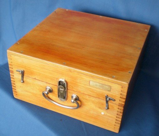
Figure 1 : Exterior of case
La Filotecnica was founded in 1865 by Ignazio Porro ( 1801 – 1875), the inventor of the prismatic binocular. Porro served in the Italian Army before retiring with the rank of major, in 1842. He worked in Paris for about fifteen years, producing a variety of surveying and optical instruments before returning to Italy in 1861. He founded the Officina Filotecnica at first in Turin and then, in about 1865, in Milan. The factory combined production with what we would probably call nowadays a school for apprentices. Porro seems to have had a poor head for business and in 1870 one of his pupils, Angelo Salmoiraghi (1848 – 1939), took over the ownership of the business after a short period in management. Under Salmoiraghi as La Filotecnica Salmoiraghi, the firm became one of Italy’s leading producers of optical and precision instruments. Today, the firm, trading as Salmoiraghi e Vigano, manufacturers principally spectacles and markets optical goods made by other firms..
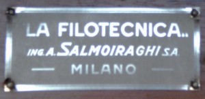
Figure 2 : Name plate.
Opening the case reveals a clever way of retaining the sextant in the case. Unusually, the instrument can be placed directly in the case without letting go of the handle. A further very practical aspect to the design of the case is that the sextant can be replaced with the telescope in place. Closing the lid brings pads of very fine brown felt into play to secure instrument and accessories securely in place. A finely crafted stand receives the sextant, location being ensured by large wooden spigots that fit into the circles of the frame, while the telescopes fit into well-thought-out pockets (Figure 3).

Figure 3 : Contents of case
The mirrors, shades, the index arm and its bearing are all conventional. The horizon mirror is fully silvered so that the horizon is viewed viewed directly, without passing through an unsilvered part of the mirror. This would be a disadvantage with a Galilean (so-called “star”) telescope, in which each half sees its own field of view, so that without reflection from the clear glass of a half silvered mirror there is little overlap of the direct and reflected images. However, this sextant is provided only with a 6 x 30 mm prismatic monocular and a 10 x 17 mm inverting telescope, both Keplerian in principle, so that there is very adequate overlap of the images. There is a sighting tube for use when surveying or taking sights in heavy weather. In what follows, I will describe only what is unusual or unconventional.

Figure 4 ; Frame of sextant.
The bronze frame (Figure 4) is of about 162 mm radius and is of three-circle pattern. It resembles superficially the three-circle instruments of Hughes and Son (see my post of 18 Feb 2010) and of C Plath (see my post of 24 Jan 2010) but there are differences in detail. It is heavier than other frames of its radius, weighing in at a hefty 750 G compared to the Hughes frame of 600 G. Sailors who like a bit of “heft” in their sextants will not be disappointed by the Filotecnica as, equipped for viewing with the monocular, it weights 1750 G (3lb 14oz) versus the Hughes at 1500 G (3lb 5 oz). Both are equally and very resistant to flexing. With the exception of the arc, which is chromium plated, the face of the frame is painted semi-gloss black, while the rest is painted in a black wrinkle finish. The index arm bearing is attached with screws from the back.
In a general view of the instrument (Figure 5), one is immediately struck by the length of the micrometer shaft. Unlike almost every other sextant of this pattern, the micrometer worm is not tapered. While it is easier to make a cylindrical worm, the penalty is that either the micrometer drum has to be smaller to fit beneath the curve of the limb or the shaft has to be longer and therefore more vulnerable to damage.

Figure 5 : General arrangement, front view.
The worm shaft runs in plain parallel bearings mounted on a swing arm chassis, which pivots around the ends of two cone-pointed screws attached to the back of the index arm expansion (Figure 6). These latter screws can be adjusted to remove all end float and then locked in place. In this instrument, the release catch swings the worm at right angles to the plane of the arc (Figure 7), in contrast to most other sextants, which swing it out of engagment parallel to the plane of the arc. There is no adjustment for end float of the micrometer shaft, however, and absence of float, equally as undesirable here as in the swing arm chassis, depends entirely on skilled fitting, rather than using a preload spring like most other instruments .
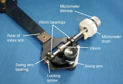
- Figure 6 : Micrometer mechanism

Figure 7 : Swing arm detail
Figure 8 shows how thrust in either direction is received on collars on the shaft and the inner ends of the plain bearings. Upon testing by directing an autocollimator on to the index mirror and approaching zero with the micrometer reading increasing and decreasing, I could detect no difference in the autocollimator readout, indicating a complete absence of measurable backlash (unwanted longitudinal shaft movement) with a precision of better than 1 arcsecond. This absence of backlash, besides indicating immaculate fitting of the shaft and bearings, is of course necessary to make meaningful the non-adjustable error readings shown in Figure 9. Almost needless to say, these are quite exceptional results for a micrometer sextant of 1948 date. The pitch of the worm is 1.4 mm giving a pitch circle radius for the rack of (1.4 x 720)/2 pi = 160.43 mm.
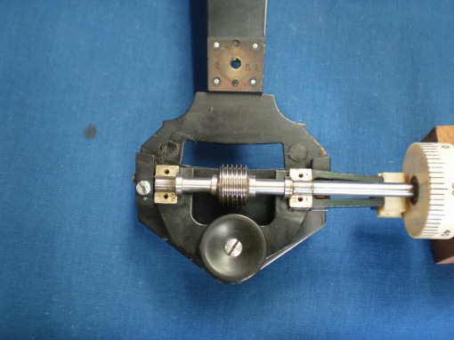
Figure 8 : Micrometer worm shaft bearings.

Figure 9 : Chart of non-adjustable errors
The method chosen to mate the telescope and sighting tube to the sextant seems somewhat over-engineered. The tubes are fitted with heavy brass collars that have coarse interrupted threads on the outside. The rising piece has the usual arrangement of a tiltable bush for collimating the telescope, with the addition of a large captive nut having a female interrupted thread on the inside. A stout pin projects from the face of the bush to locate in a hole on the telescope collar, so that the thread starts correctly and attaches the ‘scope to the rising piece with one sixth of a turn. Figures 10 I hope make this clearer.

Figure 10 : Telescope attachment
But there is further complication in the telescope bracket. It has a female vee into which the vee on the rising piece fork fits and a thumb screw to lock it into place, but there is also a captive thumbscrew whose thread passes through a short rectangular nut, to which is attached a leaf spring. In the end of the leaf spring is a hole that engages with a short nib on the rising piece. The whole is intended to act as a slow motion adjustment for the position of the rising piece (Figure 11). I have seen a somewhat similar slow motion adjustment on a 1940s Tamaya that is an almost exact copy of a pre-war C Plath instrument and may even be a C Plath, sold to have a Tamaya trade mark added. Most post WW II sextants of course managed very well without this complication.

Figure 11 : Exploded telescope mounting
The whole arrangement strikes me as being at the same time clumsy and yet an elegant solution to a problem that did not really exist. It must surely have been cheaper simply to provide each scope and tube with its own rising piece, manufactured so that no collimation adjustment was necessary, as was done for the prismatic monocular (Figure 12). This could surely have posed few problems for a factory capable of achieving the almost impossibly precise fit of the micrometer shaft bearings.

Figure 12 : Monocular and its rising piece.
The battery handle also shows an elegant and complex solution to a relatively simple problem (Figure 13). The positive pole of the single AA cell makes contact with a screw head to which is soldered the wire to the lamp. The negative pole makes contact with the lid of the compartment via a spring. The hinge of the lid is attached via a tongue let into the side of the handle and the tongue is prolonged as a piece of brass rod with a switch contact on the end. A second piece of brass rod (shown dotted in brown) with a similar contact passes through a hole from above and a single screw that attaches the upper pillar passes through a threaded hole in the rod. When the switch button is pressed, the contacts are bridged and current flows from the negative pole to the frame of the sextant, completing the circuit to the lamp. A second screw , which does not form part of the circuit, passes through the handle into a threaded hole in the upper pillar base and the head of the screw forms the third point of rest when the sextant is set down with its face up. How the very narrow slot for the tongue that attaches the lid was made still eludes me.
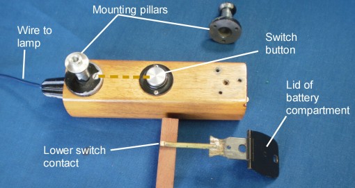
Figure 13 : Battery handle
The over-all impression is of a very finely made instrument having some unnecessary complications. It cannot have been cheap to produce, but professional mariners continued to pay a premium for perceived quality even when cheaper instruments able to do the job just as well became available.
If you enjoyed reading this post, you will very likely enjoy reading my book, which goes into similar detail about the structure of The Nautical Sextant.


You must be logged in to post a comment.