I have placed this post in the Aircraft bubble sextant category because, although the C Plath bubble horizon instructions imply that it can be used at sea with a nautical sextant, this is not the case. Bubble horizons are of use on land and in the air, where accelerations either do not occur or occur in a well-understood way. However, accelerations at sea are too great and unpredictable for them to be useful, except perhaps on a very large vessel in calm waters or in ice where no horizon is visible. In 1960, the German Navy was supplied with these attachments as were US submarines. It would be unsurprising if they were never used on aircraft, as much better, dedicated aeronautical sextants had long been in use (see Comment by Dr Andreas Philipp).
This post is preceded by “A gummed up AN5851-1 averager”, “Bubble illumination of Mk V and AN 5851 bubble sextants” , ”Refilling Mark V/AN5851 bubble chambers” , ”Overhaul of MkV/An5851 bubble chamber” , ”AN5851-1 : jammed shades carrousel” , ”A Byrd sextant restored” , ”Update on Byrd Aircraft Sextant”, “A nautical sextant bubble horizon” and “Sealing A10 vapour pressure bubble chambers.”
When C Plath resumed sextant production in the early 1950s, they applied their experience with the SOLD bubble sextant to designing an artificial horizon attachment for nautical sextants. They had been instrumental in producing a bubble sextant for Admiral Gago Coutinho of Portugal, who made several long over-water flights in the 1920s, but that sextant was an adaptation of a nautical sextant employing two linear spirit levels at right angles to each other, both of whose bubbles had simultaneously to be aligned with the observed body. The SOLD sextant had a circular bubble chamber, adjustable in size, and contained in a rigid bronze casting. The bubble unit used in the attachment for the post-war nautical sextant was based around a bubble unit almost identical in design and execution to the SOLD units. Figure 1a shows a general view of the units, while Figure 1b shows the bubble chambers from above, with the SOLD-type units on the right. Figure 1 c, from a war time manual shows a slightly modified design that is clearly the same design as the post-war unit.

Figure 1a : General view of bubble units

Figure 1b : View of bubble chambers from above.

Figure 1 c : Drawing of bubble unit (modified from SOLD manual).
When the adjusting screw is rotated anti-clockwise, the bellows are compressed and the pressure in A rises. It is transmitted via the drilled passage 1 to the bubble chamber and, if the bubble lies correctly within the triangle etched on the glass at the front of the unit, air is forced into the air chamber and the bubble size decreases. Conversely, if the pressure in A is caused to fall by rotating the adjusting knob clockwise, air is drawn from the air chamber, via passage 2, into the bubble chamber. The correct position for the bubble when observing is shown by a central square. In use, to adjust the bubble size, the sextant is tilted backwards to bring the bubble within the area marked by the triangle. After long storage, the bubble chamber may be nearly empty but nearly always this seems to be that the air and the fluid , alcohol in the SOLD, redistribute themselves, rather than being due to leakage. In this case, most of the fluid can be shaken out of the air chamber by repeatedly flicking the wrist with the air chamber upper-most. The air in the fluid chamber can then be displaced into the air chamber by patiently rotating the control knob slowly back and forth with the triangle up, until the bubble reaches the required size.
Figure 2 shows the ray path through the attachment. Rays from the observed body are deflected by the horizon mirror of the sextant into a window in front and pass through a semi-reflective mirror into a 3 power Galilean telescope. The bubble formed in the bubble chamber above lies at the focus of a concave mirror below, so that rays forming the image of the bubble emerge from the mirror parallel, and the image of the bubble appears, like the observed body, to be at infinity. These parallel rays are deflected by the semi-reflective mirror (in fact a piece of plane, unsilvered glass) into the telescope. Thus, the image of the bubble is superimposed on that of the body and it lies to the observer simply to bring them into coincidence, a by-no-means-easy task.

Figure 2 : Ray path through attachment.
The bubble chamber is illuminated above by a bulb contained in a screw-on holder. Light from the bulb is diffused by a red diffusing screen (Figure 3) and its intensity varied by a variable resistance (“potentiometer” or “rheostat”) of about 10 ohms resistance. If the bulb is replaced by an LED, then the potentiometer will also need to be changed for one of about 1000 ohms, as described for my first post of September 2013.

Figure 3 : Bubble illumination.
Power for the lamp comes from the battery handle of the sextant. Current flows through the plug and lead to the wiper on the variable resistance (black wire, Figure 2) and thence to the brass ring (red wire) in the top of the attachment. The ring is insulated from the body of the attachment and, when the bulb holder is screwed home, another, brass ring, threaded for the bulb and insulated from the bulb holder, makes contact to carry the current to the bulb. The return current is carried from the central contact of the bulb to the body of the bulb holder, through the body of the attachment and thence, via the mounting fork, to the body of the sextant.
There is no provision for illumination of the bubble by daylight, so for sun observations, the shades of the sextant are dispensed with and a dark shade attached to the front window, so that the bubble can be seen at the same time as the sun. For star and planet observations, of course, no shades are used with the sextant or the attachment. Daytime moon observations may be possible by removing the attachment’s shade and obscuring the horizon with all the sextant’s horizon shades and by using an index shade that just allows the moon to be seen, but I have no personal experience of this. The unit was originally supplied with only one shade.
I am grateful to Murray Peake for entrusting me with the overhaul of his attachment.
Postscript
To expand on the paragraph after Figure 1c, when the bubble cannot be reduced in size, and small bubbles seem to enter the chamber at random:

Postscipt 1: Beginning of swing. Note position of unit in the hand.
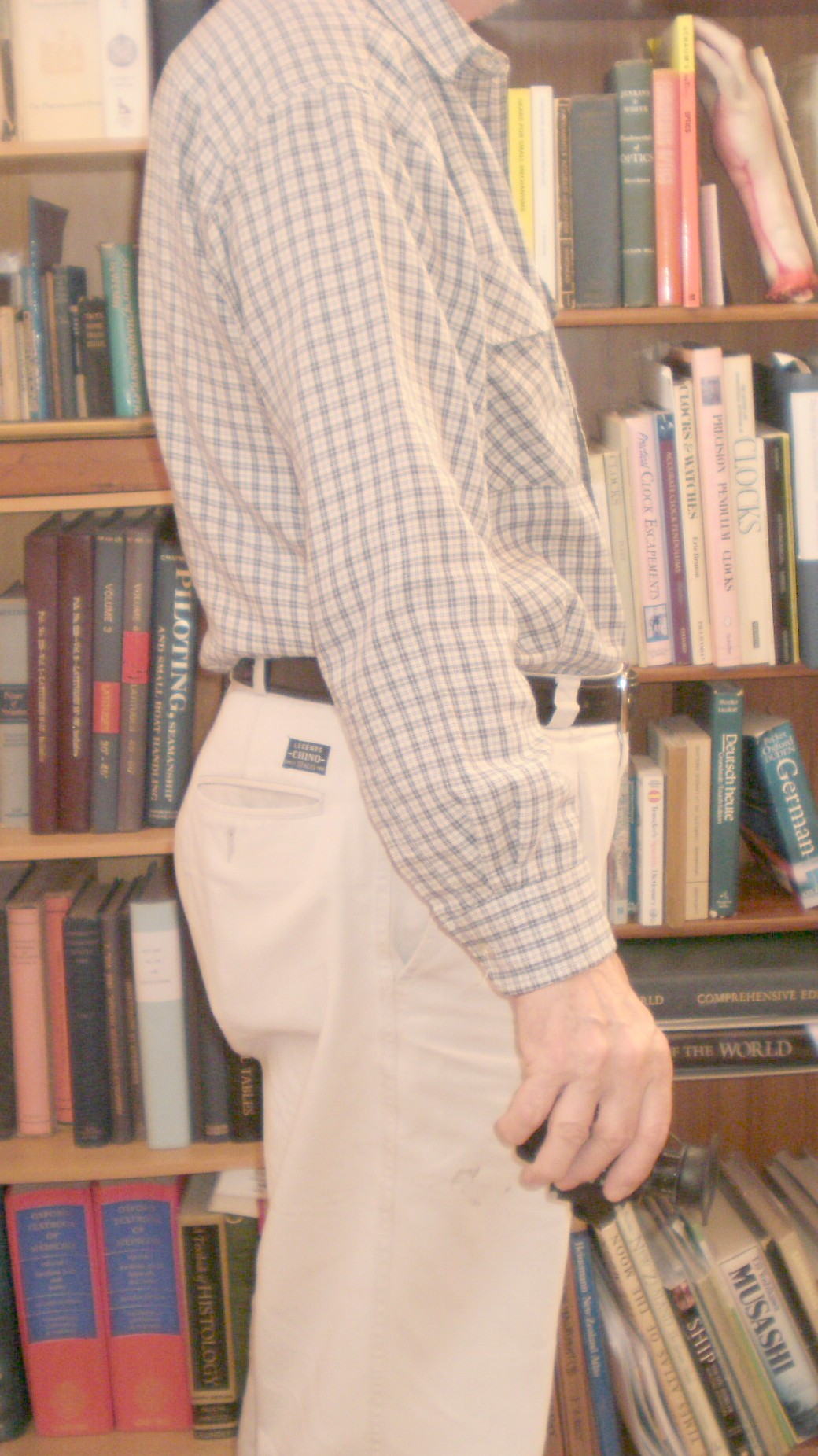
Postscript 2: End of swing.
3 October 2014. Patrick Fitzhorn writes:
“You may already know this, but I thought I would pass it on as it may be of interest to others. I have (finally) fixed my C. Plath artificial horizon telescope (similar to that as shown in 26 June 2012). Mine has been missing the primary telescope lens for several decades, rendering the whole thing useless. Years ago, I pulled the telescope assembly off, measured the inner diameter of the primary lens holder (29.2 mm), sized the secondary lens (a double concave), and then fired up a software tool for the design and analysis of optical lens systems for lasers. Looking at the telescope, it seemed pretty clear that the lens would have been an achromatic doublet (to minimize color distortion). I modeled the system in the software and found roughly that the focal length of the doublet would have been about 56 mm.
I then called the trusty large optical lens maker in Denver, CO who said they would finish sizing the primary, and then because an achromatic doublet has four finished surfaces (both sides of two lenses then glued together) the lens would cost $4,000 US. They would do the lens analysis for free!
Aha I thought. I’ll just buy the lens from one of the two major US lens suppliers – Edmund Optics, or ThorLabs. BUT – the closest I could come to off-the-shelf optics (at $80 to $120 US) was 30mm D and 60mm EFL. Wouldn’t work.
I then carefully shelved the project.
Just recently, I picked the project back up, thinking there must be some other solution. I figured there might be cut-rate optical companies with odd sized lenses, and surfing the web (like any good sextant soldier) I found two within the US. One with student-quality lenses at $4 to $8 US in a huge variety of sizes. The other with coated quality optics, less sizes, and a range of $20 to $30 US. From the cheaper company I ordered 5 lenses with diameters within +0 and -2mm from my 29.2mm, and focal lengths from 45mm to 100mm. One at a time I tried them in the telescope, finding that a 60mm EFL was a bit too long, and 51.77mm quite a bit short. Using the 51.77mm set to good focus on the moon, I measured the telescope length with calipers. I then turned the focuser out until the tick marks lined (where it should have been in focus) and remeasured. The difference was 5.08mm – an ideal EFL of 56.77mm. From the more expensive company I found a 58mm D achromatic doublet with 57mm EFL for $22 US.
Got it, installed it, cleaned it up, tried it – works great. I now have my artificial horizon. By the way – the story of how the primary was lost will take longer than this discussion!”
http://www.surplusshed.com is a good source of surplus lenses of all shapes and sizes. Knowing that the magnification of the telescope is 3 times, the focal length of the objective lens could be deduced if the focal length of the negative (concave) eye lens could be discovered. You cannot of course cast an image on to a screen with a negative lens, but a rough idea of its focal length can be had by combining it with a positive (convex) lens of known focal length and greater strength, so that the combination is positive, and then casting an image of a distant object on to a screen and measuring the focal length directly. The sums are slightly easier if you take the lens’ powers in dioptres, the inverse of the focal length in metres. Then, if you combine, say, a 10 D positive with a 5 D negative, the power of the combination is + 5 D. Once you know the (negative) focal length of the eye lens, -f ,and the magnification, m, the required focal length of the objective lens is – -f x m or f x m. A quicker alternative is to take the negative eye lens to your friendly local optometrist to have its focal length measured in less time than it takes to write this sentence. WJM


You must be logged in to post a comment.