A Freiberger scale illuminator

9 06 2020

Julian Thornton recently wrote to me about his newly acquired Freiberger Trommelsextant , asking about a fitting attached to the outside of the micrometer mechanism. He was able to de-construct it to get it working and kindly agreed to write a guest post. This is what he wrote (I have added comments in blue):

I bought a used Freiberger Trommel sextant on eBay and when it arrived it had an attachment on the micrometer drum (Figure 1)

Lighting GA on sextant

Figure 1: Lighting unit as found.

At first I didn’t know what this was (this was my first sextant) but eventually worked out that it was a lighting unit.  It didn’t work so I decided to take it apart. An exploded view of the disassembled lighting unit is shown below (Figure 2). This figure can be enlarged by double clicking on it. Use the back arrow to return to the text.

Lighting exploded

Figure 2: Lighting unit exploded.

The frame of the unit wraps around the micrometer housing of the sextant and is held in place by a thumb screw (see also Figure 4). The bulb screws into the bulb housing.The contact rod is insulated  from the bulb housing by the insulating bush. The bush screws into the other end of the bulb housing. A  screw  passes through the switch arm into the end of the contact rod. The other end of the switch arm is secured by a screw which passes through an insulating bush into the right hand end of the battery housing to make contact with the battery. When bulb end of the arm is depressed, the end of the contact rod makes contact with the central contact of the bulb. The circuit is completed via the spring, cap, battery housing, frame and bulb housing into which the bulb screws.

This unit would not be too difficult to reproduce in a well-equipped home workshop. I may try to do so when I run out of other things to do...

The first thing I did was put a new AA battery in it but it still didn’t work. I inspected the bulb but I couldn’t see a filament, but as I didn’t have a circuit tester with me I could not test its continuity. On the side of the bulb it said 1.5v 0.2A so I looked online and found that E10 1.5v 0.3A bulbs are pretty common so I bought some. I also noticed that the original bulb appeared to have thicker glass of the top than the sides, almost as if it were a crude lens, see bulb on the right in the picture below (Figure 3).

Lighting bulbs

Figure 3: New and old bulbs.

The old bulb with its lens is called a pre-focus bulb

I emailed Freiberger in Germany to ask about the bulb and ask if they sold spare bulbs. They confirmed that the bulb does indeed have a thicker end than sides but that they do not sell spares of any type for the illuminator mechanism, but that I could buy a complete new unit for €136  plus postage and packing. They said that a standard E10 1.5v bulb would work fine. I then cleaned up all the contacts and reassembled the unit with the original bulb. The light came on immediately and the unit worked well with the on / off function provided by pushing the metal screw at the end of the lamp assembly which then makes the electrical circuit, see LHS of end view below, Figure 4. The natural tension of the metal plate connecting the battery and lamp assemblies then moves the screw away thus breaking the electrical circuit.

This photo also makes clear how the unit is attached to the sextant.

Lighting switch

Figure 4: End view of switch.


When the new bulbs arrived I inserted one and it came on immediately but the only way I could turn it off was to remove the battery. On further examination of the new and old bulbs I noticed that the new bulb was fractionally longer so I filed down the contact end of the bulb with emery paper and re installed it. The unit then worked properly. The new bulb is rated at 0.3A so in fact is a 50% higher power rating than the original bulb and is a noticeable improvement.

Thank you, Julian.


Freiberger Drum Sextant (Trommelsextant)

10 08 2011

This post is preceded by one on the Freiberger Yacht sextant and two on the Freiberger Skalensextant

Readers looking for a manual that helps with maintenance and repair of the Freiberger Trommelsextant (drum sextant) will find my SNO-T Sextant Manual very useful, as the design of the one is based on the other. While the manual describes the SNO-T, it also gives an account of the Freiberger drum sextant where its design details differ. See under “The USSR SNO-T sextant” and “Buy”

The firm of Freiberger Präzisionsmechanik has been in existence since  late in the eighteenth century and by the 1870s had a large workshop employing over eighty people in the manufacture of surveying instruments. At the end of WW II it was overrun by  Soviet forces and dismantled, leaving only fifteen workers to carry out maintenance on surveying equipment. It was refounded in 1950 and in that decade the trommel sextant was developed. As far as I know, the firm had never previously made sextants.

The sextant is unusual in several respects. While the over-all shape and placement of shades and mirrors is conventional, it has a die-cast aluminium alloy frame, which combines lightness with a strength and hardness near to that of mild steel. The ladder or three circle patterns of its main competitors were ignored. Material is concentrated around the edges and the whole stiffened by a central web (Figure 1). The worm runs in a rack machined directly into the edge of the limb, thus avoiding the complication of attaching a bronze rack to an aluminium frame.  The substantial but unseen bronze worm seems to run very well against the alloy rack.

Figure 1 : Freiberger drum sextant, front view.

The very substantial index arm lies behind the web of the frame and is bridged by a casting to which is attached the handle (Figure 2). The upper end of the index arm is screwed to a large diameter bronze journal (the part that rotates in a bearing) that rotates in a bearing machined directly in the frame, thus abandoning the narrow, tapered journal and bearing in use since the third quarter of the eighteenth century. C Plath later dallied with such a bearing in their bronze-framed instruments, but they soon reverted to the tapered form.


Figure 2 : Freiberger drum sextant, rear view.

 The micrometer mechanism is concealed within an alloy casting attached to the lower end of the index arm. The cylindrical worm runs in eccentric bearings in a bronze casting that itself rotates against the force of a helical spring in bearings machined in the alloy casting. Thus, when the bronze casting is rotated, the worm swings out of engagement with the rack. The closeness of this engagement can be adjusted by means of a tangential screw whose head is just visible in Figure 2 to the left of the drum. While Freiberger chose to swing the worm out of the plane of the rack, nearly every other maker swung it out of engagement in the plane of the rack, following the pattern devised by C Plath in about 1907.  The latter method must certainly have been cheaper to manufacture, even allowing for the unecessary complexity of the worm shaft bearings in some pre-war marques. However, Freiberger’s method totally encloses the worm and solidly supports the shaft at both ends, so it is hard to imagine the shaft getting bent by an accidental knock, as had happened to at least three conventional instruments that have passed through my hands.

The sextant was usually provided with a 3½ x 40 Galilean telescope only. My own instrument has a 7 x 35 monocular, which gives a superior field of view as well as making the point of coincidence of the body with the horizon easier to determine. The vee and flat of the mounting are the reverse of all other makers, so their telescopes cannot be interchanged.

The USSR imitated Freiberger’s design in their SNO-T sextant, albeit in an instrument of slightly smaller radius and one provided with an unusually full complement of tools and spares. The edge of the SNO-T frame is  8 mm thick (compared to 3 mm), making it an even more rigid and robust instrument than the Freiberger. The bare sextants weigh 1300 and 1200 grams respectively.


Freiberger Yacht sextant

24 06 2011

This post is preceded by “Inside the Freiberger Skalensextant” and “The Freiberger Skalensextant.”

Freiberger Präzisionsmechanik of the then German Democratic Republic, produced three sextants over the years: the uncommon Skalensextant; their main line, the Trommelsextant, aimed at professional navigators; and in the late 1970s they introduced their Yacht sextant. The latter was aimed at “Western” yachtsmen in competition with Plath and Tamaya at a price of around US$600, when a full-sized sized sextant by these makers could scarcely be had new for under US$1000. It had few features in common with its big brother, the Trommel or Drum sextant which retailed for about US$200 more, but presumably the pressure die cast aluminium alloy frame with rack cut directly into it, that they both had, was one feature that enabled Freiberger to undercut their Western rivals, or it may be that they were heavily subsidised.

Another feature which is also unfortunately in common with the big brother is that some examples have large arc errors, sometimes up to 90 seconds. As the arc is calibrated every ten degrees, it is not difficult to make a graph of the errors to help in applying corrections. Others would argue that on a pitching and rolling yacht, errors of observation are likely to swamp errors of the instrument. Many Freiberger instruments, it must be said, have the negligible errors of their competitors.

In a contemporary handbook, written in a charming Engleutsch, the Yacht sextant was “destined for use on sporting and luxury ships… with conditions and requirements for accuracy …completely maintained though weight and volume of sextant have been reduced  down to approximately half their former values. In consideration of aspects of beautiful shape and representativity, graduated arc and arc webbing have been modified that dimensional stability at extreme temperature differences and mechanical stress can be expected at the same time.”

In my description that follows, I will comment mainly on points that distinguish this sextant from the conventional, touching only briefly on parts that follow standard practice.

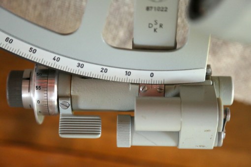
General arrangement (Figure 1)

The frame is certainly austerely functional and the limb has a radius of 142 mm against that of the drum sextant, which is about 170 mm, while its weight with its permanently mounted telescope is 860 G, compared to, say, the 1300 G of an alloy-framed Tamaya with a star telescope mounted. There are only three index shades and two horizon shades, quite enough for most purposes. The mirrors, which are interchangeable, both measure 59 x 29 mm. This is not the advantage that it might seems, as the horizon mirror is fully silvered, that is to say, there is no plain glass half, the horizon being viewed directly rather than through a thickness of plain glass. The edge can be fully protected with paint, whereas the junction between the silvered and unsilvered parts of the traditional mirror was always a weak point for sea water to attack the silvering. However, each half of a Galilean telescope “sees” only its own field of view: if half of the objective lens is covered over, half of the field of view is lost. With the traditional arrangement of mirrors, some of the light from the index mirror is reflected off the front surface of the plain part of the horizon mirror into the telescope, so that the images of the body and of the horizon to a large extent overlap. In this instrument, with the fully silvered mirror and a Galilean telescope, there is overlap of about one sun diameter (about half a degree) as opposed to about two and a half diameters for a full glass, and this may make for difficulties for  an inexperienced or occasional observer.

Most modern sextants seem to have Galilean telescopes with about x 4 power with an objective of 40 mm, while the Yacht sextant has one of x 2.4 power, with an objective of 22 mm, so the field of view is about the same. Early yacht sextants had ordinary, second surface mirrors. One that I have seen from 1985 has first surface mirrors which give a slightly brighter image, imperceptible to the eye (which can just detect a doubling in brightness), but at times of poor contrast between the sky and the horizon, even small differences in brightness can make for a useful increase in contrast.

Figure 1 : Front view of Yacht sextant.

The arc is a  sliver of screen-printed aluminium secured to the frame with glue and two pins which, rather surprisingly are made of steel. Predictably, in my example which had seen a lot of sea use, they had rusted and the glue had also given way. The telescope is a 2.4 x 22mm Galilean that focusses by rotating the objective lens mounting rather than the eyepiece and is  less prone to go out of focus as the eye presses against the scope. The eyepiece is provided with a deep flexible rubber pad, a perhaps necessary adjunct for a lightweight telescope used on board a pitching and rolling yacht.

Figure 2 : Rear view of Yacht sextant

The rear view (Figure 2) shows that Freiberger retained the same arrangement for the index arm as in the Trommelsextant (and the Soviet SNO-T) siting it behind the frame out of harm’s way. To avoid having to have a bridging piece, the black anodised alloy handle is attached to the frame only at the top, by three screws. The release catch at the lower end of the index arm swings the worm out of engagement in the plane of the rack and, as will be seen, has a much simpler (and undoubtedly cheaper) arrangement than in its larger brother.

Index arm bearing

Figure 3 : A cornucopia of screws.

Removal of the handle reveals a sextet of screw heads beneath. Two pass through the bearing (strictly speaking, the journal) and attach the index mirror mounting to the deep flange on the other side. Four attach the index arm to the journal (journal : the part of a shaft that is enclosed by a bearing). Removing these allows the journal to be withdrawn. The fit is necessarily a very close one and care has to be taken that it does not capsize and jam. Figure 4 shows the bearing dismantled and it is seen that the large parallel bronze journal runs directly in the frame. There is no provision for taking up wear as none is to be expected in a slow-moving part with such large bearing surfaces.

Figure 4 : Index arm bearing details.

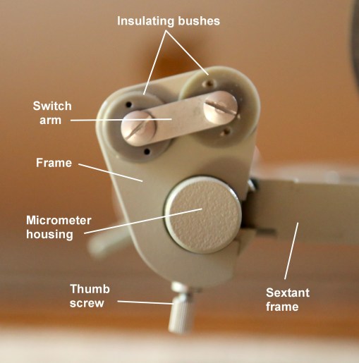
Worm and release catch

The Trommelsextant swung the worm out of engagement with the rack by having a relatively complex eccentric bearing that rotated the worm in its bearing out of the plane of the rack. Elegant though the method was, it must have been very expensive to produce. In the Yacht sextant, Freiberger have managed to give a large degree of protection to the worm by enclosing a substantial bronze swing arm with integral worm shaft bearing in a U-shaped alloy casting, that is attached to the index arm via a tongue and three screws (Figure 5). The shaft, immediately on emerging from its bearing, is enclosed by the micrometer drum and the knob for rotating it, so that a common consequence of dropping the sexant, a bent worm shaft, is avoided.

Figure 5 : Worm enclosure

The release catch is a cranked metal stamping. When it  is operated, its end bears on a pin that passes through an oval hole in the enclosure casting into the swing arm, and presses the swing arm down agains a leaf spring that lies between the swing arm and the bottom of the casting. Upon detaching the casting from the index arm, some more details are revealed (Figure 6).

Figure 6 : Swing arm from above.

The bronze swing arm rotates about a pin for an axis (seen in Figure 5) and has a long and substantial bearing for the worm shaft. End float of the latter is prevented by trapping the worm between an L-shaped phosphor-bronze  pre-load spring and a PTFE washer. The aluminium alloy drum, divided into minutes and attached to the knob by two screws, was heavily corroded and pitted in my example, and I was obliged to make a new one.  The knob is retained on the worm shaft by a grub screw and a pin nut. Figure 7 perhaps allows a better appreciation of the internal workings of the release catch and swing arm.

Figure 7 : Side view of worm mounting.

Shades

The index shades are mounted directly into the frame, as shown in Figure 8.

Figure 8 : Index shades mounting.

They are mounted on a screw that has a longitudinal key way machined in it. The screw passes through a narrow tongue of the frame, through the shades and separating washers, through a Belleville washer (a washer having the characteristics of a short, stiff spring) and finally into the body of the frame. The separating washers have an integral tongue that fits into the keyway, so that forces from the rotation of one shade cannot be transmitted to the next. The Belleville washer provides enough friction for the shades to stay in the positions in which they are put. It might be thought that the friction could be varied by tightening the screw, but a transverse steel (!) taper pin prevents it from rotating. Driving it out places at risk the slender tongue of the frame which would pose great problems to replace it, if broken off.

The two horizon shades are mounted on a shouldered screw which also has a keyway and the separating washer also has a tongue that fits into the keyway to prevent it from turning  (Figure 9). The screw is driven into a mounting block hard against its shoulder and it is only this that prevents the screw from undoing. A Belleville washer between the rearmost shade and the mounting block provides friction. Close inspection of Figure 9 shows that over time the convex side of the washer wears into the soft metal of the shade, resulting in loss of friction and a very annoying tendency for the shades to flop downwards out of position. This can be countered  by means of a thin shim washer, whose internal diameter must be a little greater that the diameter of the unthreaded part of the screw, and care must be taken that the shim does not get trapped between the shoulder of the screw and the mounting block. Alternatively, the height of the Belleville washer can be increased slightly by making a depression in the end grain of a block of hard wood using a 12 mm ball bearing, resting the washer in the depression, placing the ball bearing on top and hitting it smartly with a hammer. This is likely to make the ball fly off into a remote recess of the workshop, but as it cannot now be reused for any other purpose, the loss is not a great one. When replacing the shades, they and the washers are mounted on the screw and it is started into position, with the concavity of the Belleville washer facing the mounting block. If the sextant is held with that washer facing upwards, it is then possible to wangle the hole in the washer over the shank of the screw before driving it home.

Figure 9 : Horizon shades mounting exploded.

Adjusting screws

The screws themselves are standard M2 screws with squared heads. They pass through  split collets that are threaded on the outside and which screw into bosses projecting from the back of the mirror mountings. Each collet has a tapered tip that fits into a matching female taper at the bottom of the boss, so that when the collet is tightened, it closes up around the screw, thus increasing the resistance to the screw’s rotation or locking it if required (Figure 9). There is a clearance hole through the mirror bracket for the screw

Figure 10 : Adjusting screw, collet and tool.

Though the adjusting screws for the SNO-T and the Freiberger Skalensextant are superficially similar, anyone who treats them the same is in for an unpleasant surprise; and jammed, broken or stripped screws are a common occurence. In these sextants,  the collets, which have coarse threads on the outside are not split, and the adjusting screws pass through threaded holes both in the collet and in the back of the bracket. The screws are locked by unscrewing the collet a little.  The screw can be withdrawn by rotating the collet a little to find the position at which the screw is unlocked. Any attempt to fully unscrew the collet before the screw has left the thread in the mirror mounting inevitably causes damage. Some early Trommelsextants may have the same arrangement, so it would pay to proceed with caution if backing off the nut by half a turn does not release the adjusting screw.

If you have enjoyed reading this account, you will I am sure enjoy reading my book, The Nautical Sextant, available through booksellers, from Amazon or direct from the publishers, Paradise Cay and Celestaire.


Inside the Skalensextant

4 04 2010

In a post about a year ago, I gave an introductory description of this unusual sextant, that uses a glass scale moving past the optics of a micrometer microscope to give a rapid readout in degrees and minutes. Recently, a correspondent in France met one of the same problems as I had, that of being unable to view the degrees scale, and asked me how he could get at the optical system to clean it. Sometimes I am guilty of thinking that what is clear to me is clear to everyone else, so here is a blow by blow account of how to get at the hidden insides of the Skalensextant. The mirrors, shades and telescope are conventional and need no special description.

First, remove the handle by undoing two screws as shown in the photo that follows:

This allows access to the back of the index arm bearing and “index” arm. I’m putting index in inverted commas just this once, to recall that it is not strictly speaking an index arm, since it carries the scale that moves past a fixed index in the viewing microscope. You need to remove the index arm by removing a grub screw…

…and then unscrew what we have to call a bolt (since it is a screw with a shaped head), although the term seems out of place in the context of instruments.  If you now operate the release catch, it allows you to wriggle off  the index arm from the index arm shaft, given its proper name of journal in the photo. Notice that the grub screw has rather a ragged slot. If you find a grub screw in this state, either replace it or file it smooth and cut a new slot. If it loses its head at the bottom of a hole, it can be very difficult to remove without drilling it out and possibly damaging other parts in the process.

The rear cover can now be removed by undoing six screws as circled in the next photo. You do not need to remove the horizon mirror. Note at this point the little cover held on with two screws, just below and to the right of the upper middle cover screw in the photo.

You can now take a look inside the sextant, but I won’t repeat the description given in the previous post.

Next to come off is the little dovetail slide to which is attached the lighting system. This allow access to the two cheese headed screw that hold the objective  assembly to the frame. Remove these two screws…

…and lift out the assembly.

The prism carrier is attached to the objective assembly body by two screws, only one of which has been removed in the next photo because the other one defied all my non-destructive efforts to loosen it. Fortunately, the two right-angle faces are now accessible for cleaning, and traces of rouge that I used to clean up the very heavily soiled lens faces can still be seen on the carrier. Since I could not detach the prism carrier from the rest of the assembly, I was not able to release the prism to get at the hypotenuse face, by my normal method of slowly heating in water from cold until the shellac melts. I give an account in the previous post of why it was necessary to remove what was left of the silvering on the hypotenuse face and how I did it. If after cleaning the other faces, it is possible to get a clear view through the prism, there is no need to touch the third face.

Re-assembly is the reverse of dis-assembly.

Returning now to the little round cover noted above, its removal allows access to the focus adjusting screw. To bring the main scale into focus, first adjust the micrometer eyepiece until the minutes scale is sharply in focus. Then loosen the screw a little until it and the attached objective lens can slide in its slot. Move it back and forth until the degrees scale come into sharp focus. Only one number will be in coincidence with the minutes scale at a time. This reduces ambiguity, but makes it a little difficult to find an out-of-focus degrees number. When you think you have both scales in focus, check that the degrees marker does not move at all over the minutes scale when you move your head a little from side to side (the parallax test), and when you are satisfied, tighten the screw and check again.

In order to buy a copy of my book ,The Nautical Sextant, see the details in “Buy the Book”


Freiberger Skalen Sextant

22 03 2009

Recently, I was lucky enough to come across a very rare and unusual sextant made by Freiberger Prazisionsmechanik in 1958 at the height of the Cold War. The seller had been unable to fathom out how it worked. It came to me in the battered original box, which was devoid of all traces of glue and which appeared to have been sitting at some time in a pool of water. You will have to imagine what the outside looked like when I received it, but this is what it looks like now:

ga1

There are some familiar parts  like an index mirror that rotates when the release catch is released and swung, but the slow motion knob didn’t work, there is no scale or micrometer to be seen and on looking through the lower eyepiece, there was nothing to be seen. The seller had thrown in a telescope, but on examination it appeared to have been no closer to Freiberg than M’bai and showed signs of having possibly been turned using a blunt nail as a tool. The wonder was not that it worked poorly but that it worked at all. The only piece of the original left after restoring was the conical casting and the objective lens. Everything else had to be replaced by newly machined parts.

Even before receiving it, I had formed an idea about how it might work, as I had seen a picture of it on page 69 of Peter Ifland’s Taking the Stars. On dismantling it (none too simple a task), this is the view of the interior that greeted me:

skalen-sextant-as-recd

The back of the instrument had been sealed to the frame by some sticky waxy material but it had failed to prevent moisture penetrating. After further dismantling and cleaning, it looked like this:

after-cleanup2

Light enters through the translucent white window and passes through a glass scale attached to what I will call the index arm though it carries no index. It is then diverted through 90 degrees by a small prism into the objective lens of a low-powered microscope so that the scale can be viewed by means of the eyepiece. The trouble was that even when I had cleaned the scale, I still could see nothing through the eyepiece. I dismantled the latter and found a graticule that was opaque with dirt and once I had cleaned that, I could then see that the graticule contained a linear scale divided into sixty parts. A view of the main scale still eluded me until  I examined the prism – after a fashion – as I could not release it from its mount to which it was solidly attached by corrosion and, probably, shellac. At least I was able to see that the hypotenuse face had at one time been silvered and painted over, but the paint and silver had corroded. Now if the hypotenuse face had been left plain, the prism would have worked just as well, provided it remained clean. If the silver corrodes or the face receives a dirty thumb print, the totally internally reflected image is degraded, in this case, completely. Restorers of some American bubble sextants will have faced the same problem. I could not directly access the hypotenuse face, but I was able to patiently scrape off the paint and silvering with a sliver of brass shim stock, aided with slips of cigarette paper soaked in alcohol. It was then just a matter of adjusting the focus of the objective lens until an image of the scale came into focus at the same time as the graticule.

The main scale is divided into degrees and the eyepiece graticule is used to subdivide the reading into minutes. The glass scale was obviously de-centred, as the degree markers descended across the graticule as the degrees reading got higher. Happily, the instrument contains within itself the means of re-centring the scale. It can be released by loosening three screws that hold a substantial clip and heating the whole part up slowly to melt the shellac that is supposed to hold it where it is set. The scale can then be recentred by trial and error until every degree marker intersects the graticule to the same extent, and then fixed with something like Araldite.  This is the view through the restored optical system:

100_2672


The scale is reading 36 degrees 08 minutes. Peter Ifland says it can be read to 6 seconds, or one tenth of a minute. I think this is rather optimistic. It can be very rapidly read to the nearest minute and perhaps even to half a minute and, since the image is apparently at infinity, the eye does not need to refocus when changing rapidly from telescope to microscope eyepiece.

Glass scales were introduced into theodolites by the Swiss Heinrich Wild in the early nineteen twenties and it seems to have taken the rest of the world another quarter of a century to catch up. They are made by photographically reducing very large and accurately divided masters on to glass and etching the divisions . They are typically accurate to a  second, depending on the size of the scale. The one used in the Skalen (scale) sextant is of about 80 mm radius, roughly twice that of a T2 Universal theodolite.

In poor light, the scale can be illuminated by a fitting that dovetails onto the bracket below the lighting window (see below). Presumably, the original had as a power source something like a torch handle that sat in the user’s pocket, but it was absent from my instrument. In  daylight, it would benefit from a mirror to divert light from a bright part of the sky into the window, along the lines used in the popular Wild T2 theodolite. I plan to work on this idea (now successfully completed on 27 March 09. See photo below).

100_2605

Another feature of the Skalen sextant, at a time when nearly all sextants used tapered bearings for the index arm, is the very substantial plain parallel bearing, very similar, if not identical, to those found in the Freibergen Trommel (drum) sextants and the Russian SNO-T. Properly made and fitted, this should never wear out. The general workmanship is of a very high standard.

Dimensions:

End of eyepiece to front of horizon shades 260 mm; Top of handle to bottom of release catch 220 mm; Thickness of frame 30 mm; Height overall from back of handle to top of horizon shades 160 mm. Weight 1.6 kg; Index mirror 52 x 42mm; Horizon mirror half-silvered, 56 mm diameter; Telescope 3.5 x 40 Galilean.

Box dimensions 300 x 290 x 190

Here is the instrument alongside a Tamaya 632D for comparison:

size-comparison

It is not clear why this sextant never became popular. The principle is sound, the instrument is very rigid and weighs about the same as other sextants at  about 1.6 kg, it is easy to use and the slow motion device, once cleaned and lubricated, works well, without slippage or backlash. On the other hand, none of its features of difference give it an overwhelming advantage over conventional designs. Do let me have your thoughts on the matter.

I give brief details of this sextant in The Nautical Sextant.