A guest post by Arthur Leung
This post was preceded by “Hughes Marine Bubble Sextant”, “An improvised sun compass”, ” C Plath Sun Compass”; “A Fleuriais’ Marine Distance Meter” A Stuart Distance Meter”;“A Russian Naval Dip Meter”; and “An Improvised Dip Meter”
A little while ago I was idly reading and came across something called the Bygrave Position Line Slide Rule. Being already interested with things navigational, I started looking for more information about what this instrument was and how to use it. One thing led to another and before long I desired to make my own reproduction. To that end, I contacted Bill Morris with a request that he publish a blog post about his reproduction of the German version of the Bygrave manufactured by Dennert and Pape called the MHR1. Bill has added remarks in parentheses in italics.
(I had made the rule several years previously as a construction project and, having made it and tested it once or twice, placed it in storage.)
At the time I mostly hoped that he’d read my request and eventually write a post that covered the details of the methods he used to make his. Much to my surprise, he responded almost immediately and offered to send it to me to inspect. (For the most part, construction consisted of simple turning, sawing and filing)
I, of course, jumped on the offer. A few weeks later, this instrument arrived, very carefully packed.

Figure 1 Bill Morris’ fine work
Here are my musings that contains a little history, a little description, and a bit about using one.
Prior to the widespread introduction of modern sight reduction tables, a navigator would reduce sights by referring to books of trigonometric tables, reading them out, then adding/subtracting/multiplying them together, and then going back into the tables to extract an angle. For a 3-star fix, the amount of effort required would of course by multiplied by three. This can take a bit of time as it is a painstaking process. (When I started to take an interest in navigation more than forty years ago, in the (forlorn) hope that someone would invite me aboard a yacht for an ocean voyage, this is how I reduced my sights, using Burton’s Nautical Tables. Then sight reduction tables followed and finally I used a scientific calculator.)
The 1920s and 1930s saw aircraft capabilities in both speed and range increasing rapidly and, since aircraft can move considerably faster than a ship, a fix determined 30 minutes in the past is less helpful than a fix determined 5 minutes in the past. Thus, considerable effort by many people and institutions went into fixing the position of an aircraft more quickly.
Captain Leonard Charles Bygrave (RAF) at the Air Ministry Laboratories developed what would become the Position Line Slide Rule in the early 1920s. The motivation was to provide an air navigator a compact, lightweight, accurate enough, and fast means of solving the celestial triangle so the navigator could determine the altitude of the body (Hc) and the true bearing to the body (Zn).
The equations to solve the celestial triangle use trigonometric functions in combination. The equations themselves are shown below and were found on the following web site: Formulas (thenauticalalmanac.com).
Hc = sin-1[sin(declination) x sin(Latitude) + (cos(Latitude) x cos(declination) x cos(LHA)]
Z = cos-1[(sin(declination) – sin(Latitude) x sin(Hc)) / (cos(Latitude) x cos(Hc))]
Note that Z requires some additional, minor, manipulation to form Zn depending on the magnitude of Z and whether the assumed position is in the Northern or Southern Hemisphere but that is beyond the scope of this post.
In theory, a standard slide rule with the trigonometric functions on the face could be used to solve these equations. This method is more compact than the traditional method of trigonometric values taken from a large book of tables but still quite painstaking as each step needs to be recorded on paper, sums and products taken, additional sums taken, and then inverse trig values extracted.
Taking the slide rule idea slightly further, however, the scales of a slide rule could be created to enter assumed position and declination and then directly extract Hc and Z which would greatly simplify and speed up the process.
The problem with a linear slide rule is that, to get the required accuracy, the slide rule might be many meters long. The solution to this problem is to wrap the scales in a helix around a cylinder of modest diameter. In this way, the required precision could be attained while also having a reasonably compact instrument.
The Bygrave solution wraps a log-cosine scale around a middle cylinder and a log-cotangent scale around a slightly smaller, coaxial cylinder. The smaller cylinder has an outer diameter such that it forms a light friction fit with the inner diameter of the middle cylinder.
A third coaxial outer cylinder contains the two inner cylinders and holds the cursors to align the two cylinder’s scales, along with instructions to the user.
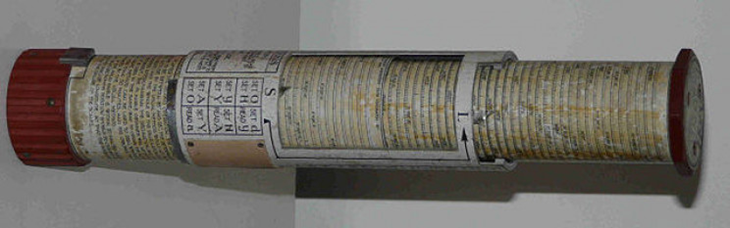
Figure 2 Bygrave Position Line Slide Rule
The helical log-cotangent scale length, when unwound, is 758.4cm (7.58 metres) while the helical log-cosine scale length is 414.3cm (4.14 metres). The instrument, when fully collapsed, is 23.1cm long and 6.6cm in diameter. Aluminum is the primary material used in its construction, so the mass is reasonably modest.
The Bygraves were made by Henry Hughes & Son and appear to have been made thru the 1940’s but production records appear to have been lost. Very few original Bygraves remain, mostly in museums.
The German and Japanese saw the benefits of the Bygrave and each made their own versions with some minor differences. The German versions added a locking mechanism to lock the two inner cylinders together rather than relying on simple friction – having the scales rotate out of alignment while doing the manipulations was a user complaint when using a worn out Bygrave. The Japanese version appears to be, other than the instructions, direct copies of the Bygrave.
The German units were made by Dennert and Pape and called the “Höhenrechenschieber” (altitude slide rule). The HR1 and the marine-ized (or perhaps “modified”) MHR1 had similar characteristics to the Bygrave.
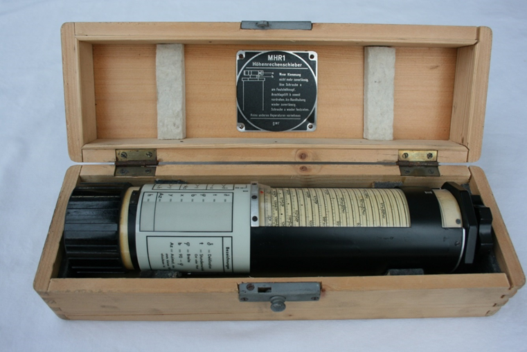
Figure 3 Dennert and Pape MHR1 fully collapsed for storage and transport
A considerably larger, and thereby likely more accurate, variant was the HR2. It is believed that this unit was meant to be bolted to a table so likely was a naval instrument.
Dennert and Pape production records show the MHR1s were made thru the waning days of WW-II and many were likely never issued. After the war, a number of units were manufactured under the Aristo brand until about 1958 and may have been sold until the 1970s from remaining stock on hand. Compared to Bygrave slide rules, a larger number of HR1/MHR1 units still exist but they are still quite rare. One recently came up for auction and sold for more than US$1700.
Bill Morris’ 2010 reproduction was of an MHR1, so I’ll mention a few specifics about the historical MHR1.

Figure 4 MHR1 showing full extent of scales
The inner tube is 5.4cm in diameter and approximately 23cm long and carries a log-cotangent scale in a helix. The scale length is 758.4cm over 45 turns and a pitch of 0.45cm. The scale runs from 0⁰20’ to 89⁰40’ and then back from 90⁰20’ to 179⁰40’. Because of the nature of cotangents, the scale is condensed near 45⁰ but the marks become further and further apart near the extremes.
The middle tube is 5.8cm in diameter and 22.5cm in length and carries a log-cosine scale in a helix. The scale length is 407.3cm over 22 turns and a pitch of 0.45cm. The scale runs from 0⁰ to 89⁰40’ and then back from 90⁰20’ to 180⁰. Because of the nature of cosines, the scale is condensed near 0⁰ but the marks become further and further apart as we near 90⁰.
The tube is 6.2cm in diameter and 22.2cm in length. It holds two Perspex windows with red index pointers to align the two scales.
Instructions are printed on the outer tube along with a scratch pad for pencil scribbling by the user.
Bill’s reproduction is almost identical in dimensions and other outward details including the Perspex windows with red index pointers, and end caps. I am unaware of the details regarding the locking mechanism, but Bill’s reproduction does have a working locking mechanism which I find very handy. (Rotating the locking knob causes a close-fitting O ring to be squeezed by a circular plate. This increases its diameter slightly so that friction can be increased to the point of locking.) Purists may note that a “real” MHR1 locks the cylinders by turning the knob counter-clockwise, whereas the reproduction locks by turning clockwise, a detail which takes nothing away from the reproduction.
And, it should be added, no one seems to have yet found the courage to take an actual MHR1 apart to inspect the details of the locking mechanism internals. (The original appeared to pull a cone into a split tube to open it out.)
Unlike the originals, which used aluminum tubes, this instrument uses laminated pressed paper tubes with the scales printed on paper and then glued to the tubes. I understand Bill sourced the tubes from Wolfgang Hasper, a member of the NavList discussion board and the tubes appear to still be available for about 40 Euros despite the passage of a number of years (See References at end of this post).
The cotangent scale runs 1⁰30’ to 88⁰30’ and then back from 91⁰30’ to 178⁰30’ while the cosine scale runs from 0⁰ to 89⁰30’ and then back down from 90⁰30’ to 180⁰. This is slightly different than the original scales but the areas where they differ are only in the expanded region of cotangent and cosine where adding the additional scale length provides very little added range while increasing the length of the helix by a non-linear amount. As mentioned below, the scales were generated by some very smart people at NavList and this may well be an optimization over the original scales.
The instrument has a bit of heft to it (I lack a proper scale but it feels to be around half a kilogram) and has a solid feel. However, as the tubes are not metal, I take care with it so as not to drop it.
I’m not sure where Bill found the images for the original German language instructions but they are also faithfully reproduced on the outer cylinder. (I think I may have simply copied them using a near-identical typeface.)
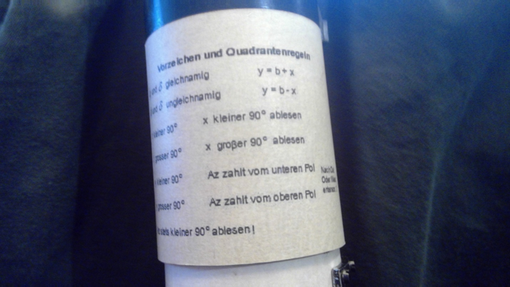
Figure 5 Instructions

Figure 6 More instructions, scribble pad, and stop
The outer cylinder is also made of laminated pressed paper and the upper part is painted black to match the historical instruments. Two windows are cut out to show the scales. Attached to each window is a piece of Perspex molded to fit the different diameters of the two scale cylinders. Each Perspex piece has a red index mark. Visually, this is very similar to a historical MHR1.
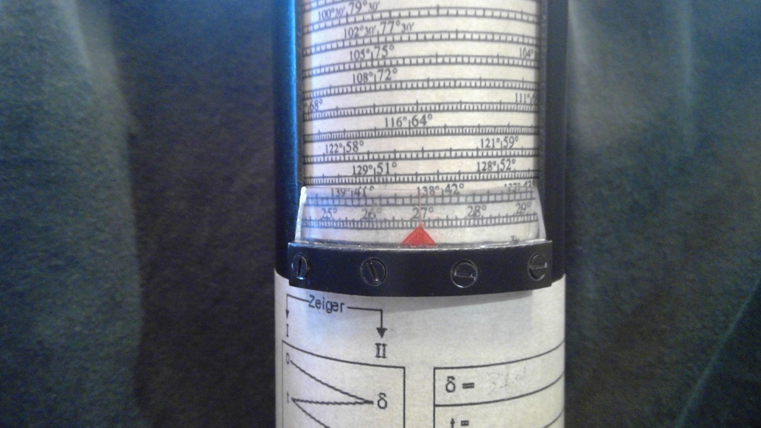
Figure 7 Cosine scale index
The lower end cap appears to be plastic – I do not know how he made this piece but it appears to follow the form of the original very closely. (I think I used a scrap of the cursor tube and milled grooves in it.)
The upper end cap and tightening knob are turned and milled from aluminum stock. Bill says that the knob is a bit smaller than the historical instruments but I find no loss in functionality because of it.

Figure 8 Cotangent scale index, upper endcap, and locking knob
Bill got the scales from the clever and skilled people on NavList as PDFs which are easily printed at home. I believe the scales taken from NavList were scaled to fit the outer diameters of the MHR1 cylinders exactly – attempting to fit the scales to tubes of different diameters would necessitate a bit of experimentation with the printer magnification settings.
Care must be taken to align the scales on the tubes so that the edges butt against each other without gap and without overlap. Bill did an outstanding job, of course, putting the scales on. He then added a bit of shellac (French polish) to protect the scales. He tells me, “Purists say that French polish is a process, not a substance.”
The tubes rotate with just enough friction to make the scales easy to adjust both in rotation and in length. They will stay put without the locking mechanism being set and the outer tube mostly protects the middle tube from unintended inputs when manipulating the inner tube.
I feel that Bill has created a very fine instrument faithful to the lines and function of the original Dennert and Pape MHR1s.
So, how well does it work?
I shall present the answer to the question in two parts by answering two more directed questions. First, how easy it is to manipulate? Second, how accurate are the results taken from it?
I have never held an actual Bygrave or MHR1, so I cannot speak for those instruments. However, I cannot imagine they would be significantly different to manipulate than the reproduction.
The manipulations are relatively straightforward, but some practice is required before competency is attained. As mentioned above, the scales for log-cotangent are very compressed around 45⁰ and become widely spaced around 0⁰ and 90⁰ – and likewise for the log-cosine scale being compressed near 0⁰ and more widely spaced around 90⁰. For those of us with aged eyes, a pair of reading glasses and good lighting will be helpful to read the scales. The excellent index line that Bill constructed helps greatly in the alignment department.
Bygrave’s original patent stated that the inner cylinder carried a log-tangent scale, but it is believed that this was switched to a log-cotangent scale for production instruments because it allowed the scales to advance in the same rotational direction. This is a great help in practice when the scales become widely separated as it is quite easy to misread the value on the scale. For example, is this 87⁰5’ or 87⁰55’?
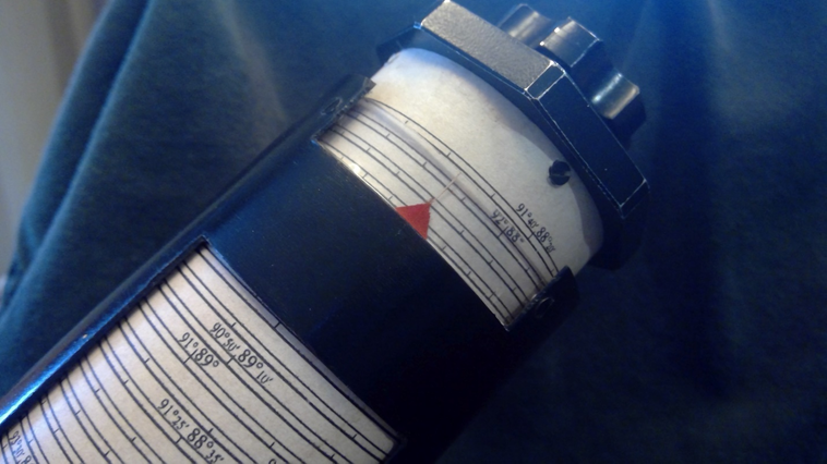
Figure 9 Labels are far apart at the extremes
Since both scales advance to the right, a potential source of errors is eliminated.
That said, it is still easy to mis-read the scales, especially when aligning from one scale to another – trying to read an unlabeled mark on the cotangent scale while aligning to another unlabeled mark on the cosine scale does require a bit of back-and-forth twisting. I dare not put a pencil mark on the paper/shellac reproduction, but I have a sneaking suspicion that is precisely what navigators did on historical instruments.
Locking the two scale-carrying cylinders together is quite easy. Historical Bygraves did not have this feature and a worn-out instrument could have sufficiently reduced friction to allow them to slip relative to each other which would result in errors. Care must be taken to align the index pointers carefully before locking them, however, as the two cylinders will be rotated and slid along the central axis – by carefully aligning the scales at the start, the index pointers will be aligned to the correct part of the helical scale after sliding them to the next step in the process rather than being ambiguously in between.
The reproduction is still quite pristine so there is a reasonable amount of friction between the cylinders from a liner layer of baize between the tubes so a locking mechanism isn’t important, yet.
Now, we tackle using it.
One of the nice things about the Bygrave is that one is able to find Hc and Zn from a Dead Reckoning (DR) position which can have non-integer LHA, latitude, and longitude. This is in contrast to typical HO229 and HO249 reductions where one uses an assumed position to get integer LHA and latitude. In theory this saves a plotting step since the navigator can plot directly from the DR position. Of course, it would still be possible to work the fix using an assumed position different from the DR position that would provide integer inputs – an advantage with using integer inputs would be that the scales would be easier to read as you could move the pointers to the integer values on the scales for some, but not all, of the steps.
To make it more interesting I will show an example using an “interesting” DR position as the input to the computation, which was, incidentally, my first try with the instrument. Here are the parameters:
- May 19, 2021 – 01:52:00 UTC
- Object: Spica
- DR position: 34⁰1’N, 77⁰2’W
From the Nautical Almanac:
- GHA-Aries: 251⁰55.5’
- GHA-ms increment: 13⁰2.1’
- SHA-Spica: 158⁰25.2’
- Computed GHA-Spica: 63⁰22.8’
- Declination Spica: S 11⁰16.4’
In the Western Hemisphere, I subtract the DR longitude from GHA-Spica to get LHA-Spica: 346⁰20.8’.
Now we have the information that allows us to enter into a special worksheet. This worksheet is from Gary LaPook’s “flat Bygrave” work and is applicable here.
We must first calculate “H” which is a function of LHA – since LHA is greater than 270 and less than 360, we enter LHA into the corresponding column and, as instructed by the form, subtract it from 360⁰ to get H of 13⁰39.2’. Because DR latitude and declination are contrary name we circle “-W” – then enter these values onto the worksheet along with a “-“ on the W line and the declination in D.

Figure 10 Initial pre-computation
Now we pick up the Höhenrechenschieber and begin to follow the zig-zag instructions on the worksheet or those on the side of the instrument. The first zig-zag solves for W, the second for Az, and the last for Hc.

Figure 11 The three manipulations we will do on the instrument
Set 0 under the index line on the cosine scale:

Figure 12 Set 0 on the cosine scale
Then, while ensuring that the index remains on 0 on the cosine scale, set declination on the index line on the cotangent scale:
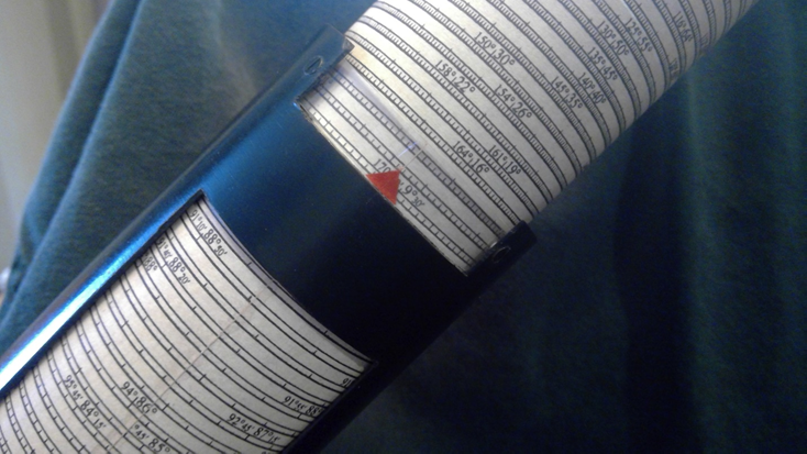
Figure 13 Set 11-16.4 on the cotangent scale – note scale expansion so care must be taken to set the pointer
Now we lock the tubes to they do not shift relative to each other. Then shift the cosine scale so that H is under the index line:
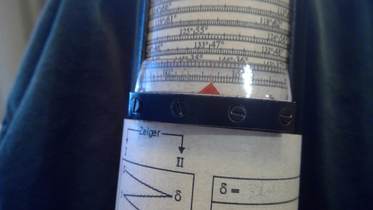
Figure 14 As close to 13-39.2 as I can photograph
Now read W from under the index line on the cotangent scale:
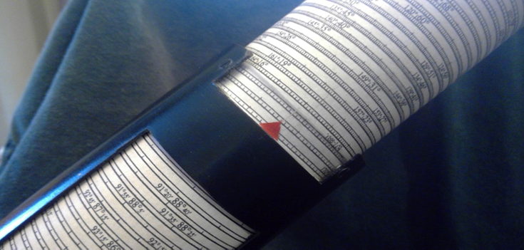
Figure 15 Trust me, that says 11-36
We write the extracted value of W (11⁰36’) on the form reserved for it – remember in this example, we previously wrote “-“ on the line so W is negative. Enter the DR latitude and compute the “co-latitude” as 90⁰ – DR latitude:

Figure 16 Enter W read from cotangent scale, enter latitude and calculate co-latitude
Summing the resulting co-latitude with W, we compute X. As X is < 90, we set Y equal to X.

Figure 17
Now, with W, H, and Y computed, we can pick up the instrument again. First, we unlock the scales from the previous step, then we set W on the cosine scale:

Figure 18 W = 11-36
Then set H on the cotangent scale:
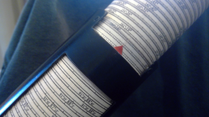
Figure 19 Set H=13-39.2 (the “16” to the right is showing “166” (the angle complement of 14), not “16”
Then lock the cylinders together, then slide the scales so that Y is on the index on the cosine scale:

Figure 20 Rotate to set Y = 44-23
And finally we read Az from the index on the cotangent scale.
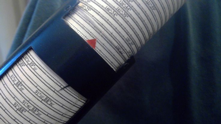
Figure 21 Read Az as 18-24.5
Then enter Az on the worksheet space.
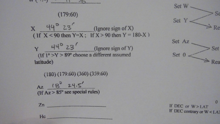
Figure 22 Insert the Az read from the cotangent scale onto the worksheet
The worksheet lists rules for computed Zn for North and South Latitudes, LHA, and DEC/W vs. DR latitude.

Figure 23 Rules for computing Zn from Az – LHA = 346deg 20.8′, Contrary name
In this case, declination and DR latitude are contrary name and LHA is between 180 and 360 so we use Zn = 180 – Az and enter it onto the worksheet.

One more step on the device is required to extract Hc. We start by unlocking the scales, then setting Az on the cosine scale:
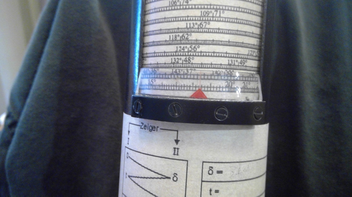
Figure 24 Set Az on cosine scale
Then setting Y on the cotangent scale and re-locking the scales:

Figure 25 Set Y on cotangent scale
Then we rotate the cosine scale to set 0 on the index:

Figure 26
And we then read Hc from under the index line of the cotangent scale:
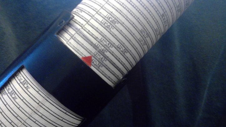
Figure 27 Done!
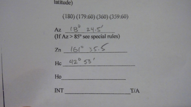
Figure 28 Extract Hc from the cotangent scale and enter it on the worksheet
For this exercise we ignore the worksheet entries for Ho and INT – these are the standard sextant observed altitude and the intercept distance (Zn-aligned To/Away) from the DR position, which is in common to standard methods of plotting lines of position.
I have programmed a spreadsheet with the equations to compute Hc and Zn directly from the trigonometric formulas. This spreadsheet takes the same inputs as the MHR1 – namely, DR latitude and longitude, declination of the object, and LHA of the object. The results for both the MHR1 computations and the spreadsheet are:
| MHR1 | Spreadsheet | |
| Hc | 161⁰ 35.5’ | 161⁰ 36.0’ |
| Zn | 42⁰ 53.0’ | 42⁰ 53.1’ |
I’d say this is a pretty good result and certainly not bad for a first try! Bill’s excellent workmanship made the manipulations easy and at no point did I have to expend very much of my limited brain power on fighting the instrument.
I must admit that this wasn’t my “first try” with a Bygrave-like approach. As part of my research, I found LaPook’s “flat Bygrave” and so printed the scales onto paper and transparency to make one. While not to say that the “flat Bygrave” cannot be just as accurate, I could not get the same level of accuracy as with Bill’s excellent reproduction. The relatively small size of the flat scales and the lack of color saturation of my ink-jet printer conspired to make my printed “flat Bygrave” very difficult to read, but it does have one advantage over the cylindrical instruments in that you cannot get lost on the scales since you can easily see the degree marks on either side of the “index.”
I managed a 3-star series using only my sextant, the MHR1, and the Nautical Almanac and came up with a plot that was quite good.

Figure 29 Look, Ma! No HO229!
Sadly, there will never be a market for a mass-produced Position Line Slide Rule. Time and technology have moved past. As it was, it took me all of 5 minutes to program a spreadsheet to solve for Hc and Zn, and then milliseconds for the computer to spit the answers out after I enter the last parameter. However, there is no sense of accomplishment from tapping at a keyboard – unlike twisting, turning, sliding, scribbling, and sweating to get the required answers. And, maybe for a moment, I am a young navigator on a trans-Atlantic crossing standing under an astrodome and swaying sextant trying to guide my aircraft and crew to a safe landing on the other side.
Thank you, Bill, for entrusting his beautiful instrument to me and letting me play with it. Your kindness is greatly appreciated.
Arthur Leung
North Carolina, USA
REFERENCES:
A better history than mine of the position line slide rules can be found here in Ronald W.M. van Riet’s excellent paper, a link to which is here:
PositionLineSlideRules.pdf (rechenschieber.org)
A Bygrave manual may be found here as part of a post by Gary LaPook:
NavList: Bygrave slide rule (106329) (fer3.com)
Gary LaPook’s writeup on using the Flat Bygrave and PDF of his workform, both pertinent to working a “not-flat” MHR1, can be found here:
NavList: New compact backup CELNAV system (changed for archive) (107414) (fer3.com)
Modern Bygrave Slide Rule – Fredienoonan (google.com)
Virtual Bygrave emulators also exist:
SlideRule (friendsofthevigilance.org.uk) – historical Bygrave emulator
SlideRule (friendsofthevigilance.org.uk) – flat Bygrave emulator
For those wishing to try the “Flat Bygrave” or build a cylindrical Bygrave, PDFs of the scales may be found here in posts by Robin Stuart:
NavList: Flat Bygrave alternative configuration (127166) (fer3.com)
NavList: Postscript code for making Bygrave Scales (127398) (fer3.com)
The two scales must be printed separately but care needs to be taken so that the magnification is correct so the scales will align properly between the two cylinders.
Wolfgang Hasper had additional tubes, as of 2019, for those wishing to make their own:
NavList: Re: Buy or build a modern Bygrave slide rule (146016) (fer3.com)

You must be logged in to post a comment.