Shackmans
The firm of manufacturing jewellers, David Shackman and Sons, is well known to collectors of fine watches. Following the First World War, the British government banned the importation of gold articles, including watch cases, so firms like Shackmans made the cases for imported watch movements by Longines and other famous Swiss watch-making firms. For many years, their initials “DS&S” were to be found on the cases of high-class gold watches. Making watch cases involves some precision machining and as the Second World War progressed, Shackmans converted to war work. In July, 1942, Albert and Reuben Shackman filed a patent application (9168/42) for “Improvements in or relating to Sextants” and the full specification was accepted in September 1943 (556,034).
Patent claims
The claims made for originality seem on the whole to be spurious, as other manufacturers including Hughes and Son and Heath and Co. had anticipated some of them. The micrometer screw in its bearings was mounted between “adjustable pointed bearing screws” and held in engagement with the rack by means of a leaf spring (my Figures 1 and 2); and the bearing of the micrometer worm that received thrust from a pre-load spring was conical (my Figure 3) a by-no-means unusual feature of plain bearings that also have to accommodate thrust. Perhaps the main difference from other manufacturers was that the diameter of the worm was large, about the same as that of the micrometer drum, and the worm had parallel sides (my Figure 3). The pointed screws are labelled “11” in Shackmans’ Fig 4, the spring “12” in their Fig 1, the worm is “4” in their Figs 4 and 5, and the conical bearing surface is labelled “20” in their Fig 5.

Figure 1: Spring-loaded worm engagement
-

Figure 2 : Mounting between centres.
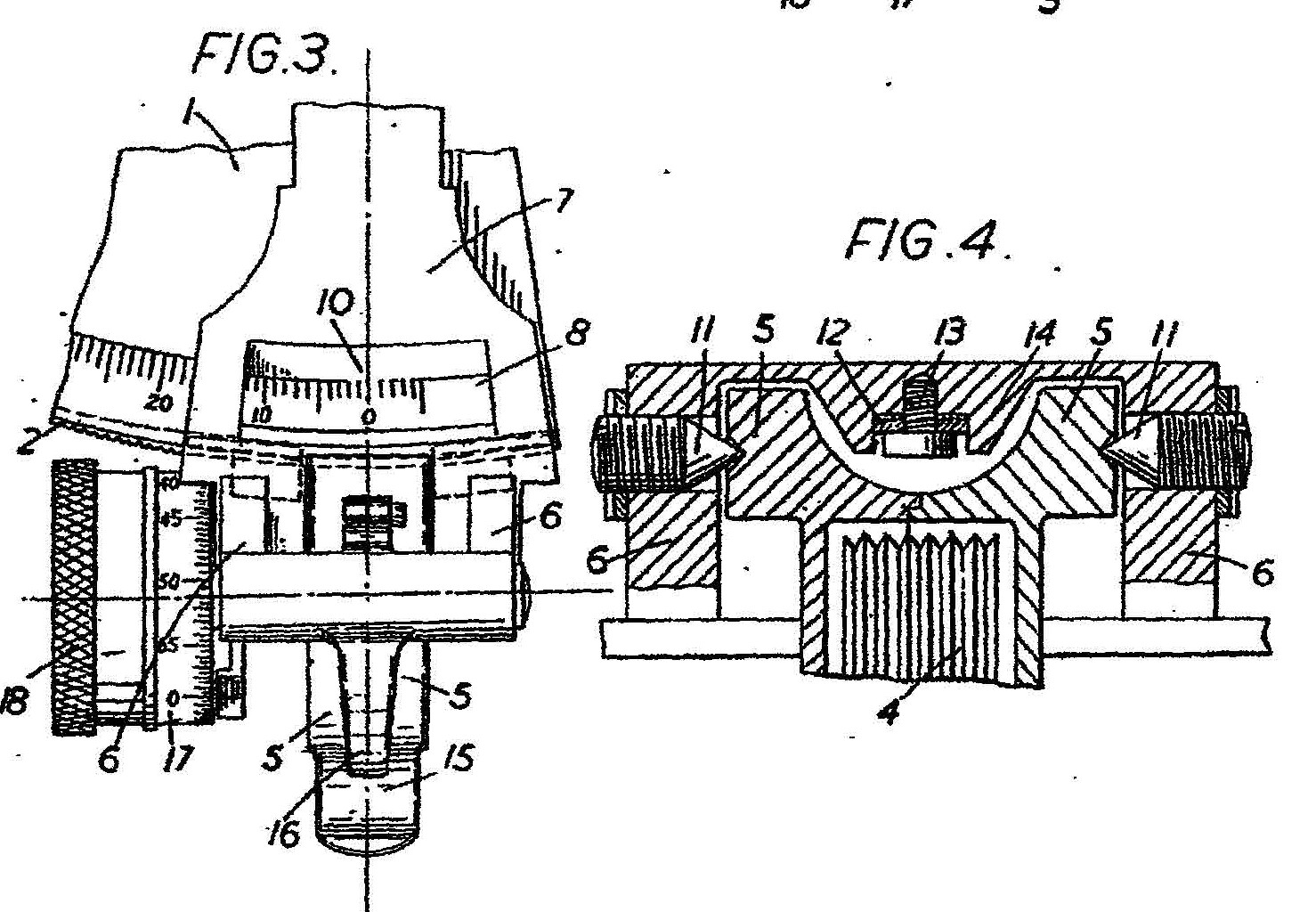

Figure 3: Large cylindrical worm
Most micrometer worms are conical so that the axis of its shaft is not tangential to the rack, allowing a relatively large micrometer drum to be used without it fouling the rack. Shackman’s claim says “With such an arrangement due to this angular positioning of the worm spindle, it is not possible to obtain correct interengagment between the teeth on the worm spindle and the teeth on the arc, and this incorrect interengagement of the teeth resulted in excessive wear and prevented accurate readings being obtained, particularly after the instrument had been in use for some little time.” Here Shackmans were being a little disingenuous. Most worms have an included angle of taper of about 15 degrees, so that the thread angle does indeed get larger towards the smaller end of the worm. However, provided that at least part of the worm engages correctly with the rack, this will have no effect on the accuracy of the instrument, which resides principally in the rack. Periodic errors in the worm will result in errors of the micrometer reading during the course of a full rotation, but these errors are just as likely to arise in a cylindrical worm as in a tapered one.
The Ramsden connection
At the beginning of the 20th century, a Mr W T Parsons owned a Ramsden-type dividing engine and, through a series of sales, it came into the hands of a Mr A J Bennett, probably the father of G J Bennett, who was the Managing Director of Shackmans in the 1990’s. A J Bennett sold three dividing engines to the Science Museum in London and in June 1942 asked for the loan of one of them back for war work. The Museum was told in 1945 by R C Shackman that it had been used to graduate “upwards of 2000 sextants”. After several requests from the Museum, it was finally returned in 1951. Since the sextants made by Shackmans were micrometer sextants, it is perhaps most likely that the machine was used for engraving the arcs, the degree markings of which need no special precision, but it is also possible that it was used in some way as an improvised hobbing machine to form the racks. My sextant has a serial number in the 2200’s and I have seen one with a serial number over 3900, so it possible that 4000 or more were made, though there is of course nothing to say that the serial numbers began at 0001. Mine was made for Kelvin and Wilfred O White of New York and Boston in late 1943 and sold in Seattle in 1956 for $85 (Figure 4), while the more recent sextant appears to have been marketed by Hughes and Son.

Figure 4: Anonymised sales document.
The sextant came to me in a rather battered, but essentially sound, solid wooden case, possibly of walnut, having brass fittings and corner dovetails (Figure 5) and Figure 6 shows a general view of the instrument as received. Some rust is visible, betraying the use of steel screws as a war time measure and, except for the shearing off of one of these rusted screws, overhaul and repainting was straightforward. I will not give an account of this, but instead concentrate on structural features of interest (to me, if not the reader!). The sextant frame is of the popular and very rigid three-circle pattern and is a bronze casting. Figures 7 onwards are of the restored instrument.

Figure 5: Case as received.

Figure 6: Sextant as received
Index arm
While the shades and mirror brackets are typical of British sextants of the time, the index arm is of interest, as it illustrates how a part that would have made the sextant uncompetitive in price in peace time can be tolerated in times of war. At the upper end (Figures 7 and 8) it is just wide enough to accommodate the mirror and allow attachment of the journal of the bearing. There is no intermediate disc as in practically all other sextants of the period. It appears that there has been an effort made to save every scrap of non-ferrous metal, until one sees that the underside is heavily ribbed and the lower end of the index arm, instead of being a continuation of a flat strip of metal, is in fact a casting of considerable complexity (Figure 9). Rather than having been stamped out of brass sheet, the whole index arm is a bronze, probably gunmetal, casting.

Figure 7: Upper index arm and mirror
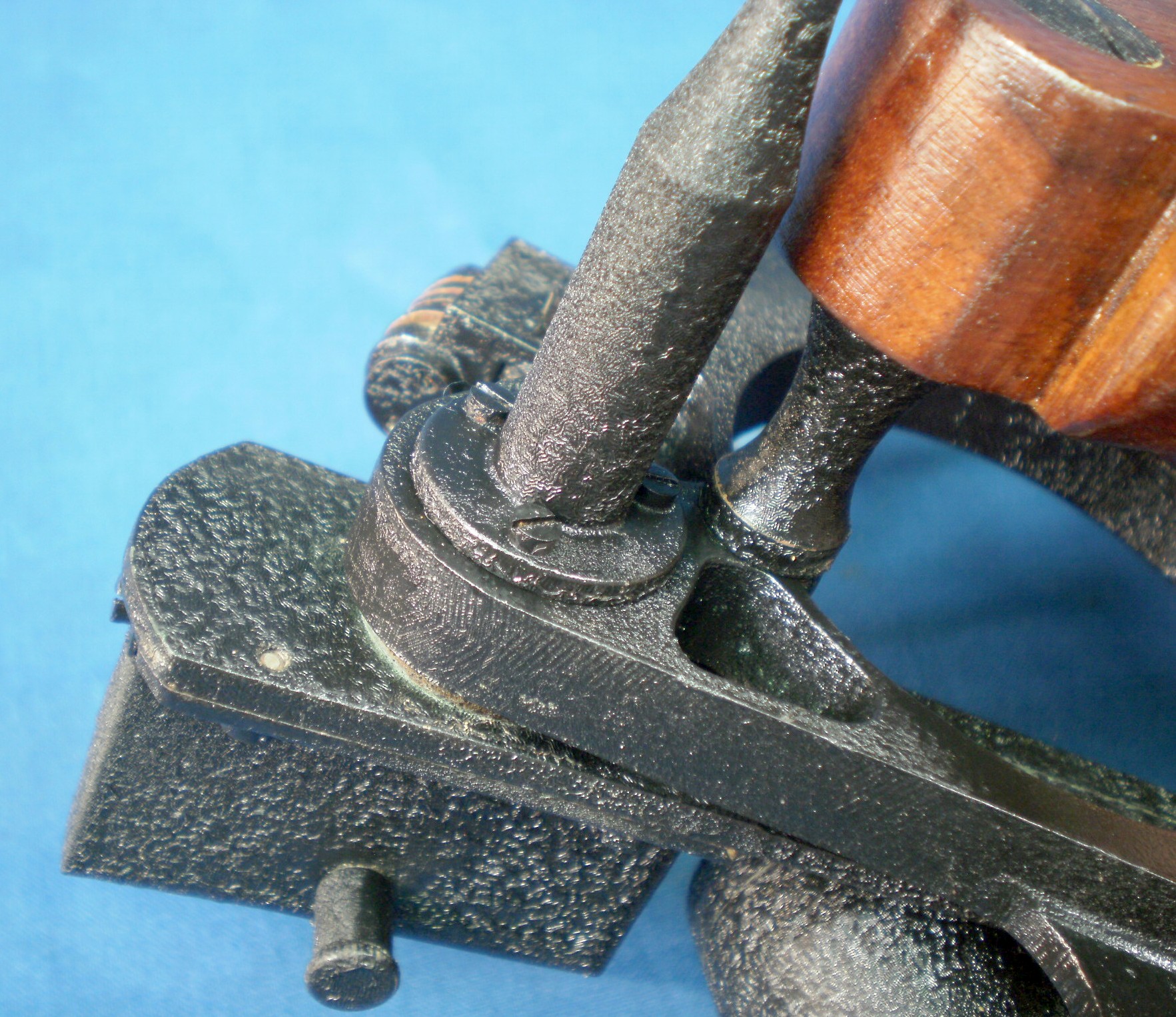
Figure 8: Underside of upper index arm
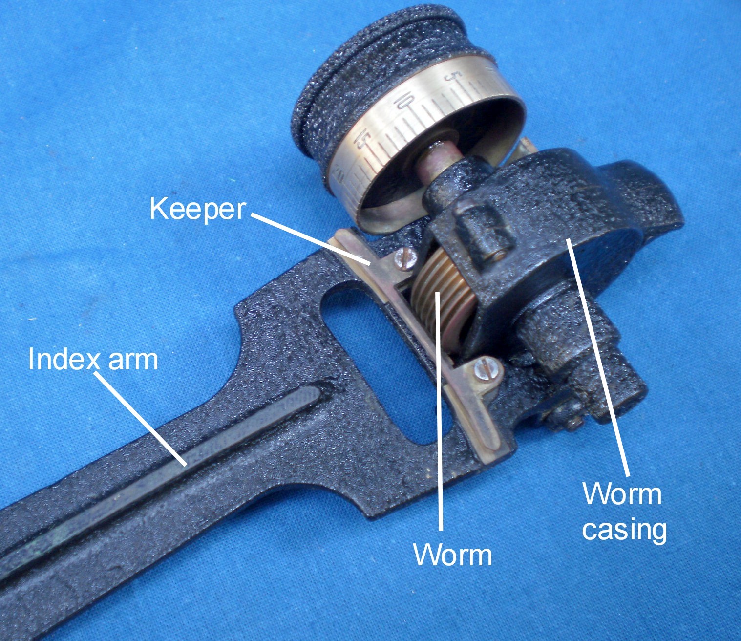
Figure 9: Underside of lower index arm
The central rib adds stiffness against flexion to the index arm, a feature ignored as unnecessary by many makers, and the complexity of the lower end is necessary so that the micrometer assembly can be mounted between centres. We can note in passing that the keeper, which prevents the index arm from lifting off the limb and maintains the worm in alignment with the rack, is itself a piece of some little complexity, rather than being the simple shouldered screws used by many makers.
Micrometer assembly
Figure 10 gives a general view of the micrometer assembly from the front. It shows one of the centre locknuts and screws about which the worm casing rotates to bring the worm into engagement with the rack, impelled by a leaf spring. The screws are carried in a forward extension of the index arm which is braced by a transverse bar that forms part of the casting, together with an extension over the leaf spring
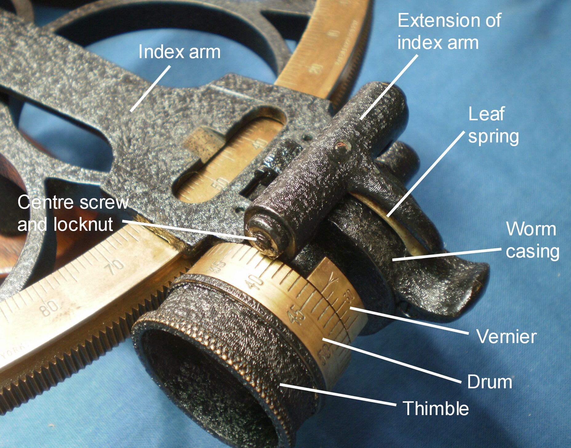
Figure 10: General view of micrometer mechanism
Figure 11 shows a partially exploded view of the mechanism. The casing is seen to be made in two halves held together by three screws. The drum is held on to the worm shaft by the threaded thimble, so that when the thimble is slacked off, the drum can be rotated to bring its reading to zero when the main index on the index arm is opposite a whole number of degrees. Once adjusted, the thimble is locked in place with a slotted lock nut. The cylindrical end of the worm casing contains two ball bearings separated by a spring. This provides axial preload to the worm shaft so that there is no end play of the shaft. In the patent drawing there are two conical parts (23 and 24 in my Figure 3) and the amount of axial thrust is shown as adjustable by threaded part 25. No doubt this was found to be an extra and unneccesary complication.
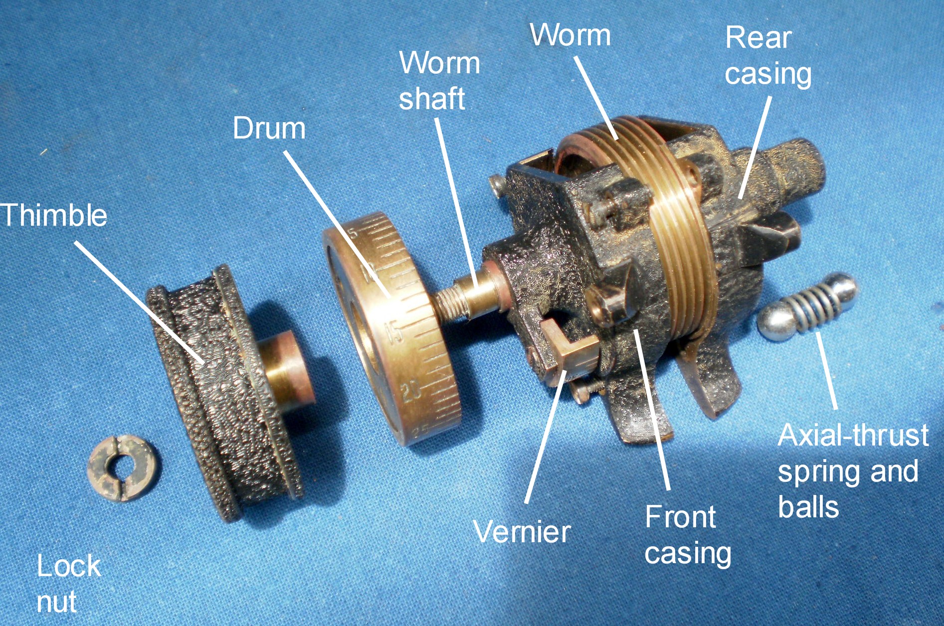
Figure 11: Micrometer mechanism partly exploded.
Figure 12 shows the mechanism fully exploded. The casing is made of two complex little castings, one with a lip that fits accurately inside a recess in the other to ensure concentricity. One of the bosses for the pointed centre screws is shown at top right of the right half-casing. The casing halves are machined all over inside and the conical seat for the thrust face of the worm shaft is shown on the left half-casing. These small parts, while no doubt child’s play to watch case-makers, must nevertheless have been difficult to hold for machining and have added significantly to the cost of the micrometer mechanism. Compare it with the elegant simplicty of the mechanism shown in Figure 3 of my post on the US Maritime Commission sextant by Leupold and Stevens, which is based on Hughes and Son’s design. The large diameter of the worm is a mixed blessing, as there is a large area of worm in contact with the rack and when rotating the worm there is a marked tendency to stick-slip, sometimes known as “stiction”.

Figure 12: Micrometer mechanism fully exploded
Index arm bearing (Figure 13)
The bearing has a protective cover that doubles as a leg, seen in Figure 8, above. The bearing itself is a slender shell of brass with a boss that fits closely into the frame and which is secured to the frame by three screws from the front. The journal, the part that rotates within the bearing, is of hard bronze. The washer and journals have flats that prevent the washer from rotating, so that the screw which secures the washer and journal in place can be nicely adjusted to remove all shake without there being any tendency for rotation of the journal to alter the setting of the screw. Note that the flat of the washer has been silver soldered into place, a quite usual process for a jeweller, while an engineering approach would probably have used a broach, a shaped cutting tool that is forced into a hole to produce shaped holes.
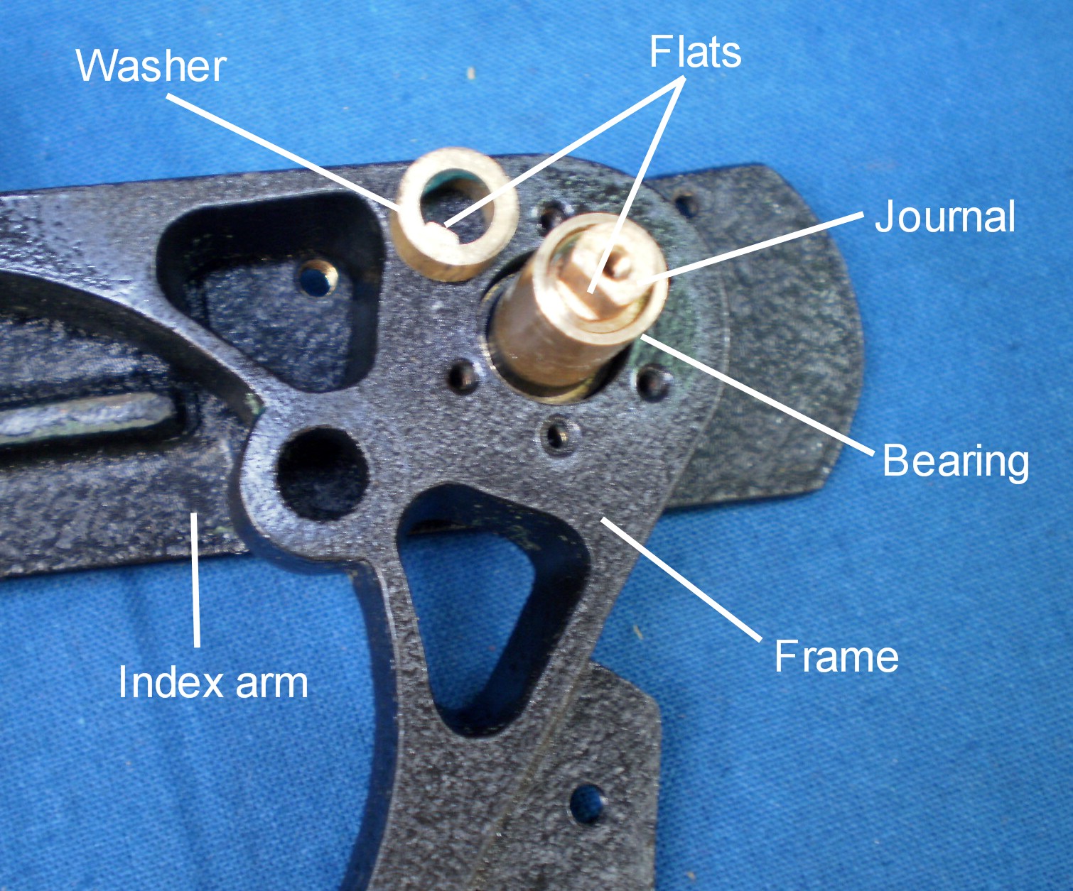
Figure 13: Index arm bearing.
Shades mounting
When rotating the shades in position, it is a nuisance if more than the selected shade moves, so most makers, Shackmans included, separated the shades by washers that could move along the shaft but not rotate upon it, usually by machining a key way on the shaft, with internal tongues on the washers fitting into the keyway. The amount of resistance to rotation could be adjusted by means of a screw on the end of the shaft, so it was obviously necessary to prevent the shaft itself from rotating in the bracket while the adjusting screw is turned. Most makers simply passed a taper pin through the bracket and shaft. Shackmans used a more complicated approach (Figure 14) that again involved unecessary machining operations. They tapped holes through the boss on the end of the shaft and into the bracket for two small locking screws that prevented both axial movement and rotation, just like a taper pin, but with more complexity.

Figure 14: Shades assembly
Telescope
The telescope is a three power Galilean “star” ‘scope with an objective lens of 25 mm diameter. It screws into a ring atop a column that is attached to the frame by a single large screw and prevented from rotating by a dowel pin. There is no provision for rise and fall or collimation, nor was any necessary for the type of observation likely to be made with the instrument.
Case details
The sextant is located in the case by a simple wooden pocket, shown broken in Figure 6. A wooden latch over the handle and two cork faced pads in the lid hold it securely in place when the lid is closed. The ends of the legs sit on the heads of drawing pins (thumb tacks) so that the rounded ends of the legs do not work themselves into the floor of the box. The sextant can be placed in the case with the shades in any position and the index arm in any position between -5 and 110 degrees, practical features not appreciated by all makers. Figure 15 shows the re-finished case.

Figure 15: Re-finished case.
The handle is a drawer pull. The latches are safety latches (Figure 16). It is neccessary to push on a springy leaf of brass before the latch can be swung out of the way. There is a box lock, a pocket for an eyepiece shade and a staple in the side of the box to hold the adjusting pick.

Figure 16: Safety latch.

You must be logged in to post a comment.