Previous posts in this category include: “An Old Wooden Quadrant Restored”, ” A turn-of-the-century French sextant”, “A Half-size Sextant by Lefebvre-Poulin”, ” A Fine Sextant by Spencer, Browning and Co”, “A C19 Sextant Restoration” , “Making a Keystone Sextant Case” , “Restoring a C. Plath Drei Kreis Sextant” , “Heath Curve-bar sextant compared with Plath” , “A Drowned Husun Three Circle Sextant”, ”Troughton and Simms Surveying Sextant” , “A Sextant 210 Years On” , “A fine sextant by Filotecnica Salmoiraghi”, “A British Admiralty Vernier Sextant”, “An Hungarian Sextant via Bulgaria” , “A Half-size Sextant by Hughes and Son” and “A Fine C Plath Vernier Sextant”, “Heath and Co’s Best Vernier Sextant.” and “An Early C19 Ebony Quadrant Restored”.
A few months ago I acquired an old sextant for a very modest price, as it was without telescopes or case. Restoration was straight forward, as all the parts were present. It was only necessary to clean and re-lacquer parts and polish screw heads and then find a new home for the instrument. Figures 1 and 2 show the general arrangement of the restored sextant from the front and back, and I have labelled the main parts for those who have not yet had the wisdom to buy “The Nautical Sextant”.

Figure 1: The sextant and its parts.
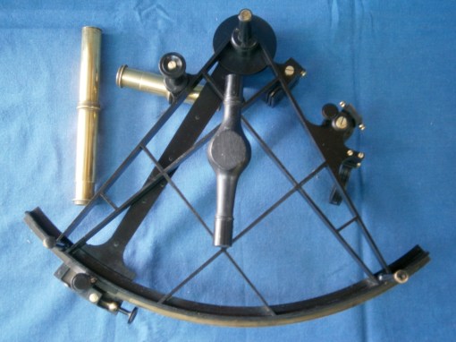
Figure 2: Rear view of sextant.
I show the naked frame in Figure 3. It is slender by modern standards, but seems to be rigid enough for its purpose.
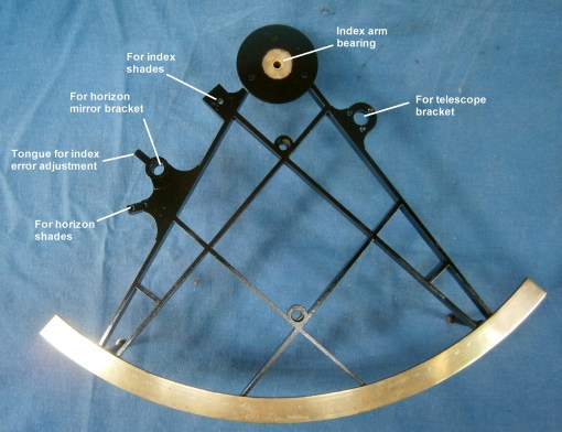
Figure 3: The naked frame restored.
I believe that this is a relatively early sextant, based not only on the name engraved on the limb but on several other factors. To take the name first, it is “J Watkins Charing Cross London”. This must refer to Jeremiah Watkins who succeeded his uncle, Francis Watkins (1758 – 1810) in 1784 at the age of about 26 years. I have been able to find only one other sextant with J Watkins’ name on it (sold in London in 2014) and I suspect that he was the retailer rather than the maker. It was common practice for sextants, chronometers, clocks and the like to be sold un-named, for the retailer to add his name. The main activity of Watkins senior and junior, and later Watkins and Hill, was in making telescopes with achromatic lenses.

Figure 4: The name.
Looking closely at the name (Figure 4a ), the second “s” in “Charing Cross” is the old English long s, with a nub on the left of the descender. This form of s had fallen into disuse in printing by 1800 and its use here suggests the engraver had trained well before 1800.

Figure 4a.
The brass limb was attached to the hard bronze frame by countersunk screws whose heads were then filed off flush, and the ghost of one of these screw heads can be seen above the “n” of Charing Cross. Rather unusually, the divisions are made directly into the brass rather than into a band of silver let into the brass, a practice established well before 1800. The usual explanation for this practice is that brass of the time contained hard spots which could have diverted the scriber of the dividing engine from its true path and that lines on brass tended to be ragged. However, this may have applied only to English brass, as makers preferred if they could to import high quality “Dutch” brass from near Aachen in Germany.
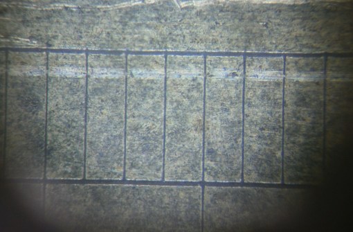
Figure 5: Magnified view of scale divisions.
A close up view of the divisions (Figure 5) shows them to be perfectly regular, so that the scale was, I am sure, machine divided. Jesse Ramsden’s first dividing engine was finished in about 1766 . It surpassed all previous attempts at accurate machine division, but he was not satisfied with it, and completed an improved version in June 1774. Around about this time he produced a sextant shown in Figure 6, with a frame very similar, if not identical to my Watkins’. By 1789 there were three dividing engines in London, By Jesse Ramsden, John Troughton and John Stancliffe, and by 1808 there were perhaps a dozen.
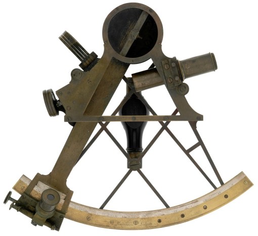
Figure 6: Sextant by Jesse Ramsden.
This suggests to me that the two sextant frames had a common source in a specialist foundry and we know that Ramsden used specialist founders when he needed castings. The finish is very regular and there is no signs that it was sand cast. More likely is that it was cast in bell metal (a bronze high in tin) by the lost wax method.
The radius of the arc is nine inches (229 mm) and by 1800, because it had by then become possible to divide small radii more accurately, the more usual radius was around six and a half inches (165 mm). Thus, these several features lead me to suppose that the sextant was made some time after 1774 and before 1800.
The telescope ring and rising piece are of a form that remained common well into the twentieth century. The telescope is held in a ring that can be adjusted so that the axis of the telescope is parallel to the frame, while the whole can be raised or lowered on its square rising piece by means of an internal captive screw and knurled knob (Figure 7).
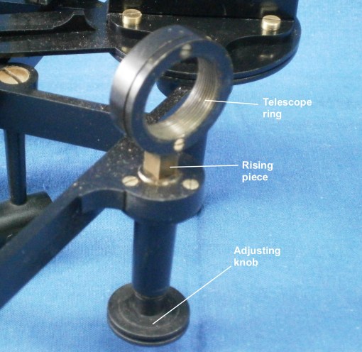
Figure 7: Telescope ring.
Compared to later sextants the index mirror is unusual in that there is no provision made for adjusting it to be at right angles to the plane of the arc. In some sextants of this era, of the three large screws seen in Figure 8, only the two outer ones attached the bracket to the index arm, while the central screw was threaded into the bracket and its tip bore on the face of the index arm, so that it was possible to rock the bracket a little to adjust it. In this sextant, the bracket was simply made square in the first place.
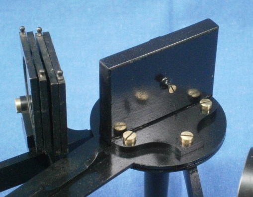
Figure 8: Index mirror bracket.
Figure 9 shows the front of the bracket and two of the three nubs or nipples on its face, against which the mirror was held by a clip with three tongues opposite the nubs. When the small central screw seen in Figure 8 is tightened, the mirror is held strain-free to the bracket by the clip.
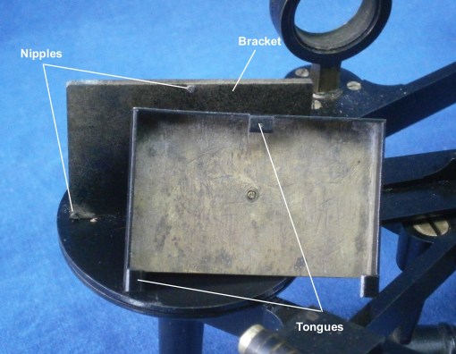
Figure 9: Index mirror clip and bracket.
The index arm bearing is shown in Figure 10. It is of the form used by almost every maker until late in the twentieth century. The index mirror is attached to a disc to the underside of which is attached a tapered journal which runs in a corresponding hole in the index arm bearing. The fit is adjusted by means of an axial screw via a washer. The washer has a square hole in it that fits over a square on the end of the journal. This prevents turning forces from being applied to the screw and loosening or tightening it.
In this sextant, the whole is enclosed in a cover, which also doubles as one of the feet of the instrument. Many makers copied this practice, though in the twentieth century, when two World Wars required quantity production, it was often omitted.

Figure 10: Index arm bearing.
The method of adjusting the position of the index arm is shown in Figure 11 and is typical of the practice used in practically all vernier sextants until the last were produced in the late 1930s. A block is able to slide in a guide fabricated on the rear of the index arm expansion and the block carries a bronze nut, which sometimes has an adjustable split in it to ensure a close fit upon the tangent screw. Running in the nut is the steel tangent screw, held captive in its bearing which is attached to the index arm. Rotating the screw can move the block in its slide, but in practice, once the position of the arm has been roughly set by sliding the index arm by hand, the clamp screw clamps the sliding block to the limb of the sextant. Then, when the screw is turned, it is the index arm that slides on the block.
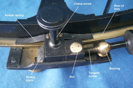
Figure 11: Tangent screw.
Figures 12 and 13 show the methods for adjusting the horizon mirror. The mirror bracket sits atop two circular tables. The top one may be tilted against a concealed spring using the adjusting screw, shown in Figure 13, to correct for side error.

Figure 12: Horizon mirror adjustment, side view.
The bottom circular table may be rotated through a small angle to correct for index error, using two capstan headed screws that lock against each other. The screws bear on a tongue which is an extension of the frame and the table rotates about an axis which passes through the frame and is secured by the large screw underneath.

Figure 13: Horizon mirror adjustment, rear view.
This rather complex arrangement is used on several sextants of this era. The sextant described in my post of 10 November 2009 shows an identical system, while another , shown in the post of 10 June, 2010, has a different though equally complex system. Before long, the much simpler method came in, of screws bearing against the back of the mirror with springs opposing the movement against the front of the mirror. However, some makers persisted with unreasonably complex systems of adjusting the horizon mirror well in to the twentieth century. Brandis was one late C19 maker whose system was copied for the US Navy Mark II sextant of the 1940’s and I have illustrated it in Figure 9 of my post of 30 November 2010.
Like many sextants that I can afford to buy, this instrument lacked a case. For the last nine years, I had been hoarding a case that had housed a pillar sextant. Usually, sextant cases are of mahogany, not brass-bound rosewood, indeed, this is the only example I have ever seen for a proper sextant, rather than the decorative so-called reproduction ones from the Indian sub-continent. Figure 14 shows how I have adapted the case for my Watkins sextant. Originally, it would probably have lived in a keystone case, which are difficult to make and difficult to carry. I had two contemporary telescopes saved against the day when I would acquire an antique sextant without any and had only to do a little screw-cutting on the lathe for them to fit in the telescope ring.

Figure 14: Sextant in new home.
This completes my one hundred and third blog post on sextants and, while I have material for two more, I will then have run out of subjects. I am open to suggestions about further subjects. If you have a particularly interesting sextant I would be happy to consider a guest post, though I would reserve the right to edit it if necessary. If you are interested in things navigational, don’t forget to have a look at my other site: http://www.chronometerbook.com

You must be logged in to post a comment.