Making a sextant monocular mounting

28 01 2009

In the Yaho sextants group recently, Mike Bowman of Darwin Australia asked about the availability of a prismatic monocular for his Freiberger Trommelsextant and Federico Rossi, writing from Italy, wondered about the possibility of cutting a pair of binoculars in half and mounting a half on a sextant. Had anyone experience of this?

Until this afternoon, I would have answered in the negative for myself, but wanting a break from writing my new manual on restoring the A10 and A 10A bubble sextants, I retired to the workshop for a few hours to see if I could prove a concept I had in my mind. It would be very difficult to retrofit a mounting like the one shown in the next picture, in which a huge 7 x 50 monocular is mounted on a 1957 Tamaya sextant as original equipment

Tamaya 7 x 50 prismatic monocular

Tamaya 7 x 50 prismatic monocular

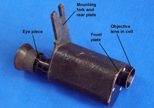
The mounting of the very old 10 x 30 monocular shown in the next picture gave me the germ of an idea that started me rooting around in one of my many treasure chests for a suitable piece of aluminium alloy plate.

Ancient prismatic monocular

Ancient prismatic monocular

In this ‘scope, the monocular backplate is continued as a fork that has a vee machined on one side. It was probably originally mounted on a top-of-the-range Heath and Co sextant, made around the beginning of the twentieth century, and there is no room for the fore-part of the monocular in a modern sextant, so I decided to use the objective lens mounting to hold a vee and flat type of mounting, to match the Tamaya shown above, as well as nearly all modern sextants.

I had only scraps of 4 mm plate in a suitable material, so screwed two pieces together to save having to convert a 12 mm hunk of material mostly to metal chips. I won’t bore you with all the steps, but the mounting started out as in the following picture.

Starting point

Starting point

After about three hours of machining, sawing and filing, it ended up like this:

Finished article

Finished article

The 4 mm plate is counterbored to a depth of 3 mm to accommodate the outside diameter of the objective lens mount while the threaded part of the lens mount passes through the smaller diameter hole and screws into its rightful place in the monocular, with an increase in optical path length of only 1 mm.  The next picture shows it in place.

Mounting in place

Mounting in place

It works well, but the weak point of the system, apart from the ease with which the threads of the objective lens mount can get crossed, is that when you halve most binoculars, you also have to halve the focussing arrangment. You can find binoculars with individual focussing, but these tend to be vintage WW II US Navy ones, worth almost as much as a second hand sextant of the same vintage. I haven’t for the moment any suggestions, but you can always let me have your ideas in the comments section; and you could encourage me by buying my book, The Naked Nautical Sextant and its Intimate Anatomy.


How flat are sextant mirrors?

27 01 2009

Recently I stripped some old sextant mirrors prior to re-silvering them. Since they were all from sextants of well-known makes and presumably satisfied their users, I thought to see just how flat the silvered surfaces were.

I placed them on an optical flat that had been made by the same person who ground the 1 metre telescope mirror of the Mount St John Observatory in New Zealand and illuminated them with an extended source of green light light from mercury lamps. The flat is known to be flat to within one tenth of a wavelength.

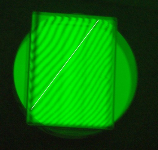
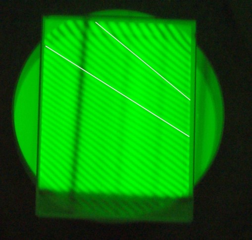
Without going into why we see interference bands, we can say that the dark lines you see represent contour lines on the mirrors, at intervals of half a wavelength. Perfectly straight, evenly spaced lines represent a flat surface. I have added a white line to help in seeing by how much some of the lines deviate from straightness (the coarser bands in the background are outlines of the battery of lamps). None deviated by more than half a wavelength.

Horizon Mirror 1916 Brandis and Co

Horizon Mirror 1916 Brandis and Co

Index Mirror. C19 Crichton.

Index Mirror. C19 Crichton.

Index Mirror, 1938 Hughes and Co

Index Mirror, 1938 Hughes and Co

Horizon mirror 1920's Heath Sounding sextant

Horizon mirror 1920’s Heath Sounding sextant

I have in the recent past replaced old mirrors with new ones cut for a few dollars from pieces 4 mm-thick modern float mirror glass, without being able to detect any loss of performance. I wondered how it would compare with the optically worked examples from the past, so I stripped a piece to try it.  The following image shows that it compares very well and offers a much cheaper solution than buying a new one, often for several tens of dollars. So how flat do sextant mirrors need to be?

Modern commercial 3 mm float glass

Modern commercial 4 mm float glass

P.S. Visit NavList for February 09 to see some responses to this question.


Tamaya switch overhaul

9 01 2009

Most of the early Tamaya sextants and clones had the same design of battery switch, but I haven’t seen a modern one with two AA batteries for some time. I would expect Tamaya, in common with other makers, to have stuck with a simple design that was easy to overhaul at sea. This is what one of mine looks like:

100_2278

Electricity flows from the positive battery contact clip through a short length of wire to the switch contact. Pressing the switch button causes the plunger, seen as a screw head, to bridge the gap to the other switch contact, allowing electricity to flow through a wire, poorly seen in the area of the switch, to the lamp. The circuit is completed via the frame to the negative battery contact ( and yes, I do know the electrons flow in the opposite direction).

Apart from bits breaking off, the battery going flat or the lamp burning out, what can possibly go wrong with such a simple arrangement? The short answer is “Anything that breaks the circuit”, but I’ll confine myself to the switch to begin with.

The switch contacts can get dirty or corroded and the same goes for the battery clips. The latter are easy to see and to get at to clean, so check those first. Even if they look fine, it does no harm to freshen them up by rubbing the contact areas with fine, e.g. 240 grit, emery paper. The switch contact areas are easy to get at. Simply remove the two screws that hold them to the handle and clean the undersides where they make contact with the plunger. While you’re at it, press the push-button in to prevent it from rotating and unscrew the plunger, taking care not to lose the spring that lies under the push-button. The head of the plunger, simply a shouldered screw, can then be freshened up too. Once the switch contacts have been removed, this is what you may see:

100_2281

Note the bare copper wires that, given a chance, oxidise to a black, non-conducting colour.  You can freshen these up too, but a better course is to replace the short piece of wire with new, tinned wire (a piece of 15 A fuse wire will do) and to tin the end of the wire to the lamp with solder if you have a soldering iron and can use it. The other improvement you can make is to put the wires where you can see them, on top of the switch contacts rather than hidden underneath them, like this:

100_2284

As a refinement, with a sharp knife cut a gasket from neoprene sheet to protect the contact area from salt water:

100_2277

Assembly is the opposite of disassembly, except for placing the wires on top of rather than under the switch contacts. When replacing the switch plunger, take care not to overtighten as you screw it into the the push button. If you are too rough, you may split it and will then have to go shopping for some Araldite. The spring belongs underneath the button.

100_2282

If replacing the battery and lamp and overhauling the switch doesn’t restore function, the fault most likely lies in the wire between the battery handle and the lamp, and it is most likely to break at the lamp itself. But that’s for another day.

You can read about other types of lighting systems as well as gain a knowledge of the detailed structure of your sextant(s) by buying my book The Naked Nautical Sextant and its Intimate Anatomy. Read what Trevor Kenchington has to say about it in “Inside the book”.


Evolution of the Sextant Micrometer

3 01 2009

See also the post for 4 November, 2012, “Fleuriais’ Marine Distance Meter”.

Some time in the first ten years of the twentieth century, possibly in 1907, Carl Plath introduced the micrometer sextant to navigators. It was not claimed that the micrometer sextant was more accurate than the vernier type, rather that it was easier and quicker to read. The National Maritime Museum at Greenwich has an example dating to about  1917:        http://www.nmm.ac.uk/collections/explore/object.cfm?ID=NAV1130&picture=1#content.  The instrument shown is missing the fixed part of the release catch, not the first I have seen in this condition.

The micrometer reads to one  minute and the mechanism of the Plath release catch appears to have remained the same right through to the Second World War and beyond, when manufacture was continued as the USSR Navy SNO-M sextant. From about 1940, Tamaya also began to produce a sextant that was in every respect identical to Plath’s design. The following photo is of an early Tamaya, serial number 606 (Figure 1).

100_10562

Figure 1 : Early Tamaya micrometer sextant

Figure 2 shows a detailed view of the micrometer mechanism. If you look at the preview of The Nautical Sextant, you will see its close similarity to the USSR SNO-M, which in turn is identical in practically all respects to the wartime C Plath.

micrometer-detail

Figure 2 : Details of Plath-type micrometer mechanism.

Apart from the scale illumination system, the sextant could be a C Plath of the same period. Perhaps it was. In the nineteenth century, it was common for sellers to put their own name on a sextant made by someone else and Tamaya may have continued the practice into the twentieth.

In about 1909 Heath and Co. introduced their “Hezzanith endless tangent screw automatic clamp” which incorporated all the elements of a micrometer sextant but without a micrometer drum. It allowed rapid positioning of the index arm followed by fine adjustment, but the readout was still from a vernier main scale. The patent document concluded:

100_1704

Figure 3: Heath’s Patent rapid release clamp

However, C Plath may well have preceded Heath and Co, for Brent Evers recently sent me some photogaphs of an instrument in his possession that differs in no essential respect from Heath’s  rapid release mechanism . The instrument frame is the Dreikreis (three circle) pattern (Figure 4) .

Figure 4 : C Plath Dreikreis sextant with rapid release clamp. Copyright Brent Evers, with permission.

There is a finely skew-cut rack on the back of the limb, with which a worm engages. The worm runs in bearings on a swinging plate between two centres, so that it can be swung out of engagement with the rack against  pressure, by squeezing two knobs between finger and thumb. A helical spring between the knobs keeps the worm in engagement.  A leaf spring provides axial preload to eliminate end-float of the worm spindle (Figure 5)

Figure 5 : Detail of Plath rapid release mechanism. Copyright Brent Evers, with permission

The near-identity of the two mechanisms is very evident from even a cursory inspection of Figure 6, which details Heath and Co’s patent rapid release clamp. The only point of difference is that Heath used a folded leaf spring between the two release clamp knobs to keep the worm in engagement.

Figure 6 : Heath and Co’s rapid release clamp mechanism

I am inclined to believe that Heath copied from Plath rather than the other way around, as the Plath instrument has a serial number in the low one hundreds, which would place it firmly in the nineteenth century, and the parts of the swinging plate have been fabricated, rather than employing a casting as Heath did. The Plath instrument may even have been a prototype. However, the serial number, placed at the left end of the limb, may have been from a separate series, as the sextant also has the  stickman “Sunseeker” logo (registered in 1905) and is named “C PLATH HAMBURG” in the centre of the limb,  in their very characteristic font. But we know that Plath had introduced a far superior design of micrometer mechanism by 1908, so it is most likely that Heath copied a mechanism that Plath had abandoned.

Note: (added 21 July 2011) I have since come across a Plath instrument with a serial number that places it in the late 1920s, though it has an archaic Plath frame. It has the same fine adjustment mechanism as the apparently earlier instrument.

In the early thirties, Heath and Co, by now merged with W F Stanley and Co., made the logical step of increasing the pitch of the rack and adding a micrometer drum:

copy-of-heath-micro3

Heath and Co was unusual in placing the rack on the back of the limb, whereas all other makers placed it on the edge, including Brandis, who by 1931 had produced a micrometer sexant of conventional design.

By the mid 1930’s,  the other main sextant maker not mentioned so far, Hughes and Son, had begun to produce a micrometer sextant. Until recently, I had thought that this had arrived without an intermediate step between the vernier and micrometer, but a few days ago a “missing link” came into my hands. It seems at first sight to be  a typical Hughes three ring vernier sextant, but the rear edge of the limb is provided with a rack and there is a micrometer worm with release catch, but no micrometer drum. Unlike nearly all other micrometer sextants except the USSR Navy SNO-T and the Italian Filotecnica Salmoiraghi, the micrometer worm is cylindrical rather than conical, in this case because there was no need to angle the shaft to accommodate a micrometer drum.  The pitch of the worm is 18 turns per inch, so a micrometer drum divided into 60 arc minutes could easily have been added, except that the radius of the rack was rather too large, at about 6.7 inches (170 mm). The following three photographs give details of the mechanism of this rare sextant, whose serial number places it in 1931*:

Micrometer, front view

Micrometer, front view

Micrometer, rear view

Micrometer, rear view

Micrometer, exploded view

Micrometer, exploded view

The final version of the Hughes micrometer, continued right until the end of manufacture in the late 1960’s, is shown below. The conical worm is still of 18 t p i (M 1.41), but the pitchcircle radius of the rack has been reduced to 6.366 inches (161.70 mm).

Hughes micrometer, final version

Hughes micrometer, final version

Quite why makers other than C Plath were slow to introduce the micrometer is not clear. It was described by Hero of Alexandria, so was not patentable. Perhaps navigators of the time were conservative.

Lovers of detail will find much more about the detailed structure of the nautical sextant in my book, The Nautical Sextant .

* I have since come across the same model with a 1925 serial number.