This post is preceded by “Tamaya Collimation Blunder”
In a NavList post for 4th October 2013, Paul Werner wondered whether perhaps the horizon shades of his SNO-T had been incorrectly assembled. There is a method of bringing down the sun to the horizon which involves setting the sextant to zero, pointing the instrument at the sun and then rotating the index arm while keeping the reflected sun in sight until the horizon appears. I find it a very easy method with the sun and a nearly essential one for star observations. Paul was troubled by a crescent of direct sunlight getting into the field of view at the lower left side of the field of view beneath the horizon shades, and was worried that his eyesight might thereby be damaged. I had noticed the effect too but had thought little about it, probably because I had got into the habit of keeping the images well into the right of the field of view.
When I trawled through photographs on the internet of SNO-T sextants, they were all assembled just like Paul’s sextant and Alex Eremenko reported that his sextant had arrived in the factory wrappings in exactly the same way (Figure 1). It scarcely seemed possible that all the SNO-T sextants I could find had been assembled incorrectly, but when I remounted the shades, supposedly upside down, it was immediately obvious that this was in fact the correct way, as Paul’s problem had disappeared. There was still the possibility of direct light getting between the bottom of the index shades and the top of the horizon mirror, but this only occurred with the top shade on its own, which in my sextant is the lightest (numbered “4”) and therefore least likely to be used on its own for sun sights.

Figure 1: Horizon shades as fitted.
For those SNO-T sextant owners who wish to remount their horizon shades, this is how to do it. First remove the shades assembly from the frame by releasing two 4 mm screws (Figure 2). You can enlarge all the photos by clicking on them. Return to the text by clicking on the back arrow at top left.
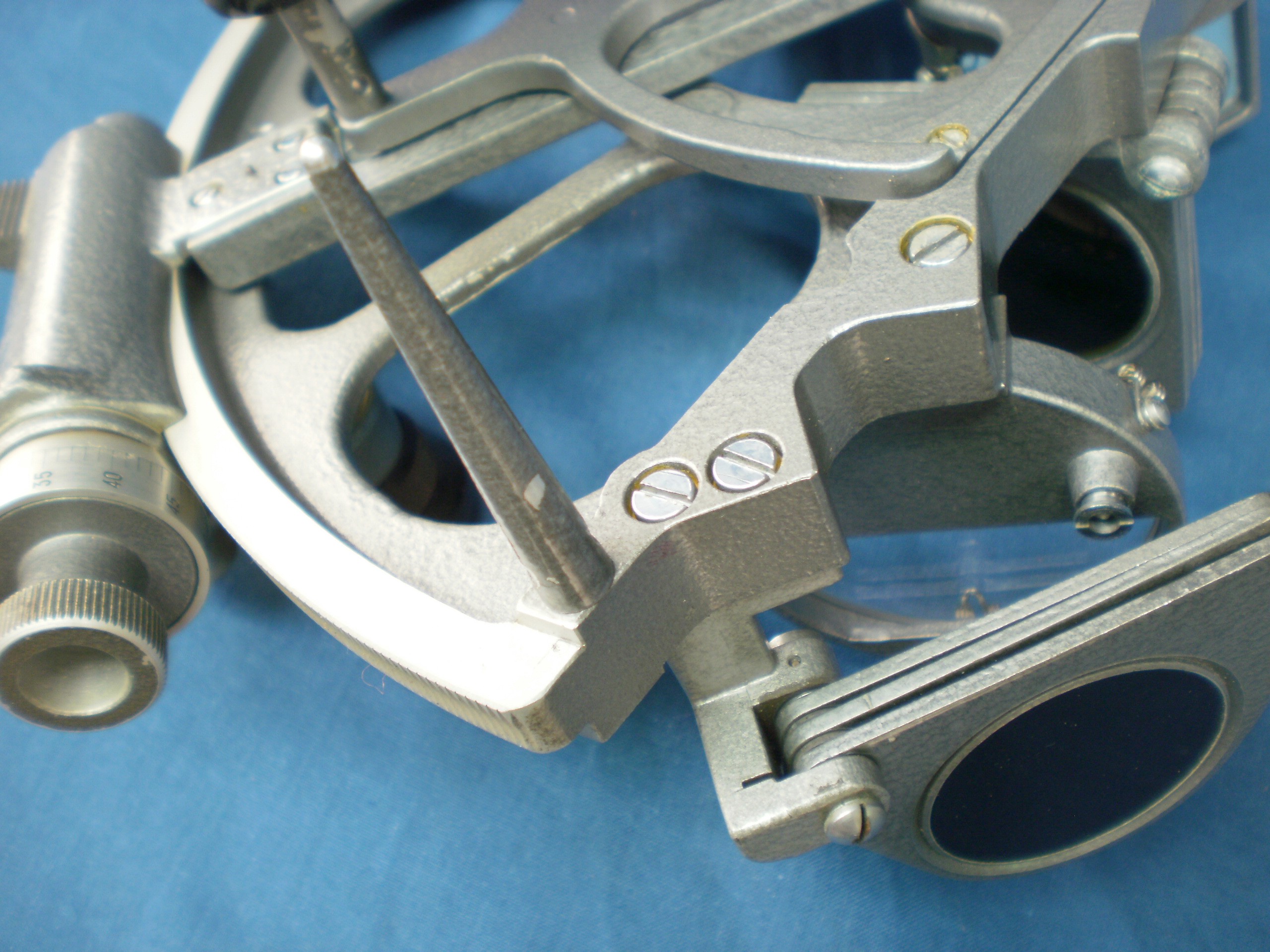
Figure 2: Remove 2 screws.
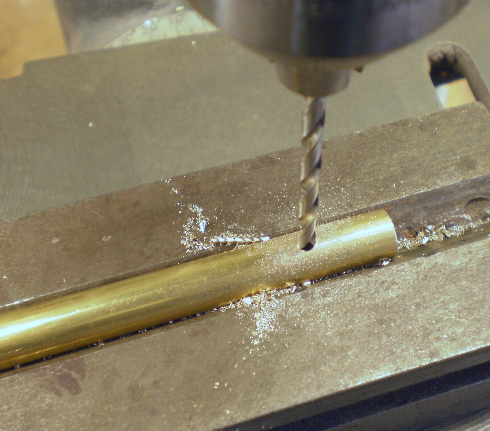
The small end of a taper pin can be seen in the far bearing for the shades mounting pin in Figure 2. It prevents the mounting pin from rotating and must now be drifted out. This is not altogether an easy task, as the small end of the pin cannot be accessed from directly above because the base of the bracket is in the way, and so the drift has to be struck at an angle. It is very important that the bearing is supported as close beneath the large end of the taper pin as possible, since aluminium alloy castings tend to give no warning that they are about to break if stressed unsupported. Figure 3 shows the casting supported at both ends by the jaws of a vice. The adjusting screw should also be slackened off a few turns. A short piece of an old bicycle spoke ground down to size makes a good drift and you may have to give the short end of the taper pin quite a hard blow to get the pin moving. Once it does so and there is something of the large end to grip with a pair of pliers, the removal can be completed with a twisting pull. If the taper pin will not move after having been struck as hard as you dare, apply some releasing compound and try again the next day.

Figure 3: Drift out taper pin.
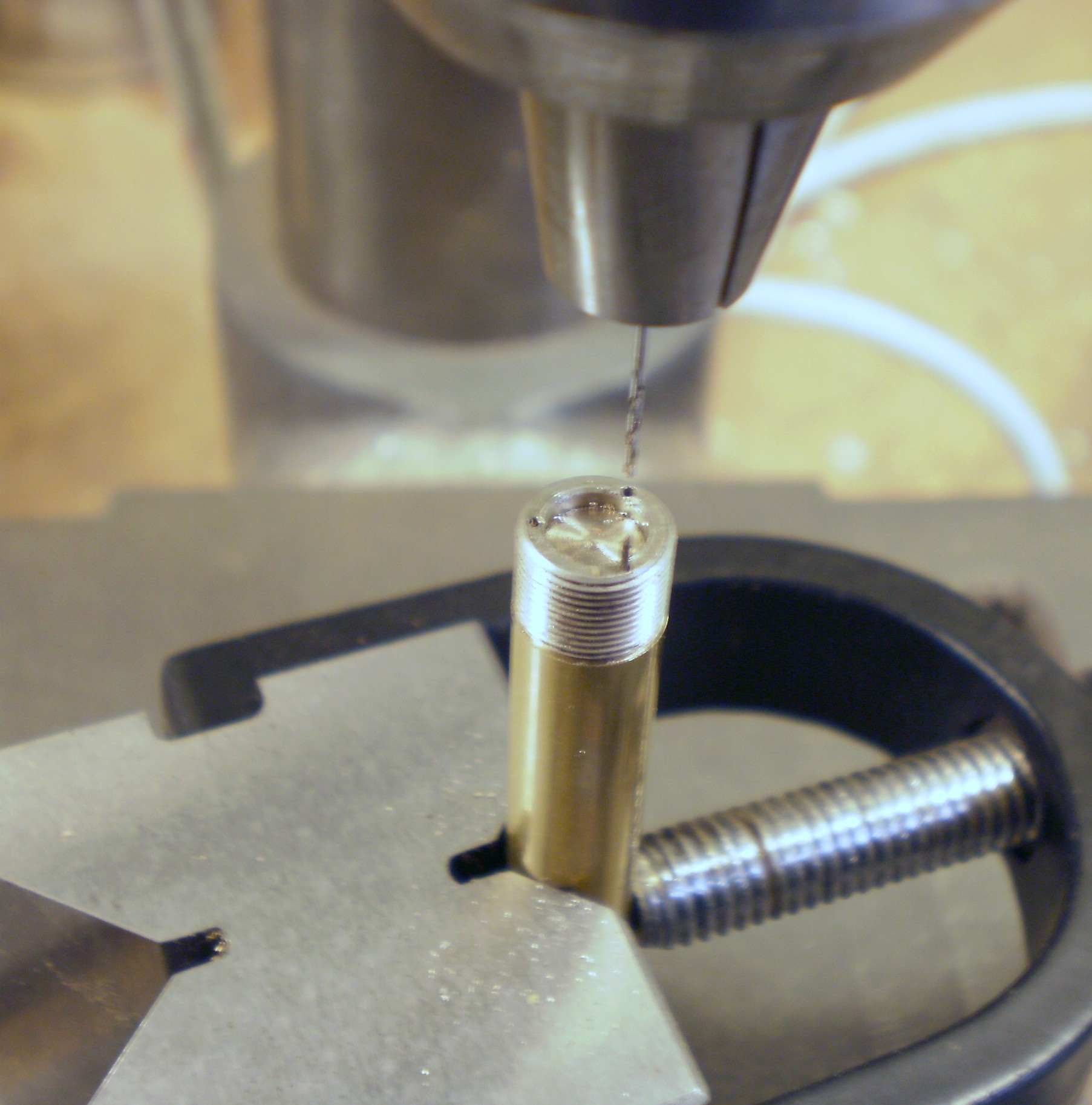
The mounting pin then has to be drifted out with a drift that fits down the hole for the screw (Figure 4). Do not be tempted simply to loosen the screw and hit its head. This is a good way to bend the rather narrow screw, which then tends to break off when it is re-straightened. Experience is a good teacher to those who listen.
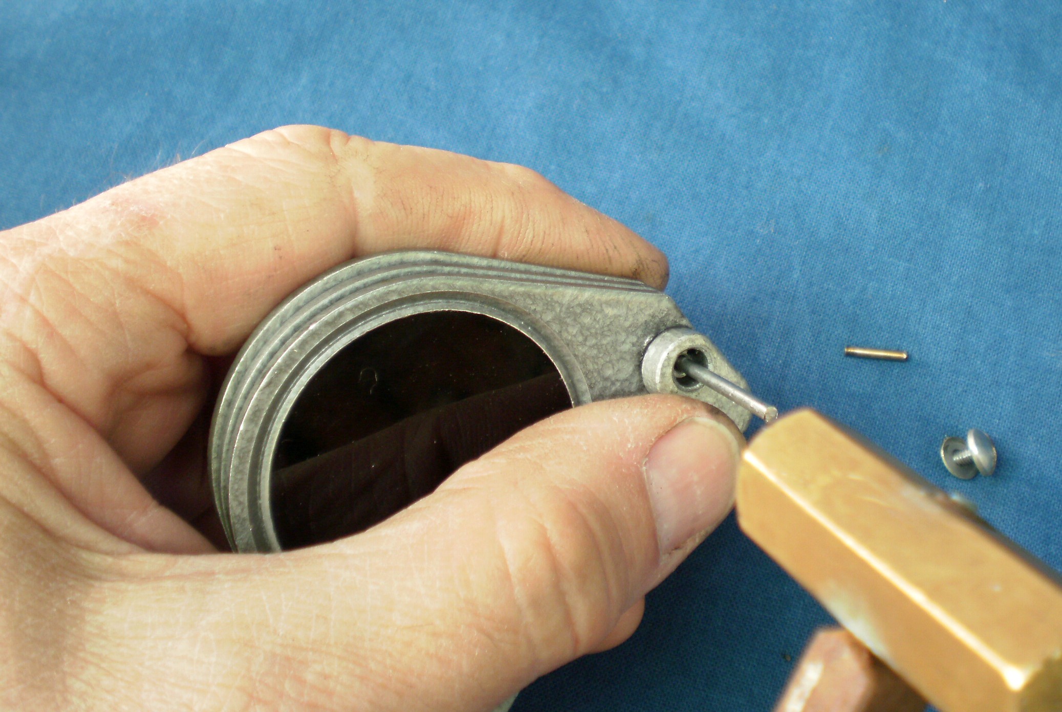
Figure 4: Push out mounting pin with drift.
The assembly can now be taken completely apart for cleaning (Figure5). Note that the washers that fit between the shades have internal keys that fit into a longitudinal keyway machined into the mounting pin, so that they cannot rotate. This prevents rotational forces from being transmitted from a shade to its neighbours, so that they can all be rotated independently.
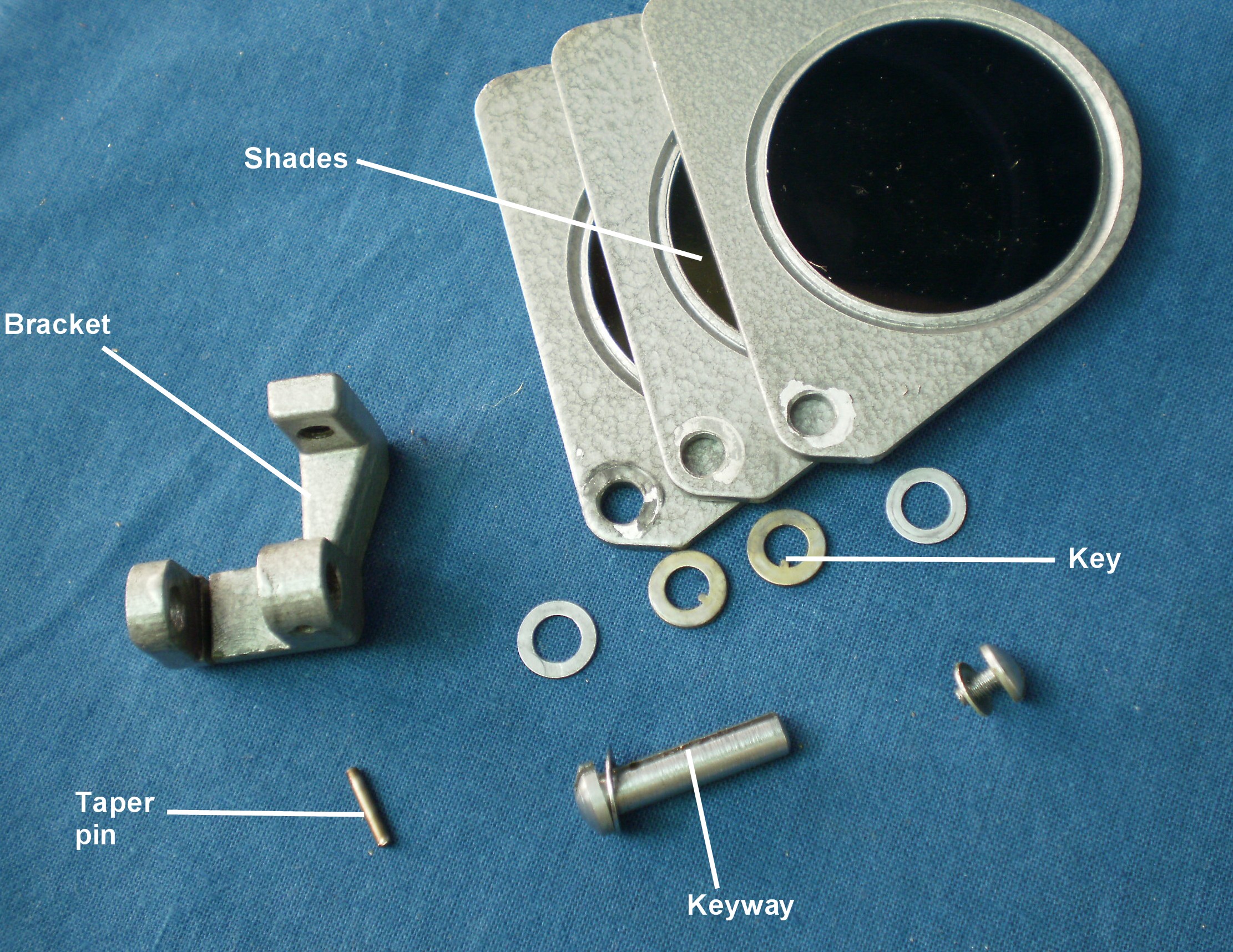
Figure 5: Shades assembly exploded.
When re-assembling, I find it is helpful to apply a smear of waterproof grease to the mounting pin and a somewhat thicker smear to each side of the washers. This seems to help them to stay together. Mount the shades and their washers on to the mounting pin and manoeuvre the edges of the shades and washers between the uprights of the brackets (Figure 6).

Figure 6: Placing shades between uprights.
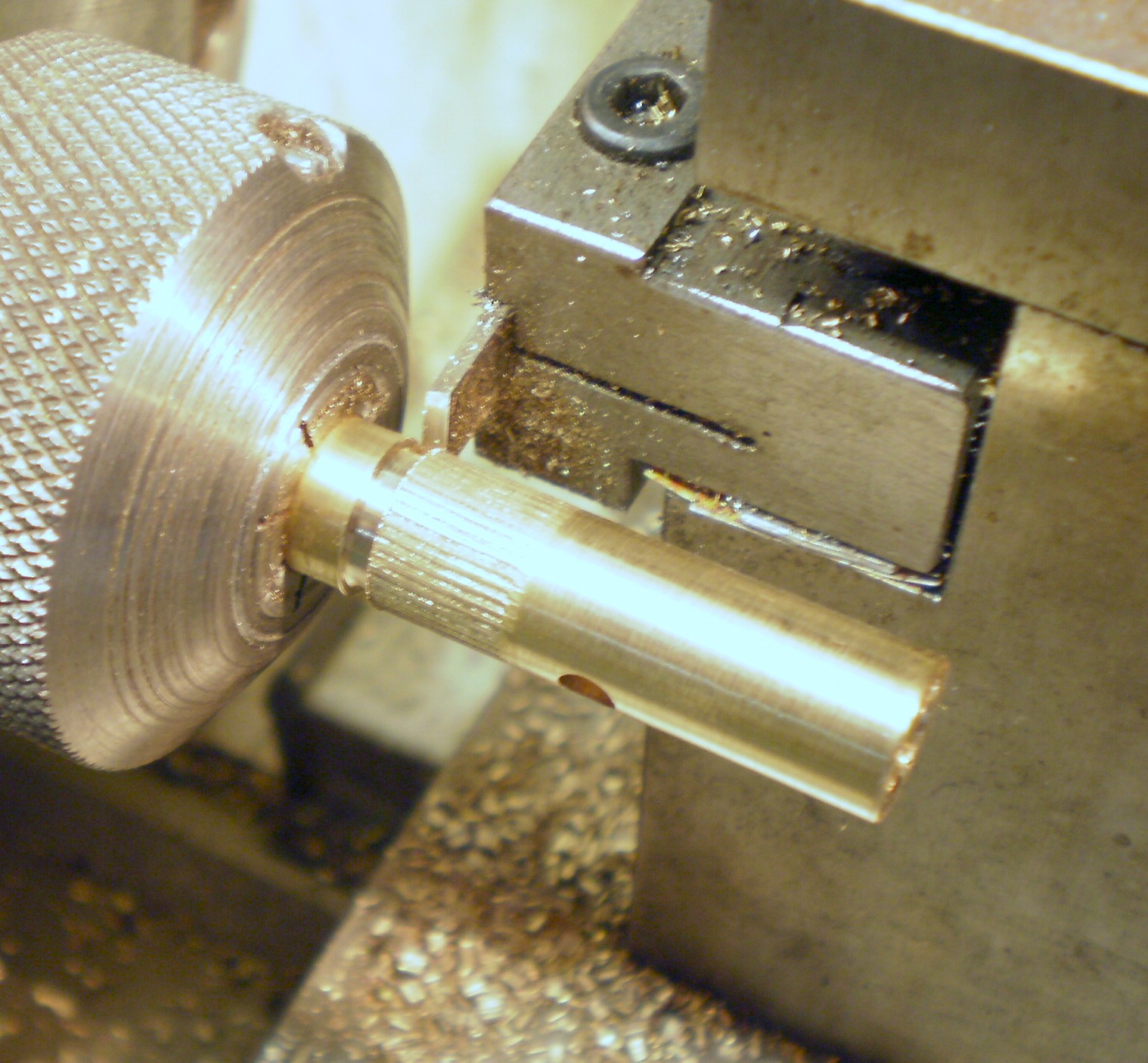
Holding the sandwich of shades and washers firmly together, slide out the mounting pin and slide the sandwich into line with the holes in the uprights. Then reinsert the pin (from the correct end!) and wangle it through the sandwich and out the other side (Figure 7).

Figure 7: Shades and mounting pin in place
The hole in the mounting pin is then lined up with the holes in the upright and a new, greased taper pin inserted (Figure 8). You can of course use the old pin, but if you use a new one, you can leave it as long as you like for easier removal, which is especially useful if you find you have remounted the shades just as they were before…
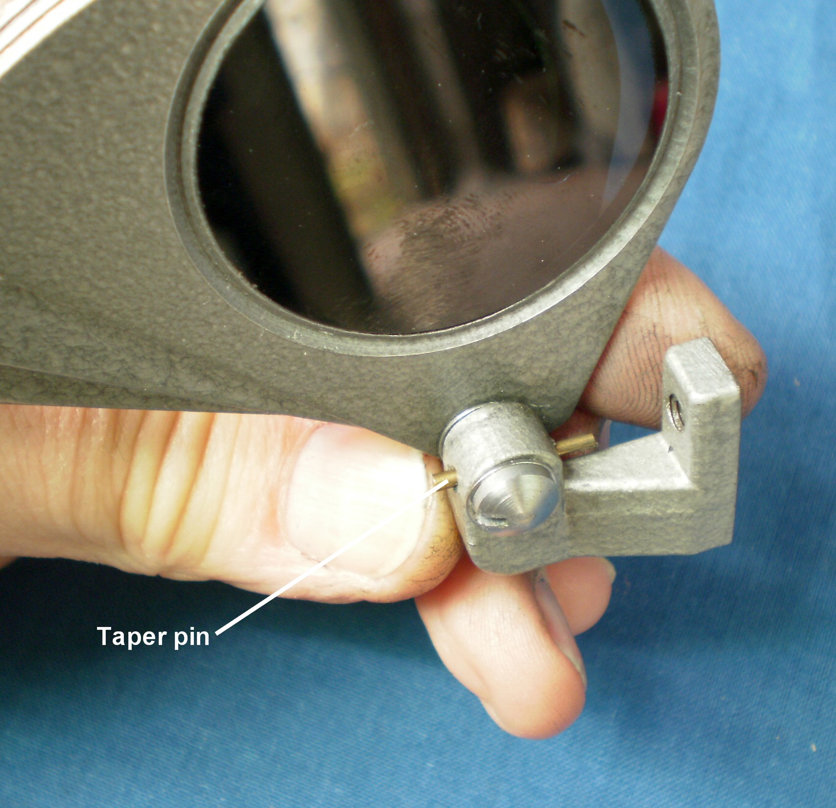
Figure 8: New taper pin in place.
Figure 9 shows the shades remounted on the sextant in their new, improved, correct orientation. It is now obvious that direct rays of the sun can no longer reach the telescope either above or below the shades.
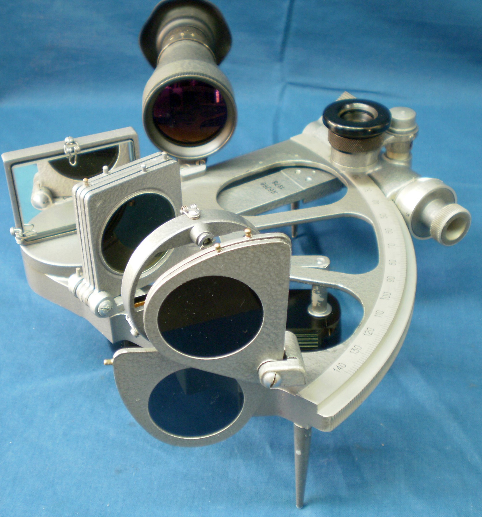
Figure 9: Shades now correctly mounted.
If you have enjoyed reading this post, you will I am sure enjoy reading my books, “The Nautical Sextant” and “The Mariner’s Chronometer”. You can read what others think of them by logging on to Amazon and looking for the titles under “books”.


You must be logged in to post a comment.