Previous posts in this category include: “A C18 sextant named J Watkins”, “An Old Wooden Quadrant Restored”, ” A turn-of-the-century French sextant”, “A Half-size Sextant by Lefebvre-Poulin”, ” A Fine Sextant by Spencer, Browning and Co”, “A C19 Sextant Restoration” , “Making a Keystone Sextant Case” , “Restoring a C. Plath Drei Kreis Sextant” , “Heath Curve-bar sextant compared with Plath” , “A Drowned Husun Three Circle Sextant”, ”Troughton and Simms Surveying Sextant” , “A Sextant 210 Years On” , “A fine sextant by Filotecnica Salmoiraghi”, “A British Admiralty Vernier Sextant”, “An Hungarian Sextant via Bulgaria” , “A Half-size Sextant by Hughes and Son” and “A Fine C Plath Vernier Sextant”, “Heath and Co’s Best Vernier Sextant.” and “An Early C19 Ebony Quadrant Restored”.
Two thousand and nineteen was a busy year for me and now that 2020 is upon us I find that I have not written a post in this blog for about a year, though not for want of trying, as I see that I got as far as writing the title of this one in August, 2019, having bought the instrument in April. My chronometer blog (www.chronometerbook.com) fared a little better, with one post. I have begun to make a catalogue of my nautical sextants and related instruments, and this morning found that I had omitted to describe a survey sextant that I acquired in 2013, so I will try to write about that after this one, in between mending and rating chronometers.
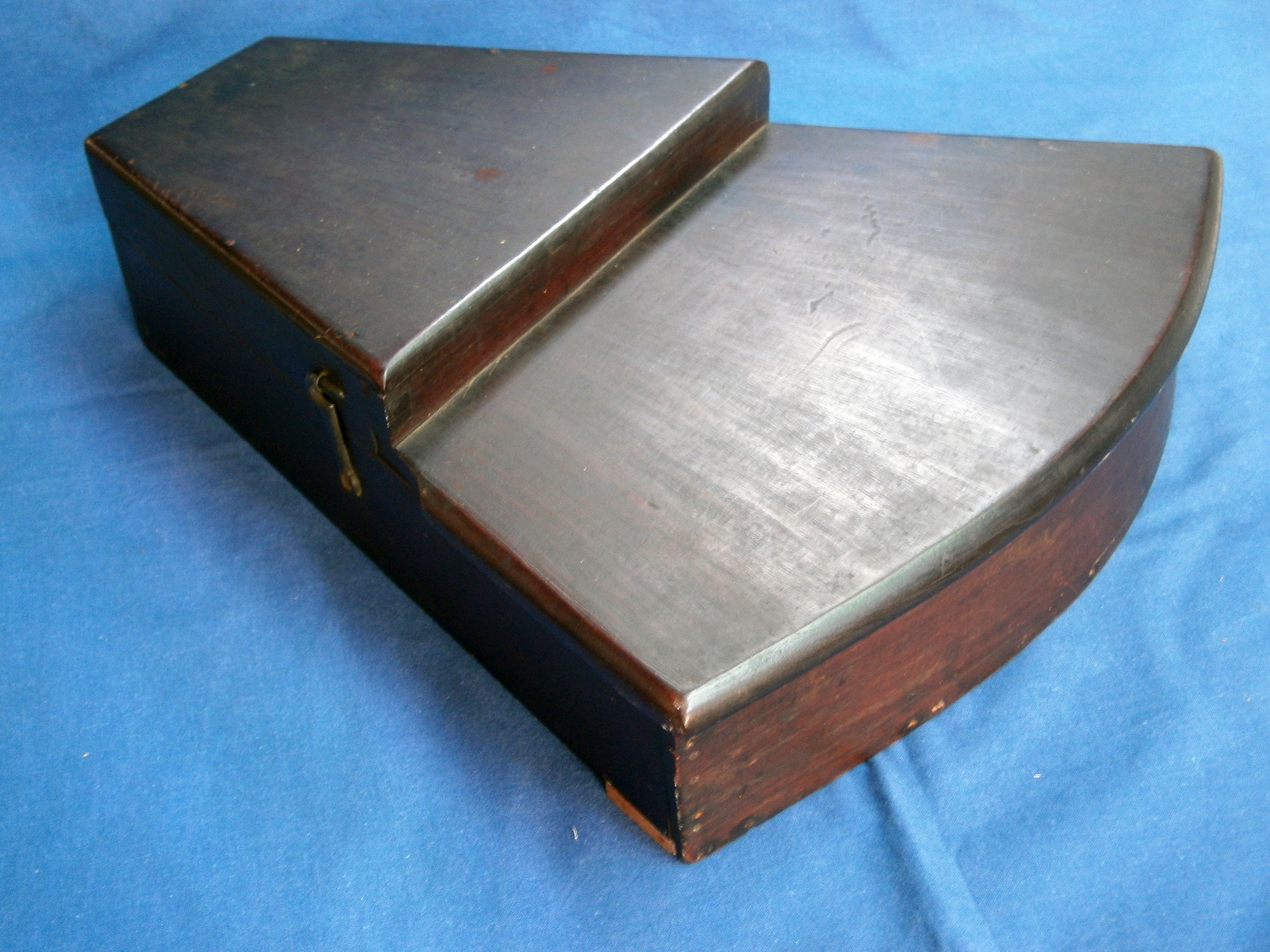
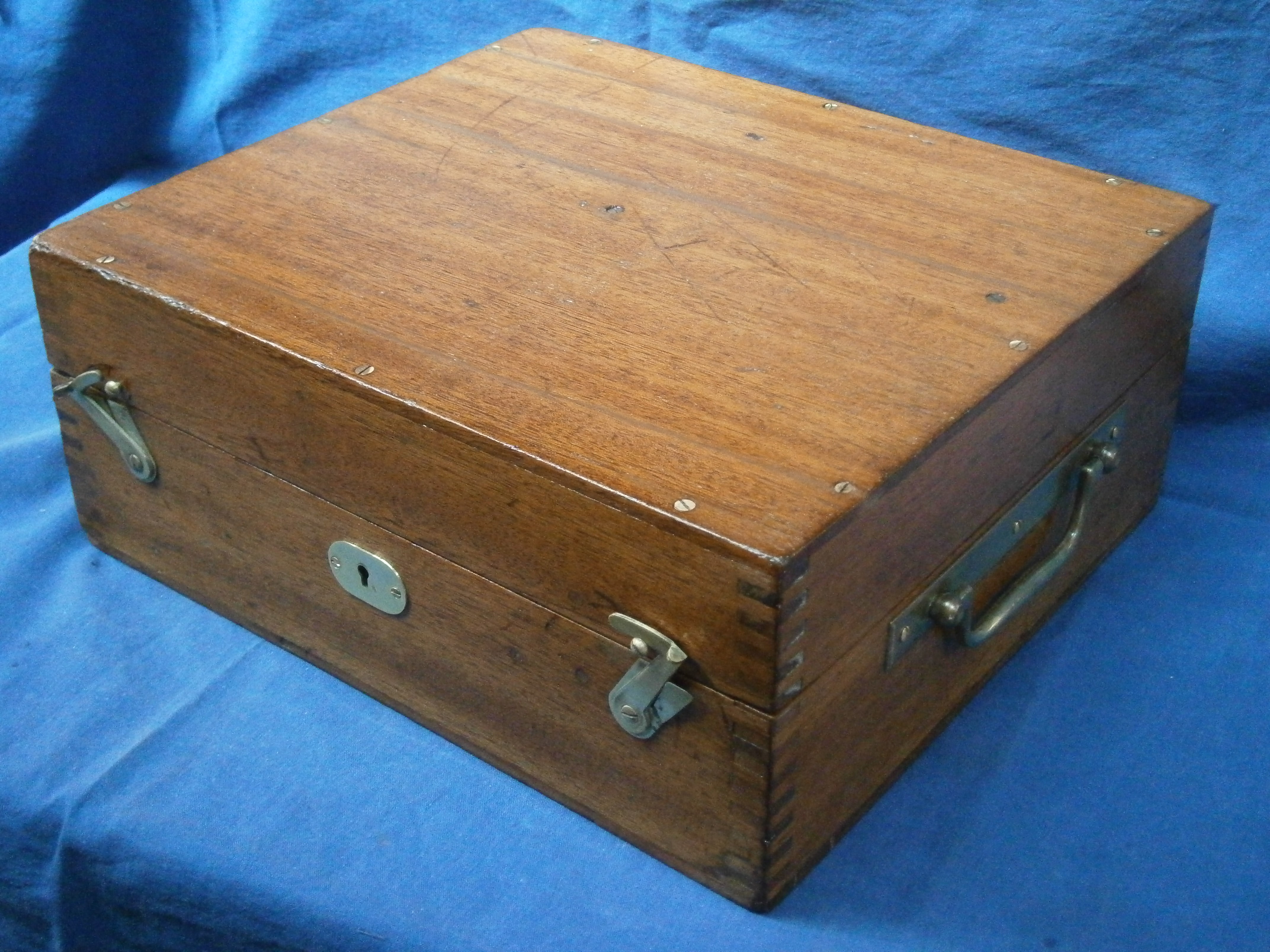
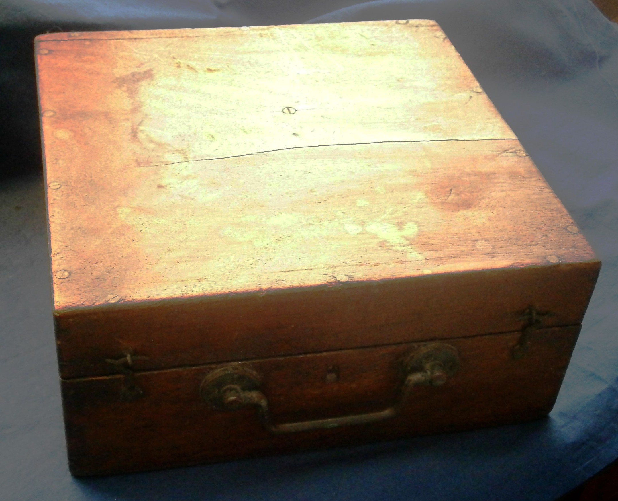
Figure 1) Case exterior.
All the photographs are of the instrument after restoration. For some reason, I did not think to take photographs as I proceeded. Except for a small area of the case at the bottom right and a re-positioned hinge, the case was intact. The stepped case looks rather archaic and I have come to associate it with early American instruments, or rather, instruments sold in America. If any one knows something different, I would be glad to hear of it. Where it is un-stained, the timber is light brown, but I am inclined to doubt that it is mahogany. Again, American readers may be able to inform me.
The octant came to me missing two of its legs and its peep sight. Fortunately, I could copy the remaining leg, and for the peep sight I had a model of the pillar that I could copy from a restoration described in my post of 13 June, 2018.
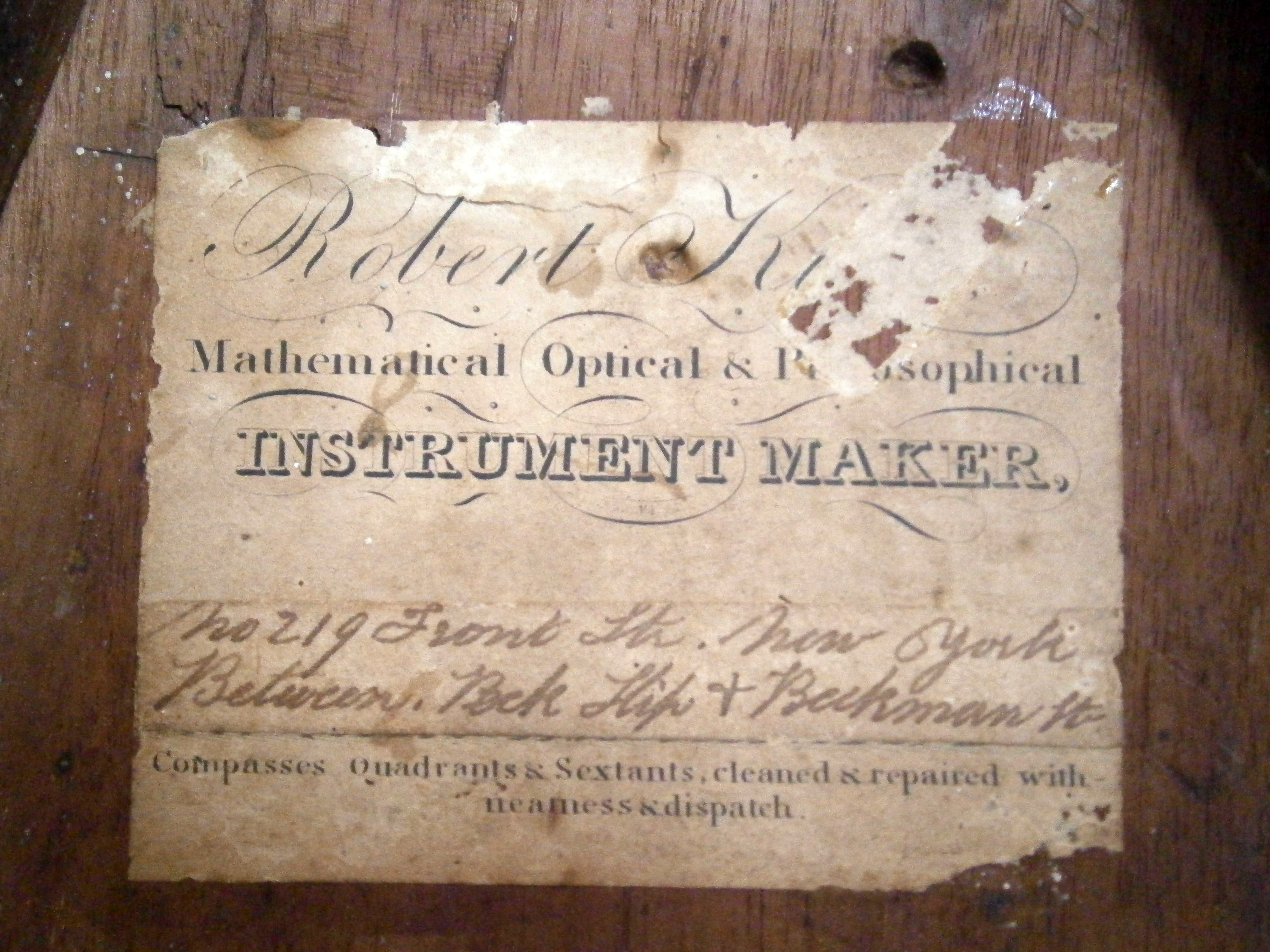
Figure 2: Seller’s label.
A seller (there may have been others) was “Robert King of 219 Front Street, New York. Between Beekman Street and Peck Slip.” The hand-written address is pasted on top of the rest of the label. All these names still exist, but unless 219 was down an alley way, it has been replaced by a modern-looking frontage. Perhaps someone in New York can add information that it not available by my having looked on Google Earth. I have not been able to discover when Robert King was active as it is unfortunately a very common name. Very many instrument makers did not actually make the instruments that they sold and this applies particularly to sextants, because of the requirement for a large and expensive dividing engine. It may be that they sometimes assembled instrument from major parts and possessed enough skill to carry out overhauls and repairs. (See end note).
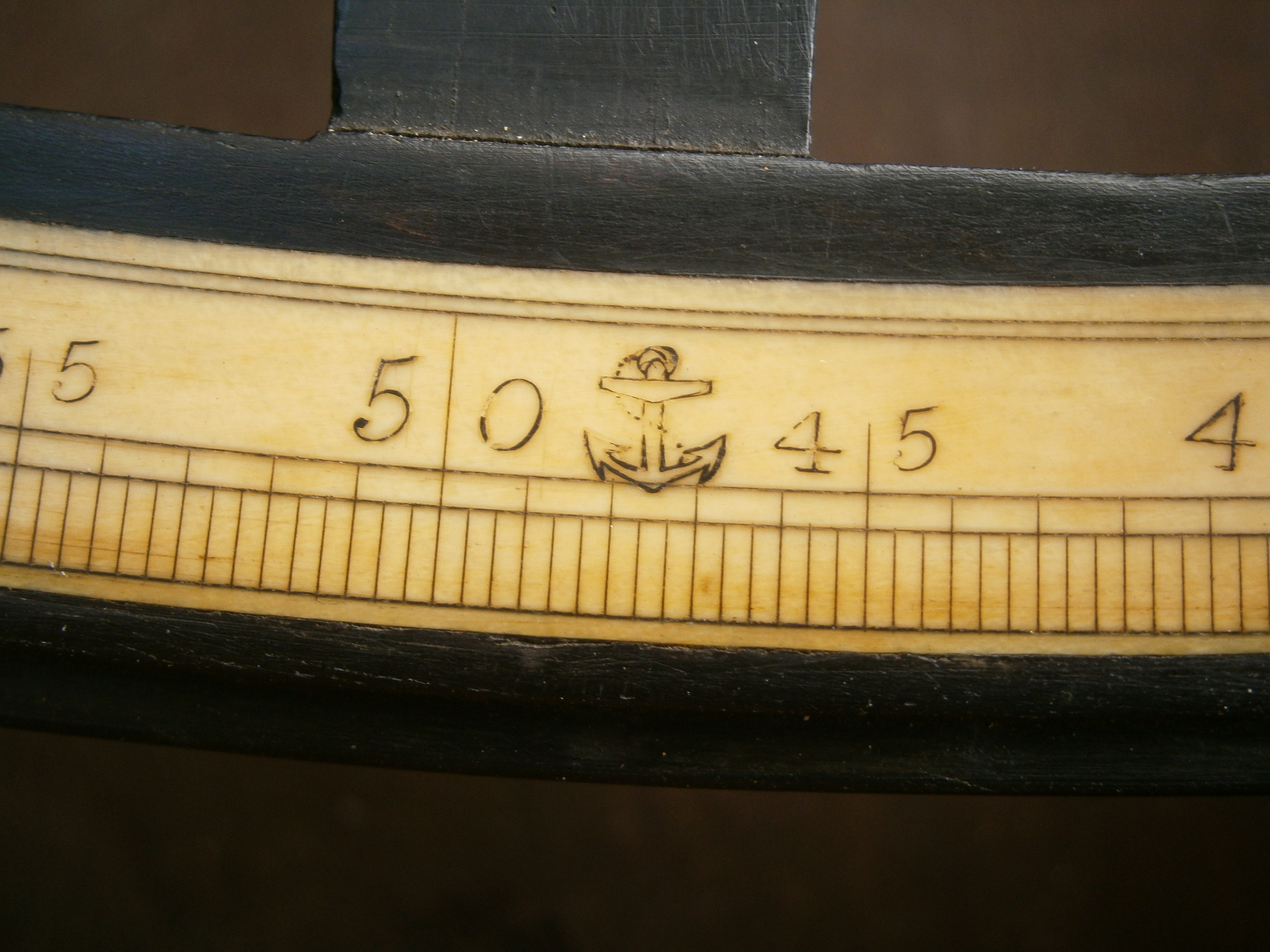
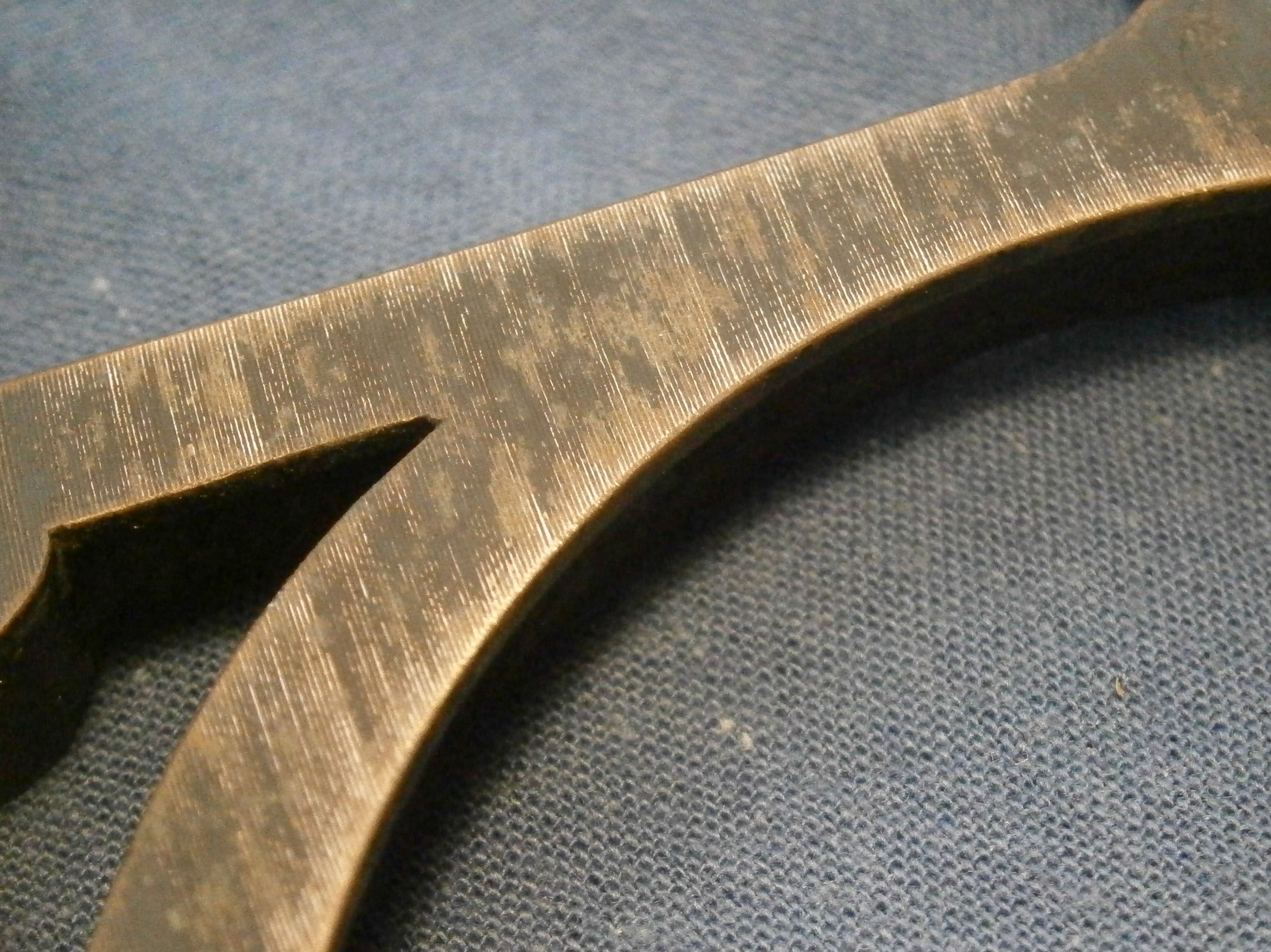
Figure 3: Divider’s logo.
We can be sure that King did not make the frame of this instrument and it is very unlikely that he made any other parts. Figure 3 shows the central part of the arc, which has a very clear fouled anchor logo. This is usually associated with instruments divided by Jesse Ramsden after completing his second dividing engine in about 1774, with the logo flanked by the initial letters I and R. It may be that Matthew Berge, who took over the business after Ramsden’s death in 1800, continued to use the logo as a sign of excellence, though without the initials. Berge’s price list for 1801 shows him selling “Hadley’s Octants in ebony with ivory arches” for between £2 5s (£2.25) and £5 5s (£5.25). Families of the time could get by on about £40 a year and be comfortable on £100, so even a cheap ebony octant represented a considerable investment.
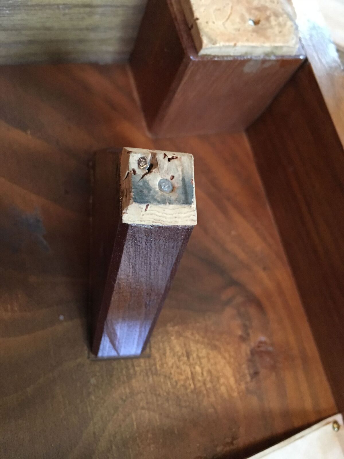
However, King may have carried out a repair on the octant as shown in Figure 4. An area of weakness where the index shades are mounted could have led to splitting of the ebony frame along the grain. This area has been reinforced by letting in a slip of brass, secured at one end by a screw.
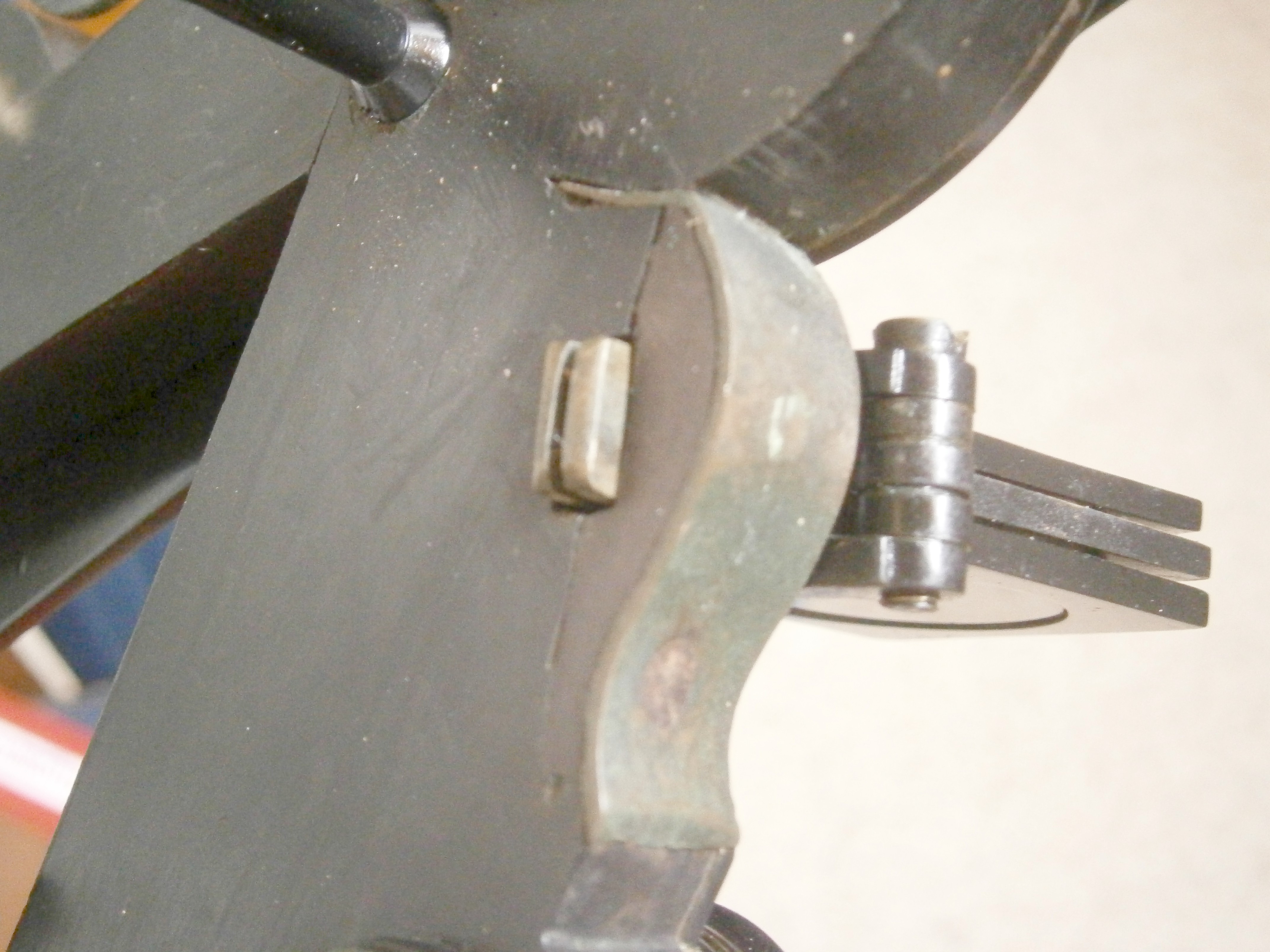
Figure 4: Repair to frame.
Early quadrants, which were divided by hand, necessarily had to have large radii, of about 380 mm (15 ins), and they were not provided with a handle. My quadrant has a radius of about 290 mm (11.5 ins) and has no handle, so while the design is archaic, it must have been made in the 1770s or later. Another ebony quadrant that I have is of about 250 mm (9.8 ins) radius and has a typical handle, so is probably later.
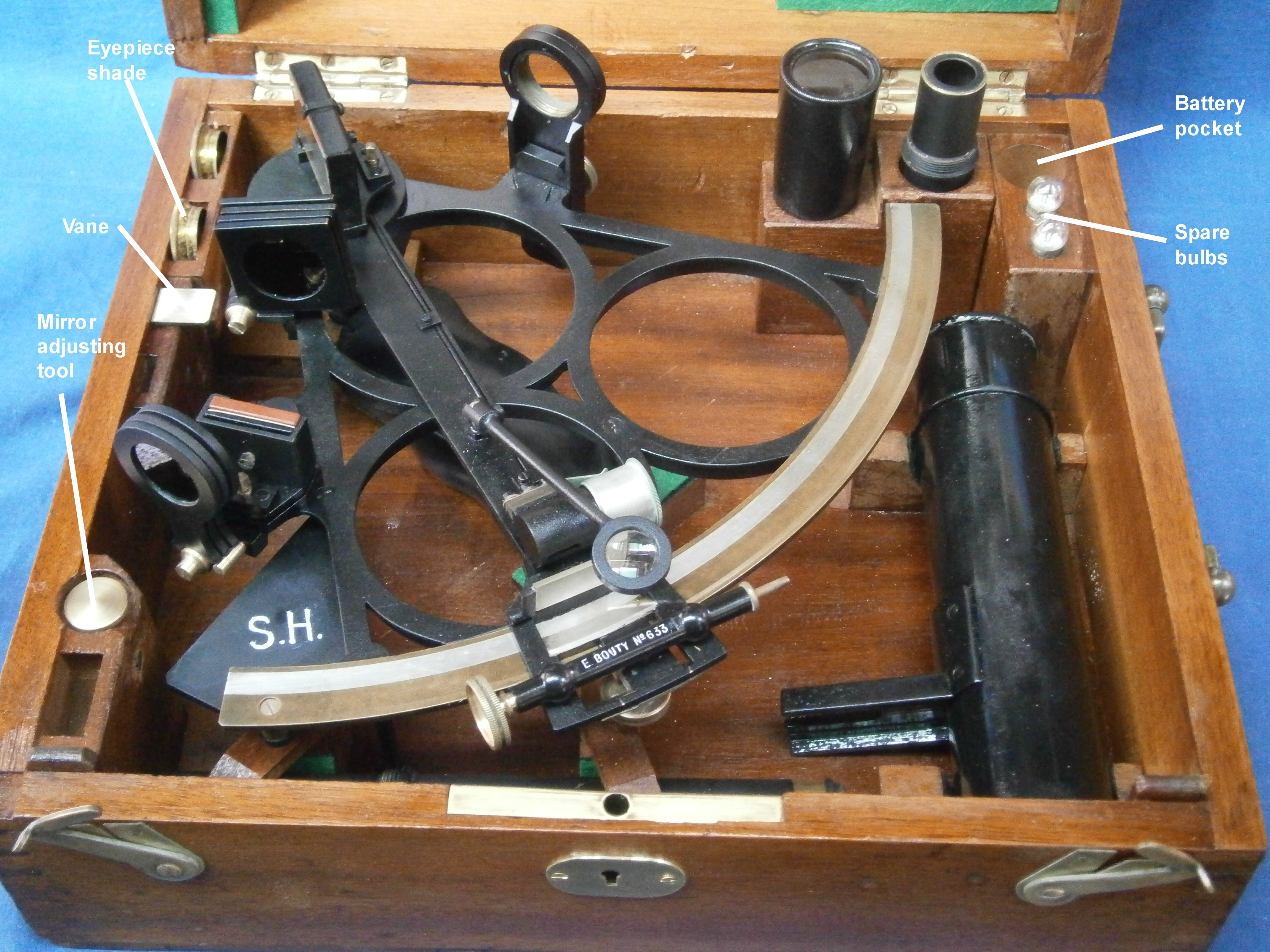
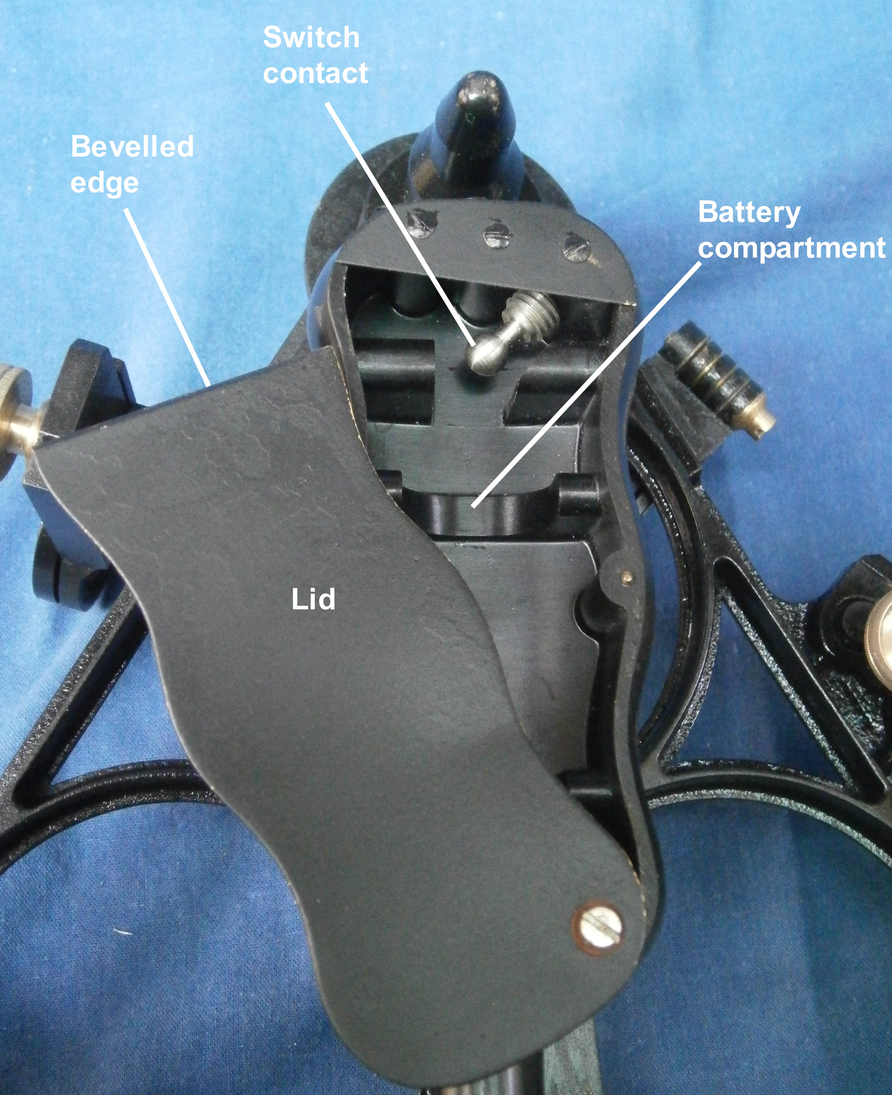
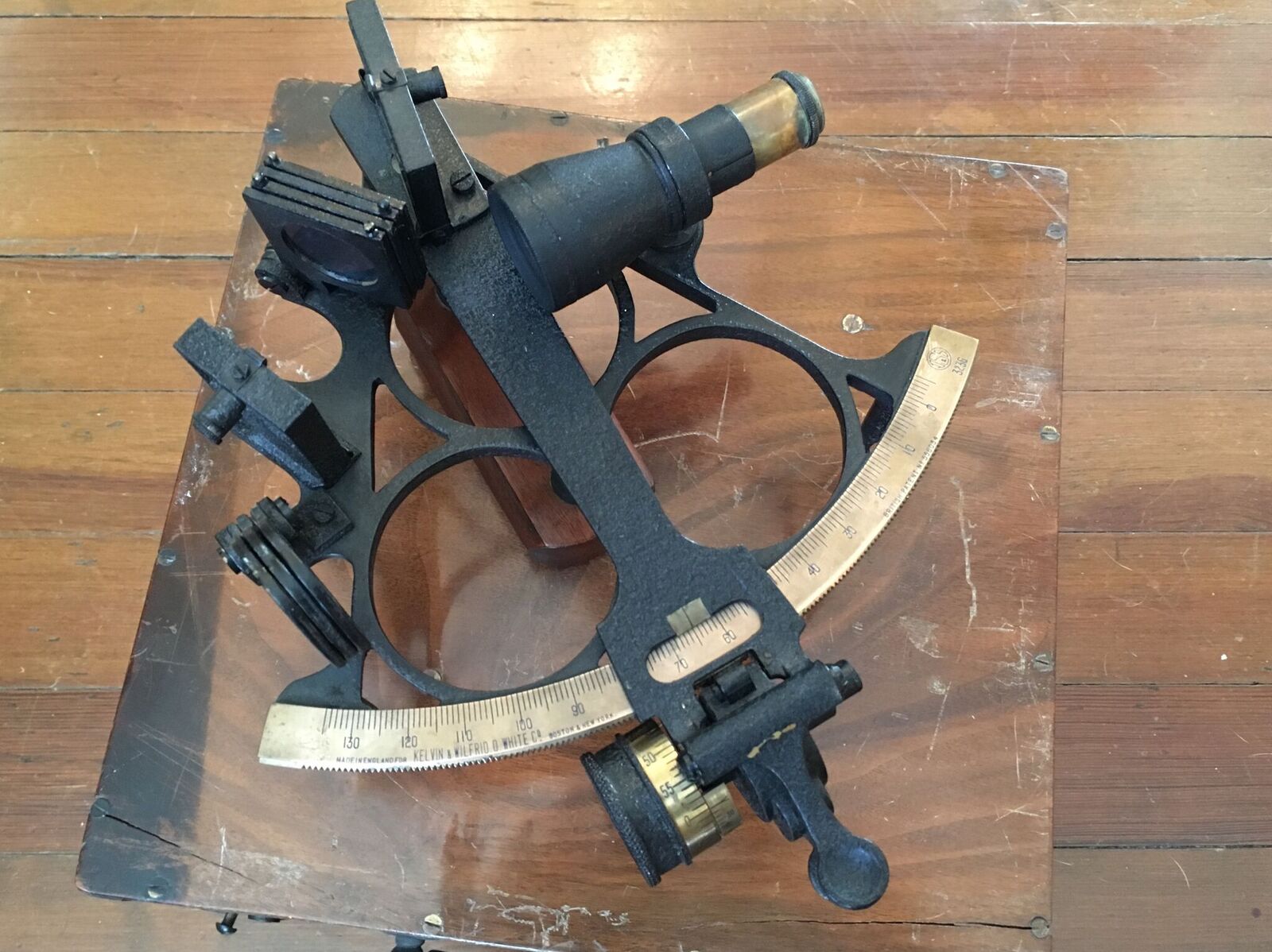
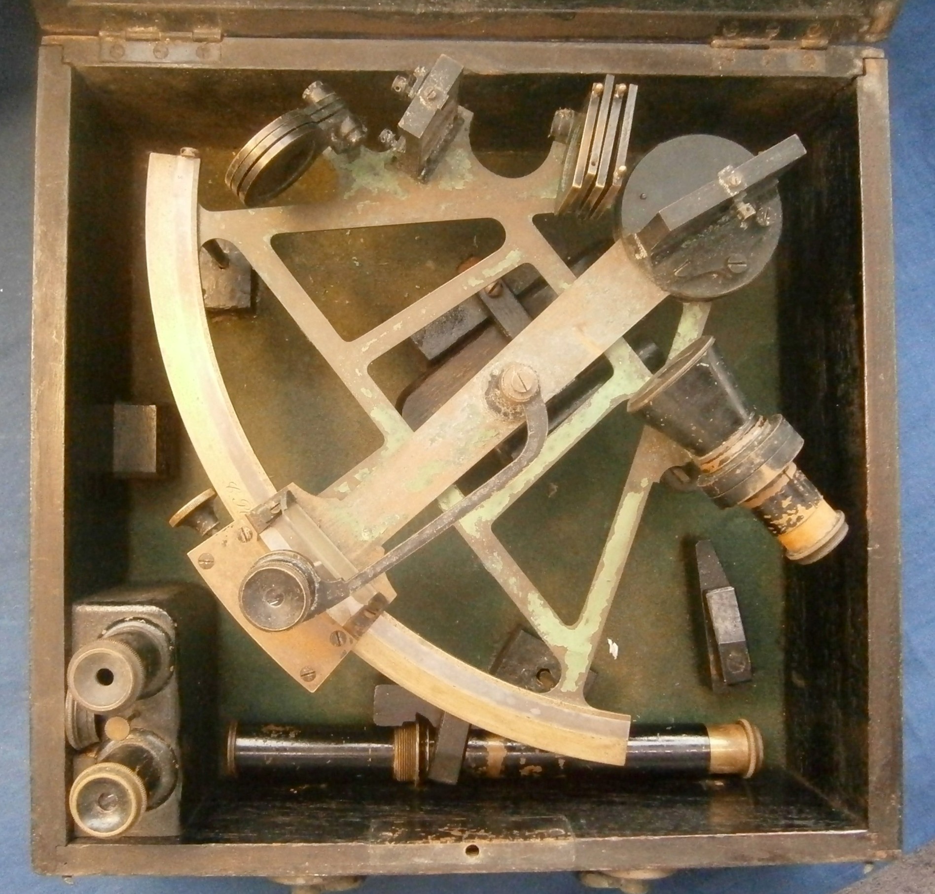
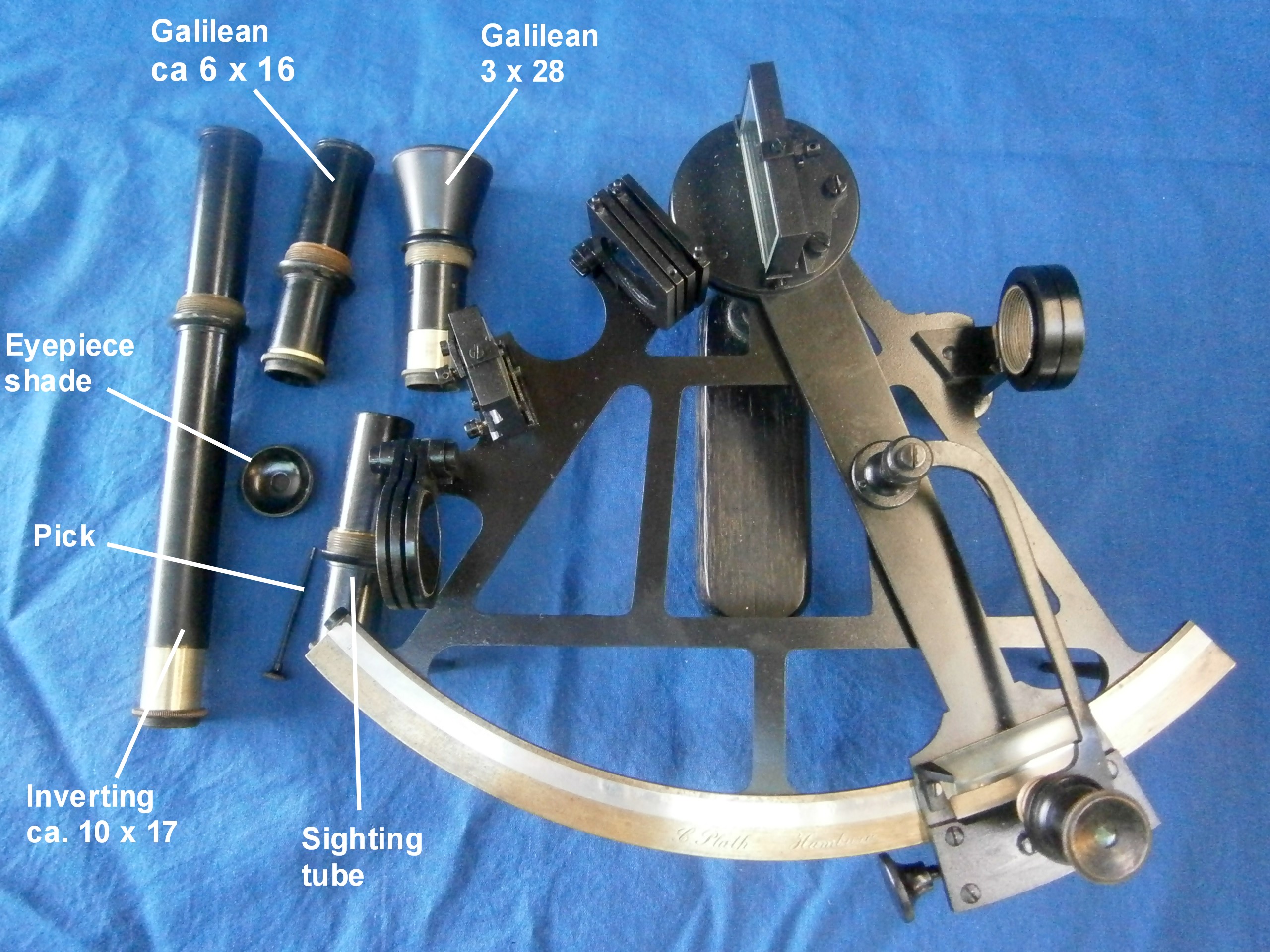
Figure 5 shows the octant in its case with the major parts labelled for the benefit of those people who have yet to buy a copy of “The Nautical Sextant.”
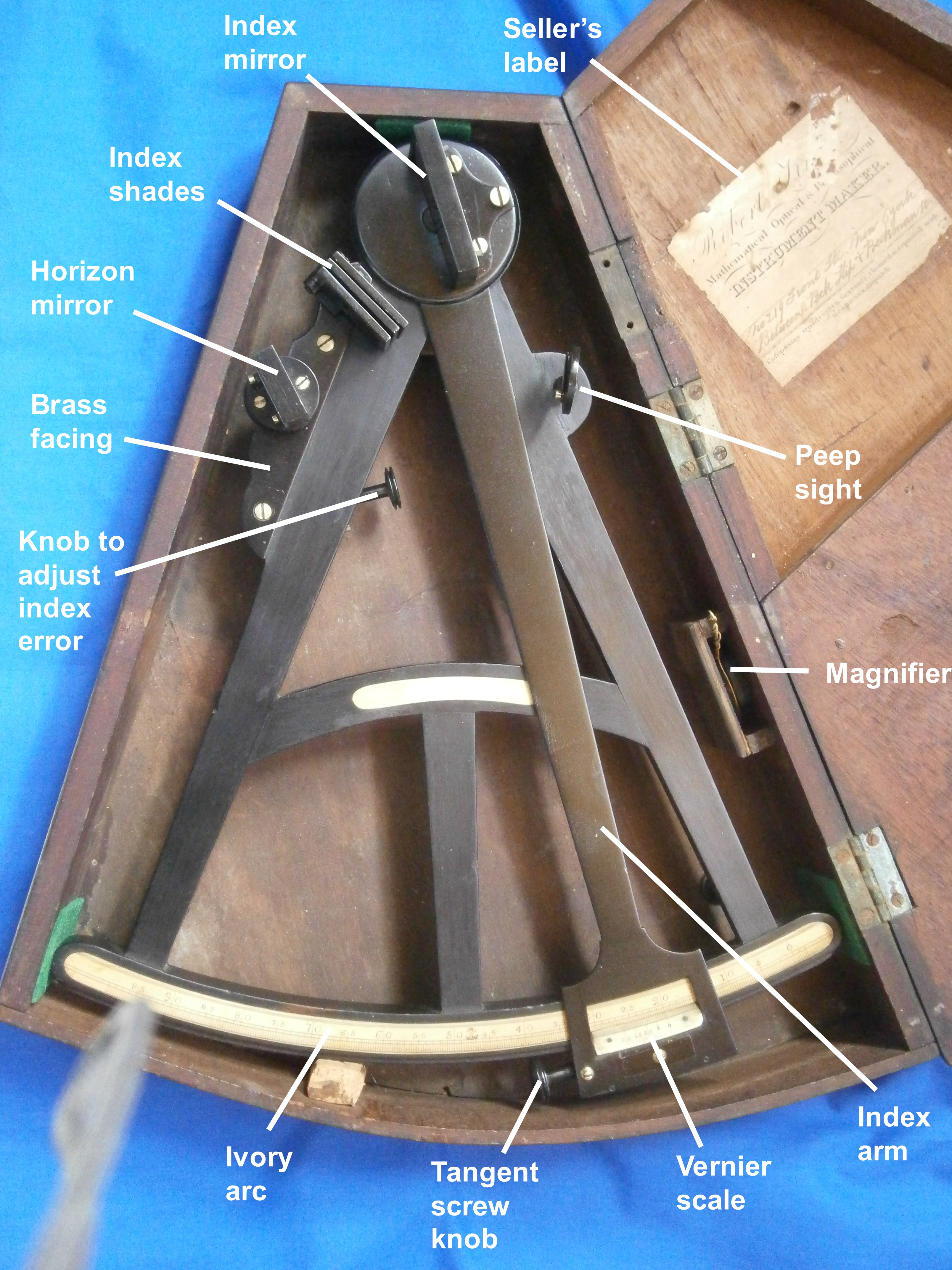
Figure 5: Octant in its case
As is usual with keystone cases, the octant is a tight fit and the curved part of the case is not, as one might expect, a segment of a circle, but its radius increases from left to right, so the index arm has to be set over to the right. I have added pieces of felt at each corner to the rectangle of cork that prevents the index arm expansion from resting against the inside of the case.
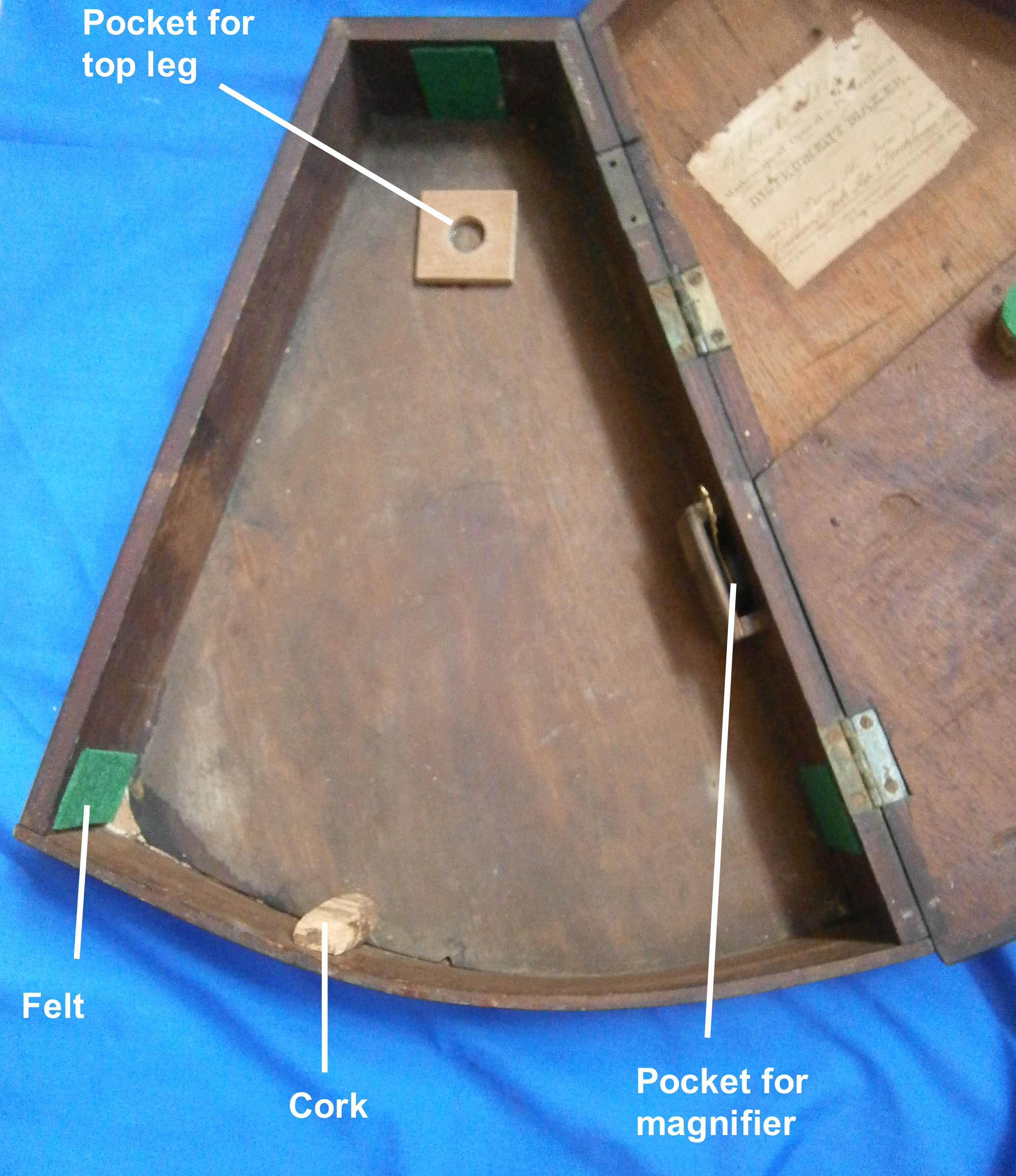
Figure 6: Interior of case.
Just visible in Figure 6 is a circular piece of cork, faced with felt, attached to the lid. This sits on top of the transverse member of the frame and, with a pocket for the top leg which I have added, prevents the octant moving about when the lid is closed.
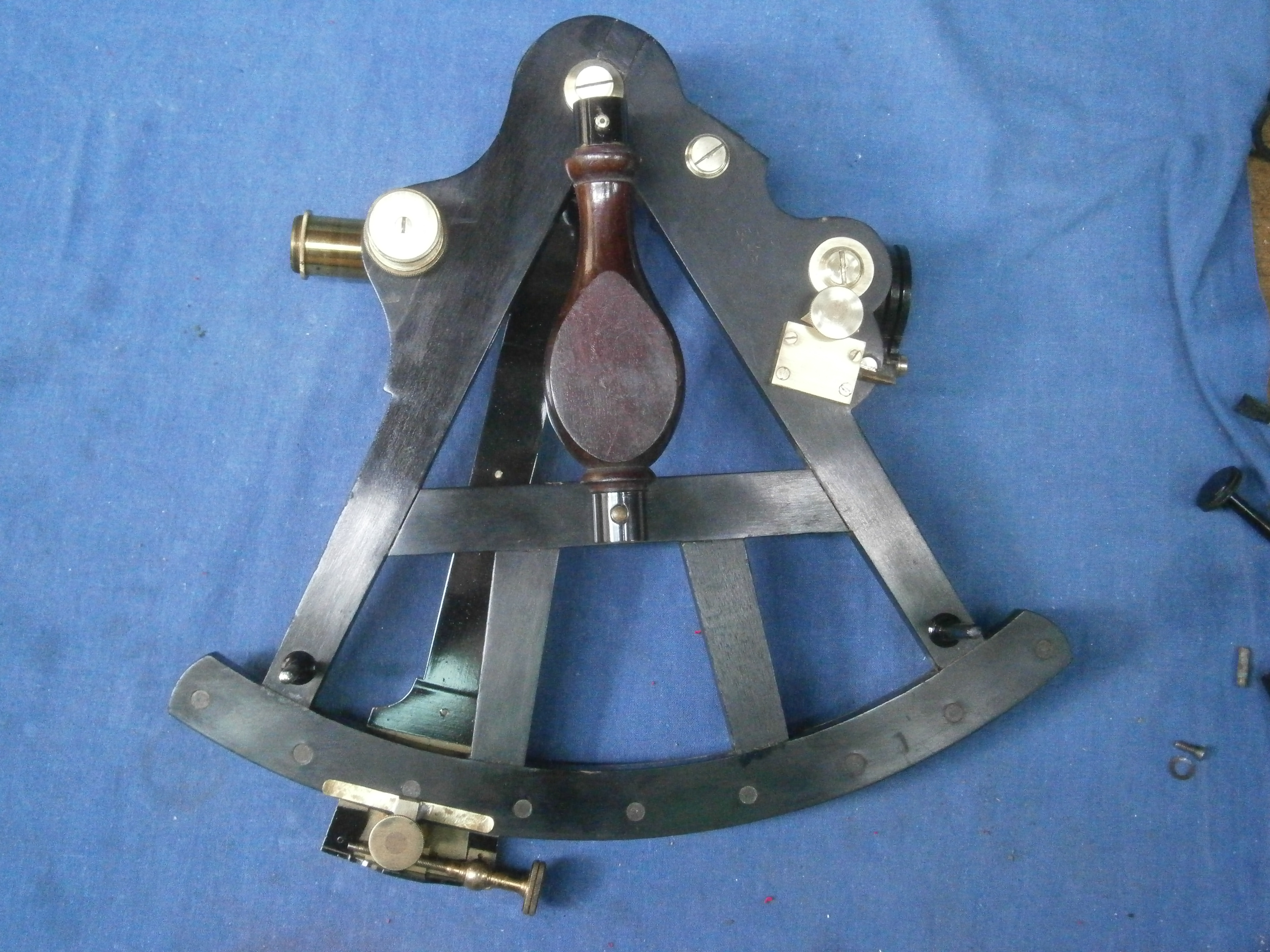
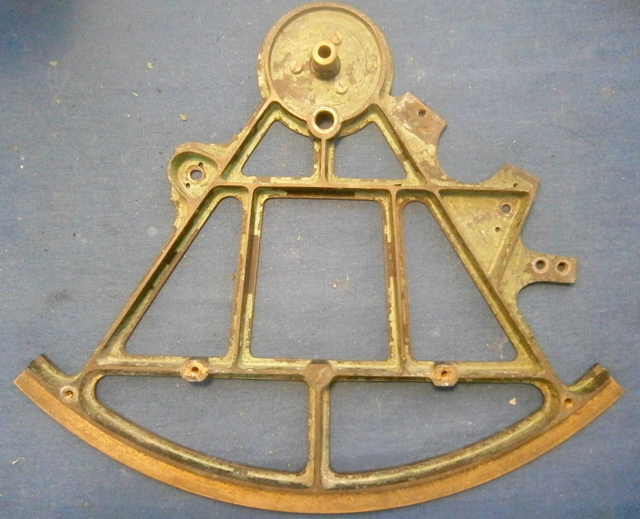
Figure 6 shows a rear view of the instrument out of its case. The frame is made of heart ebony, a hard, black, stable and very dense African hardwood. The index arm and most of the other fittings are of brass, while the arc and note pad are of ivory.
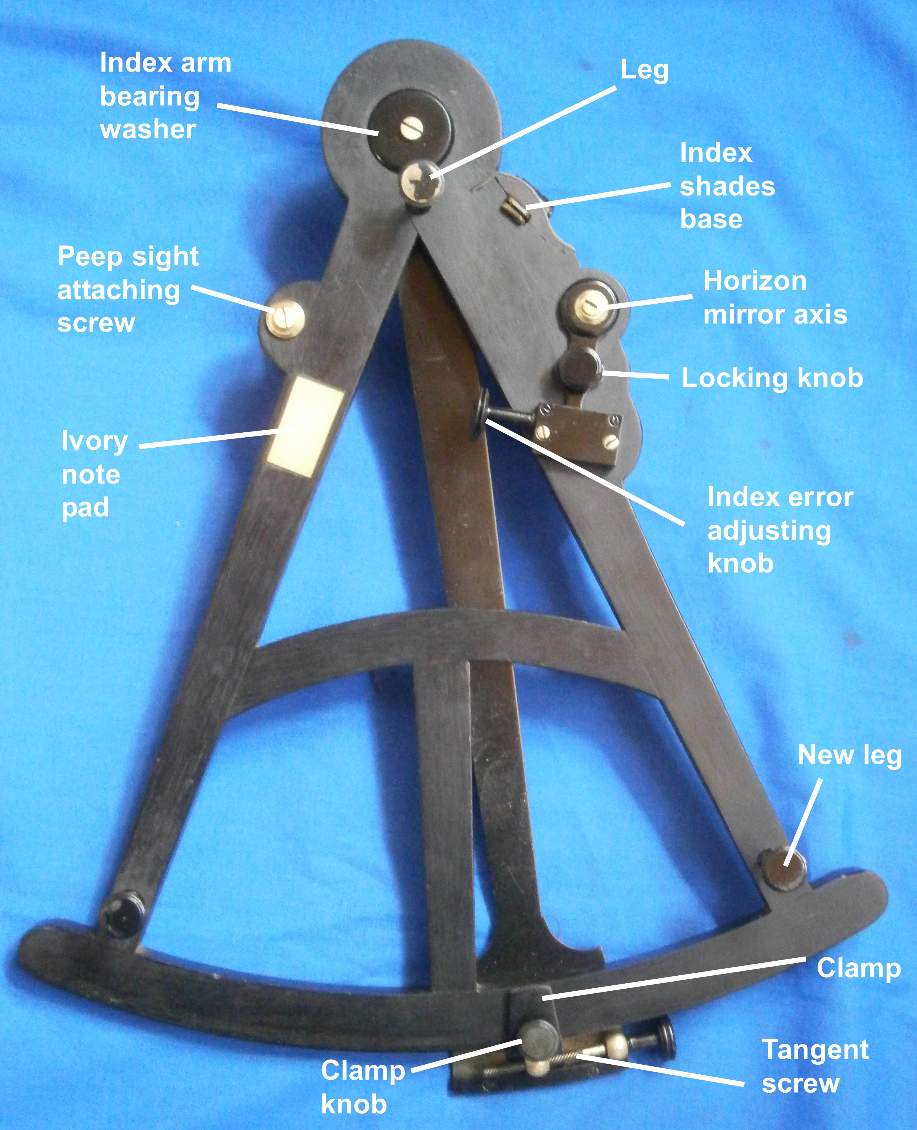
Figure 7: Rear (right hand side) view.
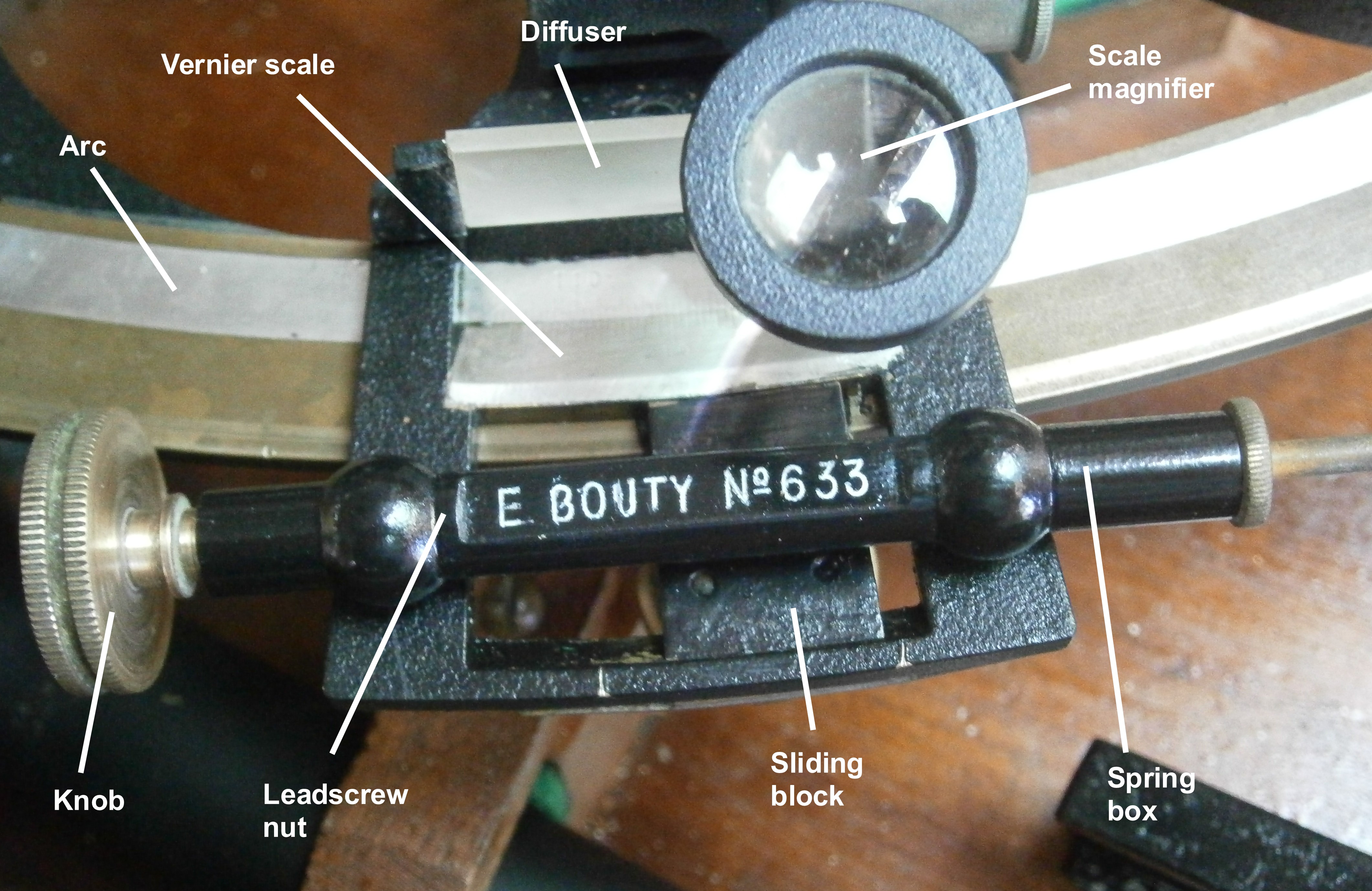
Figure 8 shows details of the scales. The main scale is divided to 20 arc-minutes and the vernier allows readings to a precision of 1 minute. The scales are very well preserved. Ivory tends to shrink in a dry atmosphere and often the glue that holds the main scale inlaid into the limb gives way at one end. The vernier is as usual riveted to the index arm and shrinkage often causes the ivory to crack around one of the holes.
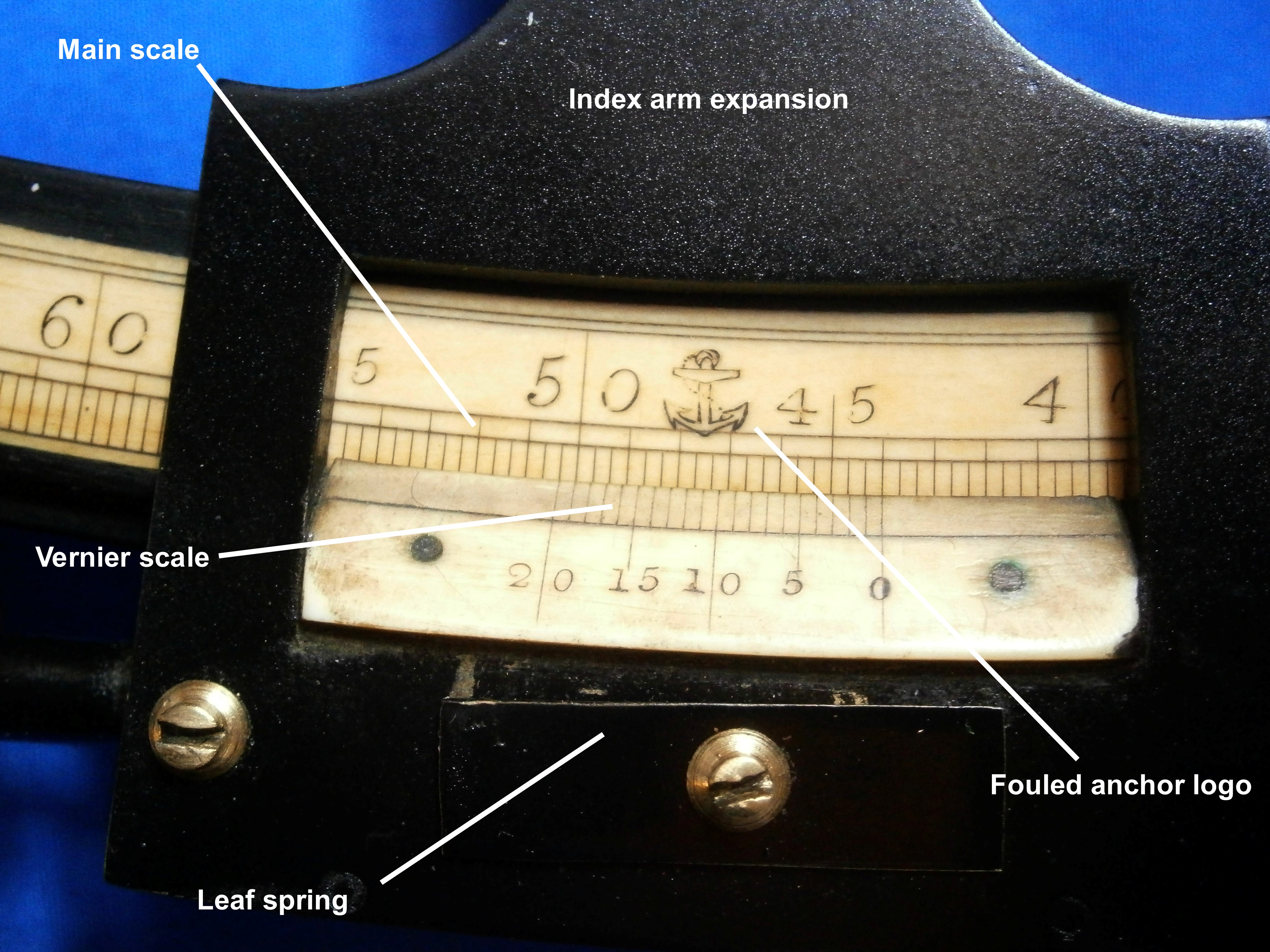
Figure 8: Details of scales.
When wooden frames gave way to ones of bronze, ivory for the scales continued to be used in cheap instruments, rather than scribing divisions directly into a brass limb rivetted to the frame. The sextant described in my post for September 17, 2018 is the only one I have seen where this has been done. Usually, an arc of silver was let into the limb, as the pure silver was unlikely to divert the scriber like the hard spots often found in the brass of the era.
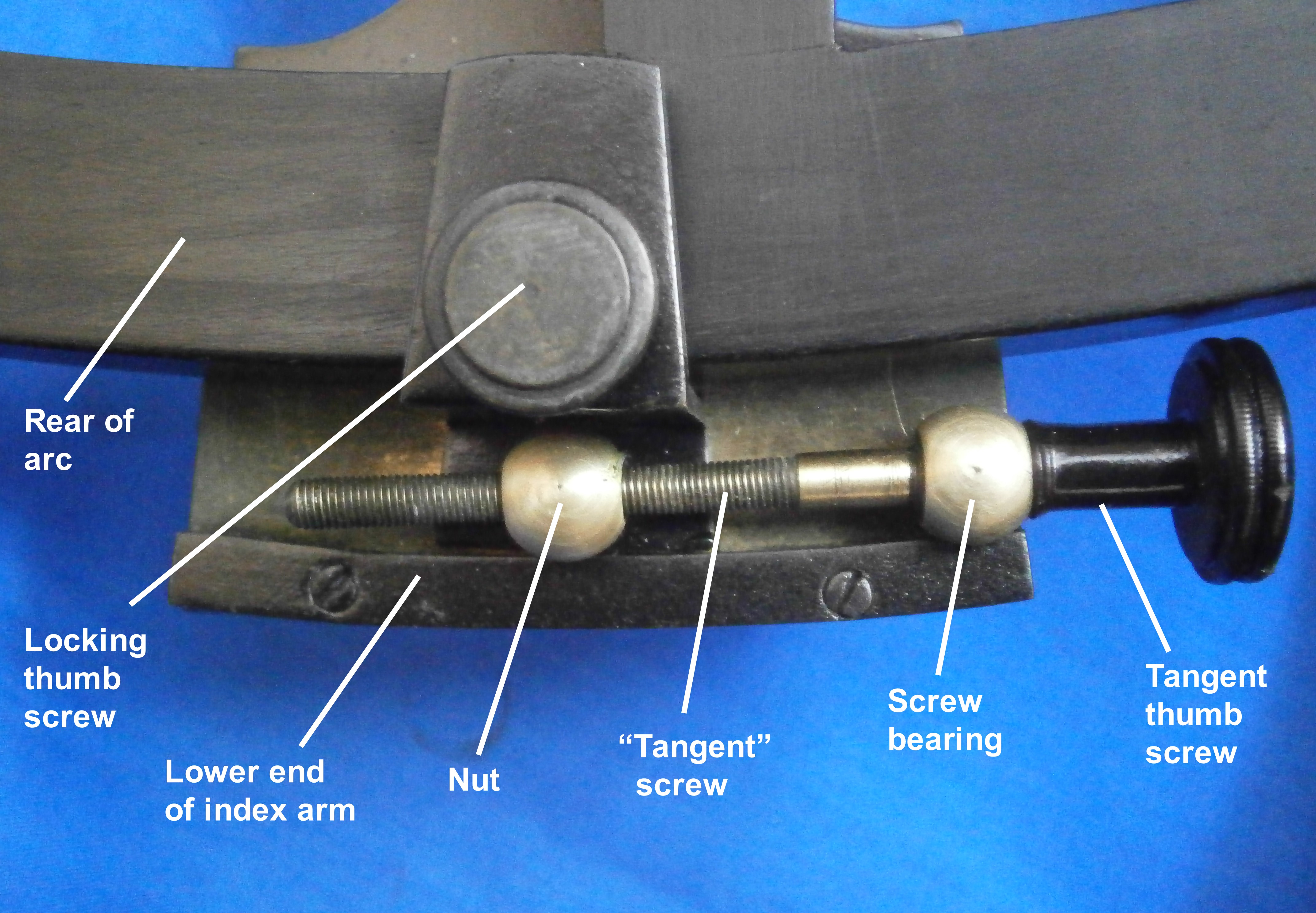
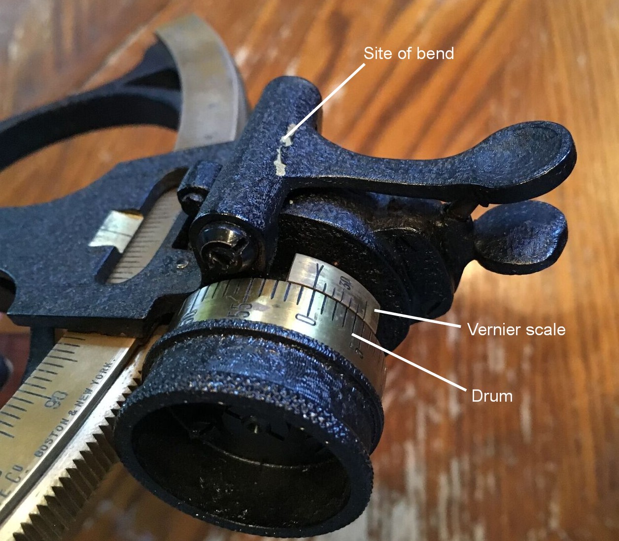
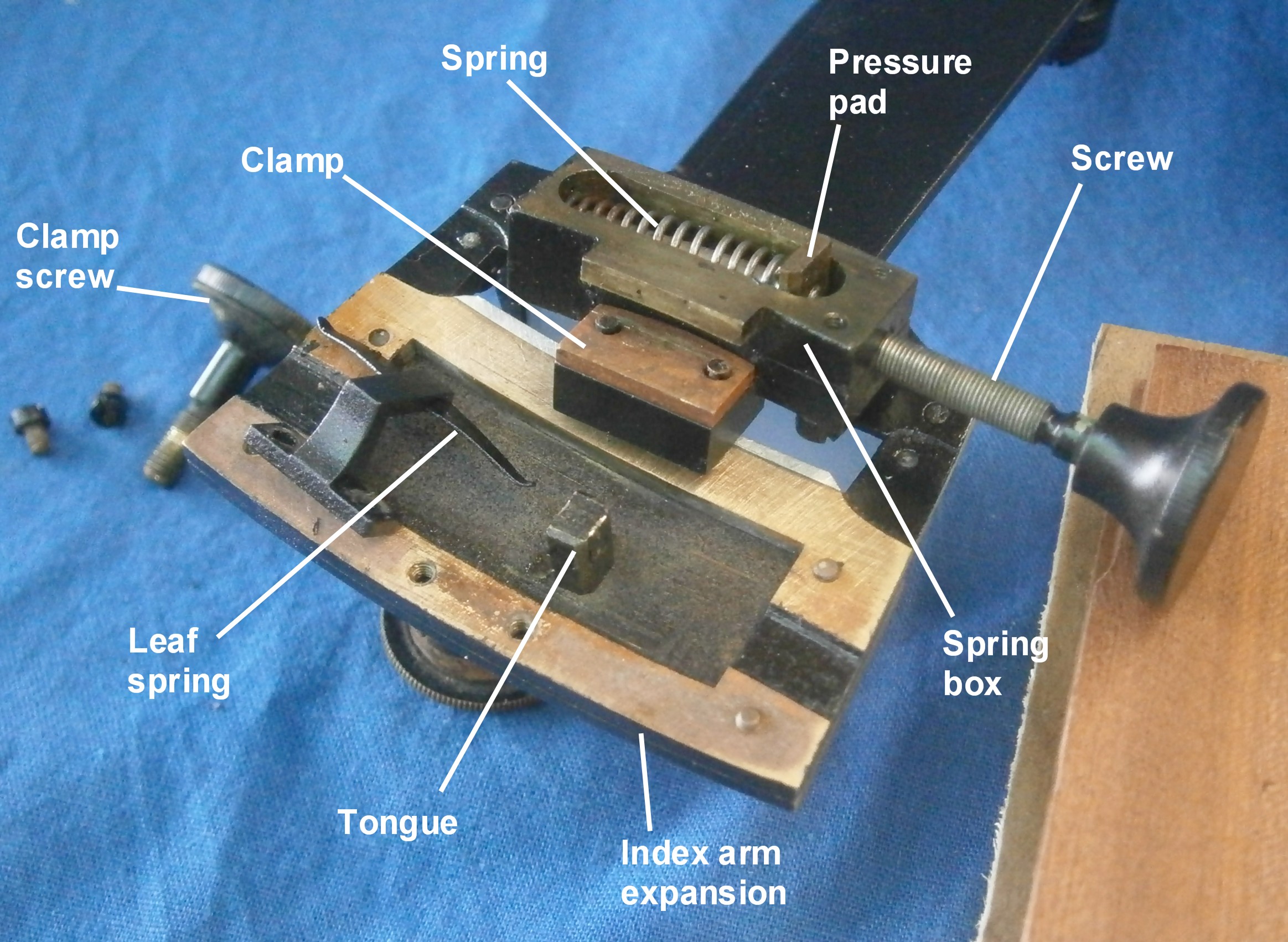
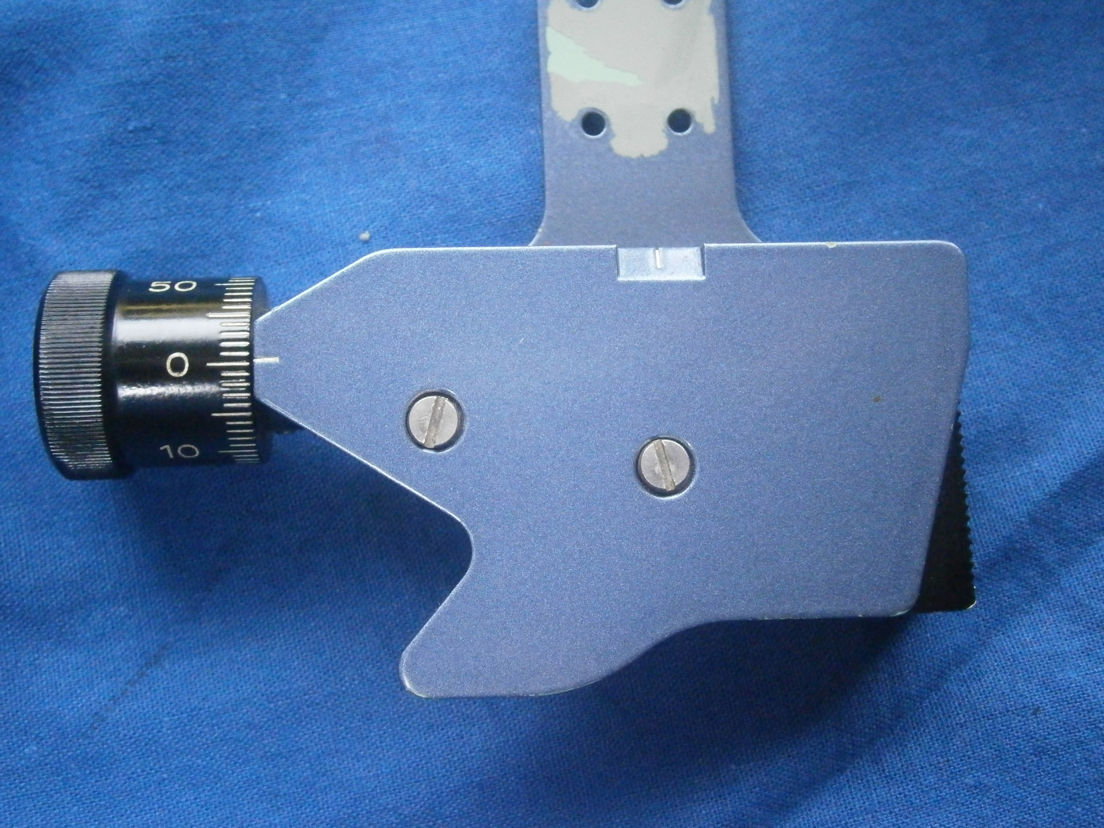
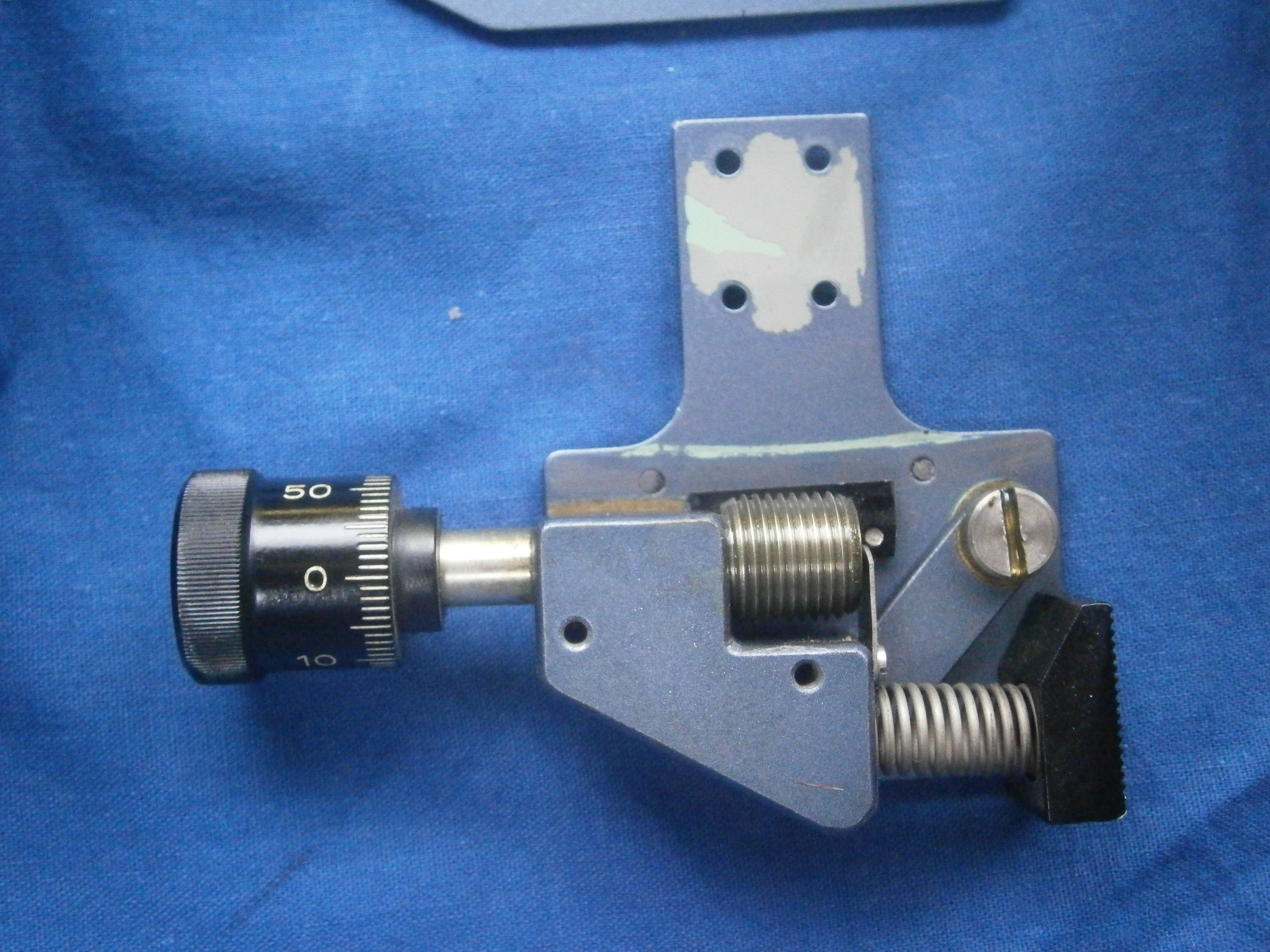
Figure 9: Tangent screw details.
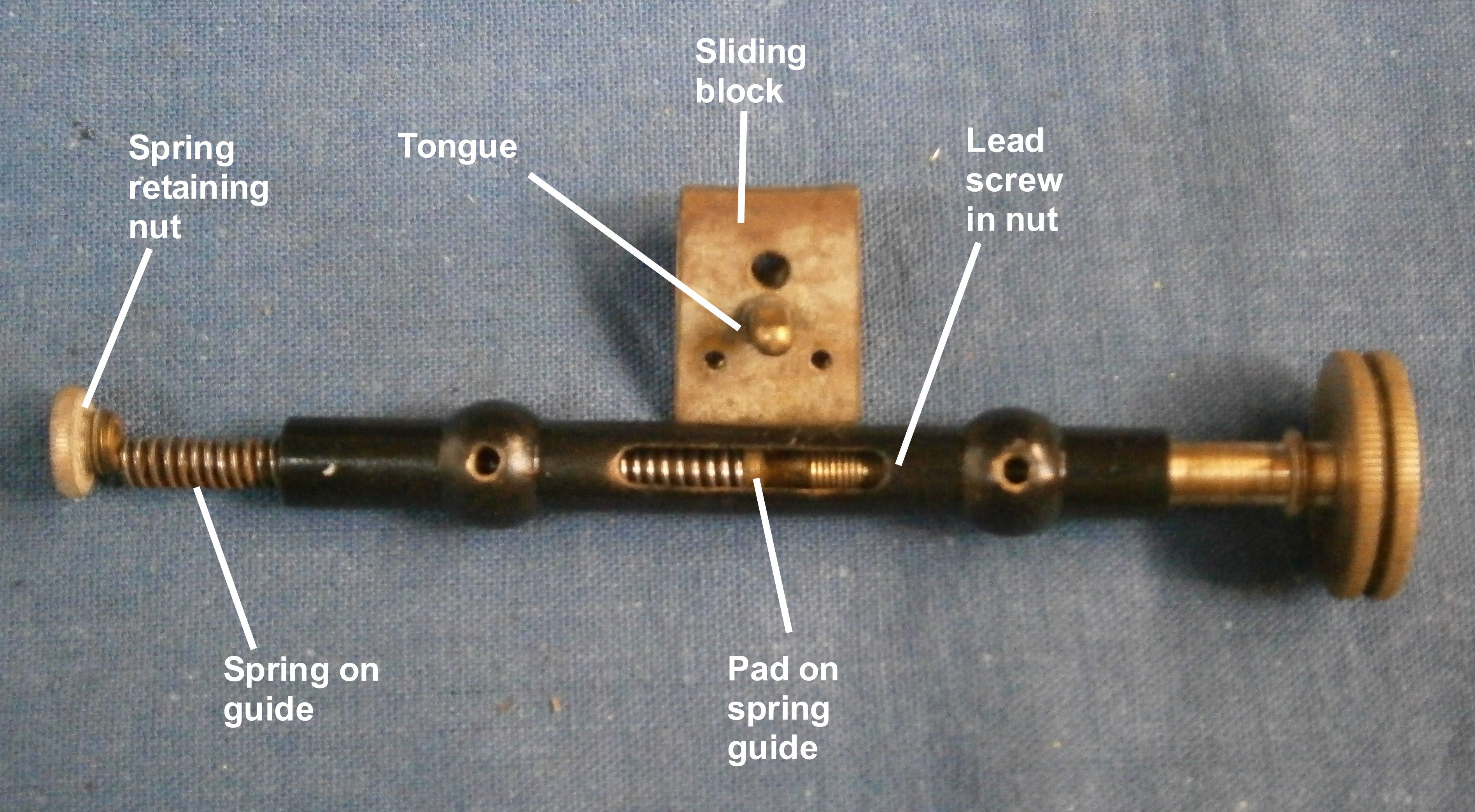
The mechanism for fine adjustment of the index arm is shown in Figure 9. Releasing the “clamp” by unscrewing the locking thumb screw allows the index arm to move freely so that a body can rapidly be brought down to near the horizon. Then the Z-shaped piece of metal shown here and in Figure 10 is clamped to the limb. The nut is also attached to this piece of metal or “clamp”. The tangent screw is held captive in its bearing on the right of Figure 9 and the bearing is attached to the index arm, so that when the screw is rotated the index arm is moved slowly one way or the other about a curved guide formed for the base of the clamp on the back of the index arm.
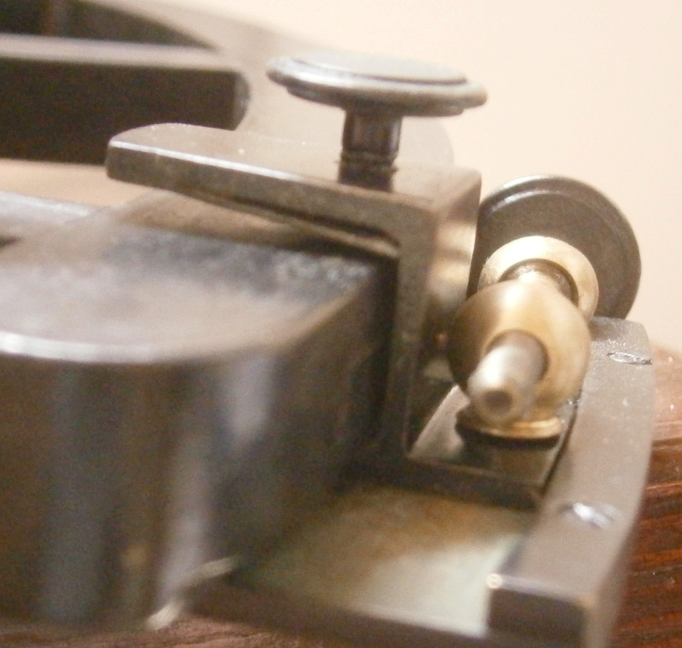
Figure 10: End view of tangent screw clamp.
A piece of spring steel protects the back of the limb from the tip of the clamp screw. What is difficult to show in either photo is that there is a short tongue projecting at the base of the “Z” and this slides in a rebate on the front of the limb – except when the clamp screw is tightened.
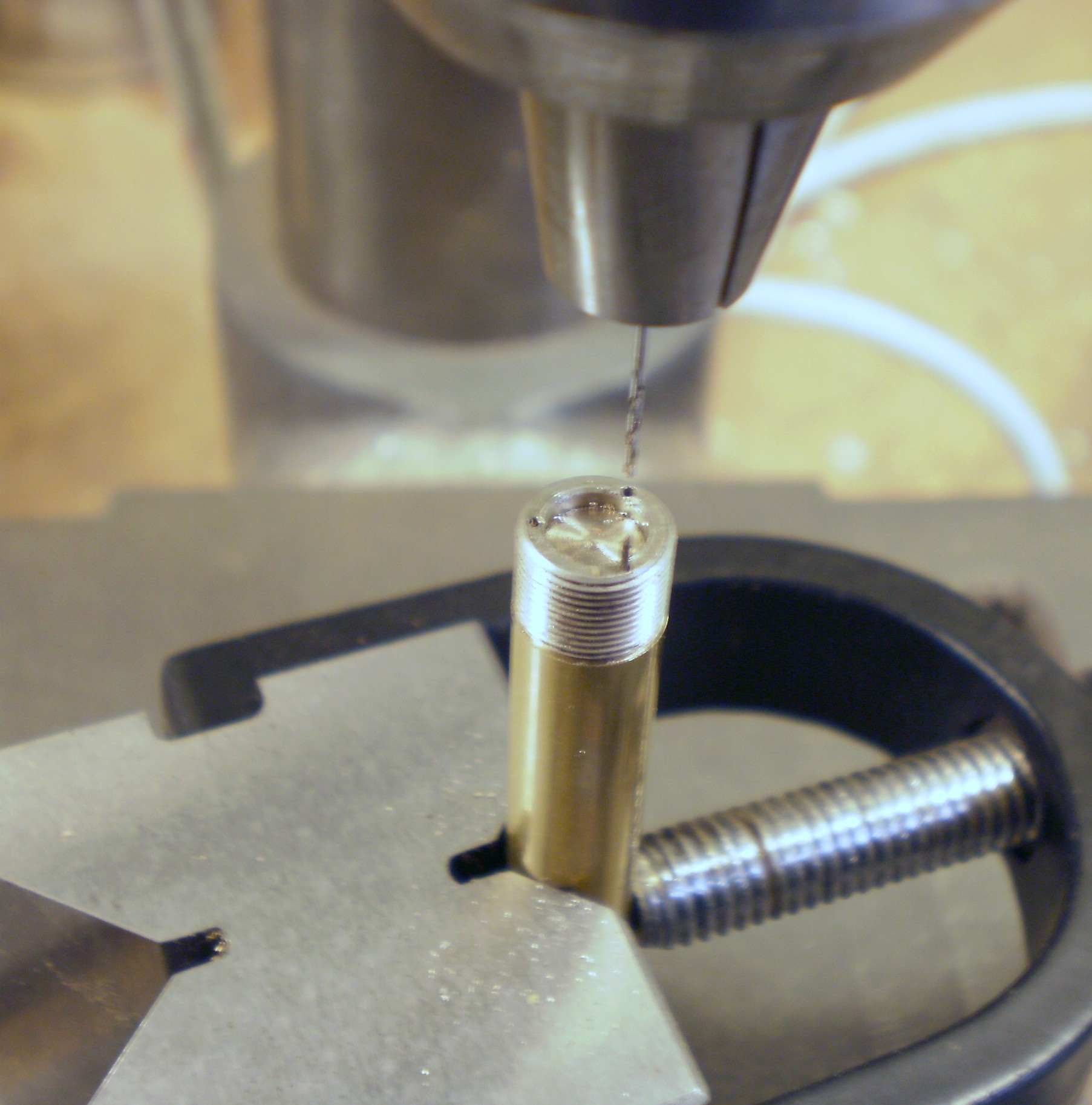
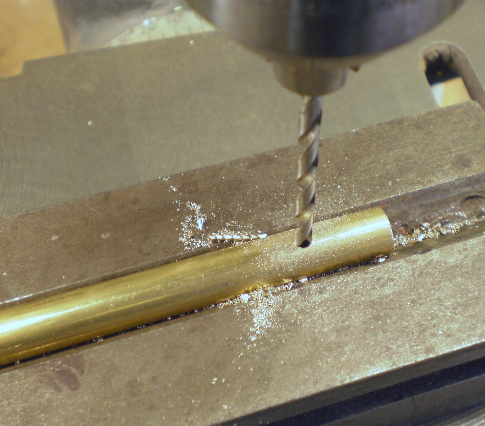
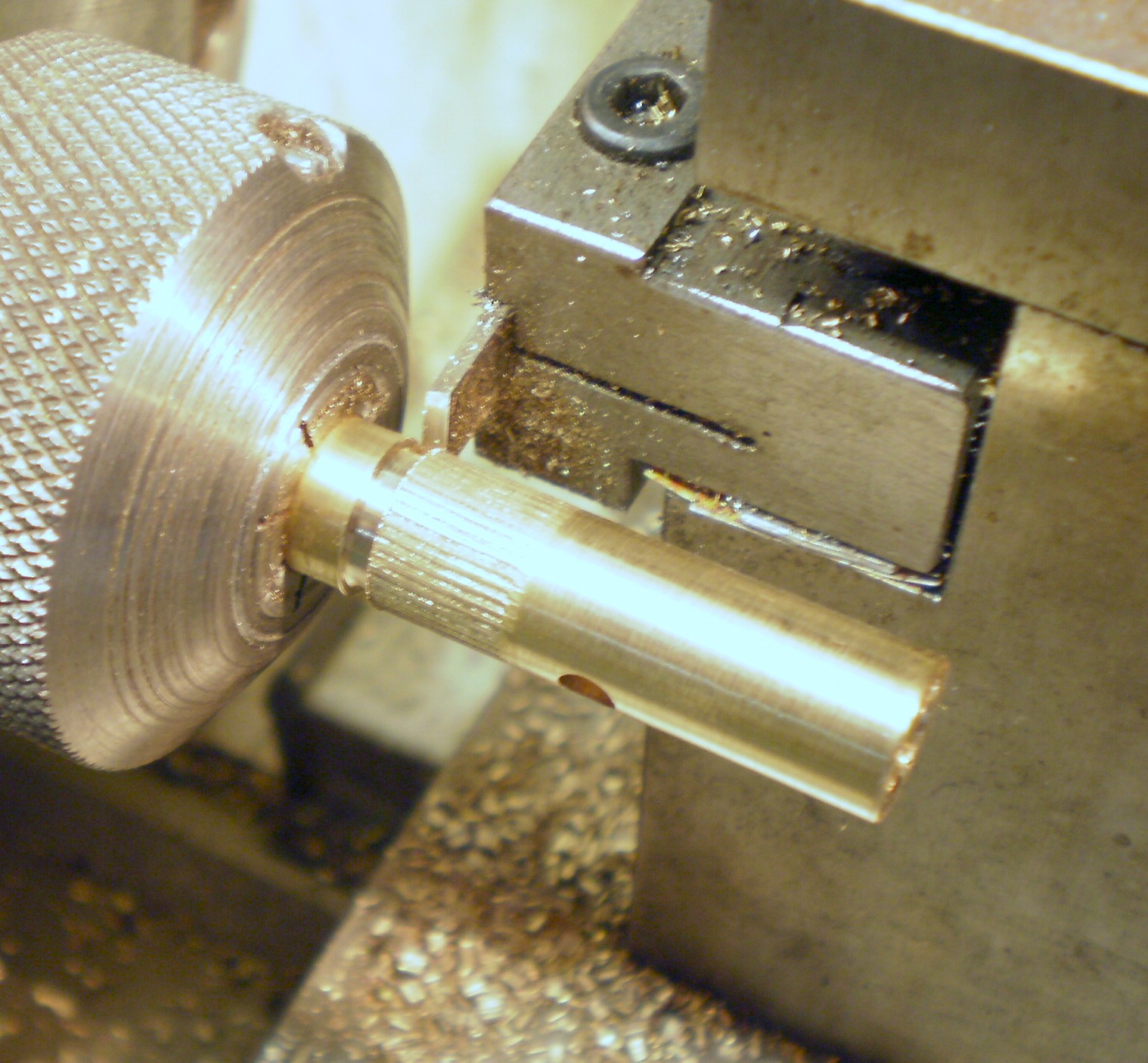
As the peep sight was missing altogether, I had to use the pillar from another sextant as a guide to its shape, and then saw and file up the shape of the disc part from sheet brass. I then inserted the disc into a mortice machined into the top of the pillar and secured it with solder.
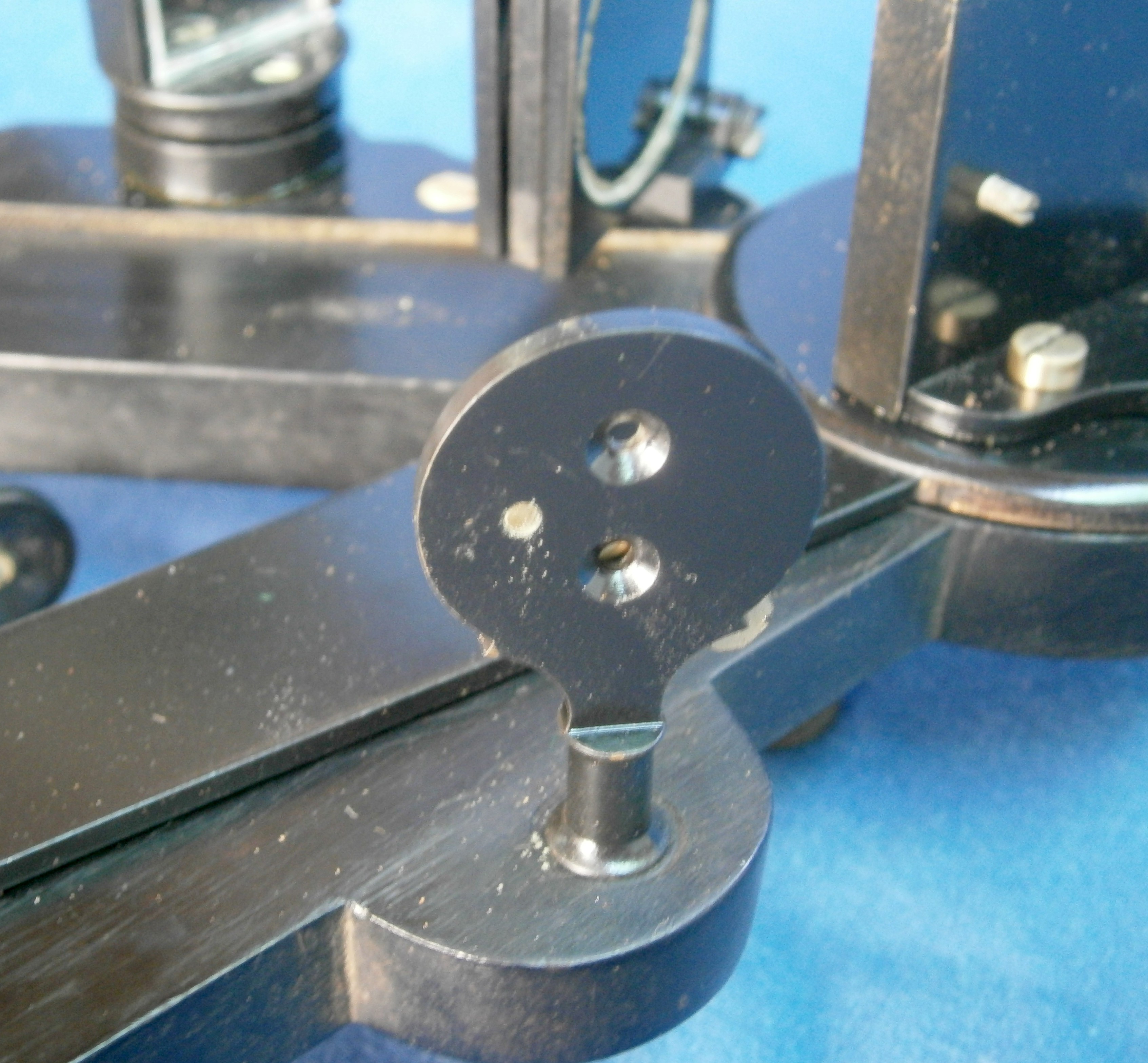
Figure 11: Peep sight from eye side.
The centre line of the two holes lines up with the horizontal centre line of the horizon mirror. The hole nearer the frame lines up with the junction of the plain and silvered parts of the mirror, while the other hole allows a larger view of the horizon for when its contrast is poor. The shade shown in Figure 12 can be rotated to obscure one or the other of the holes.
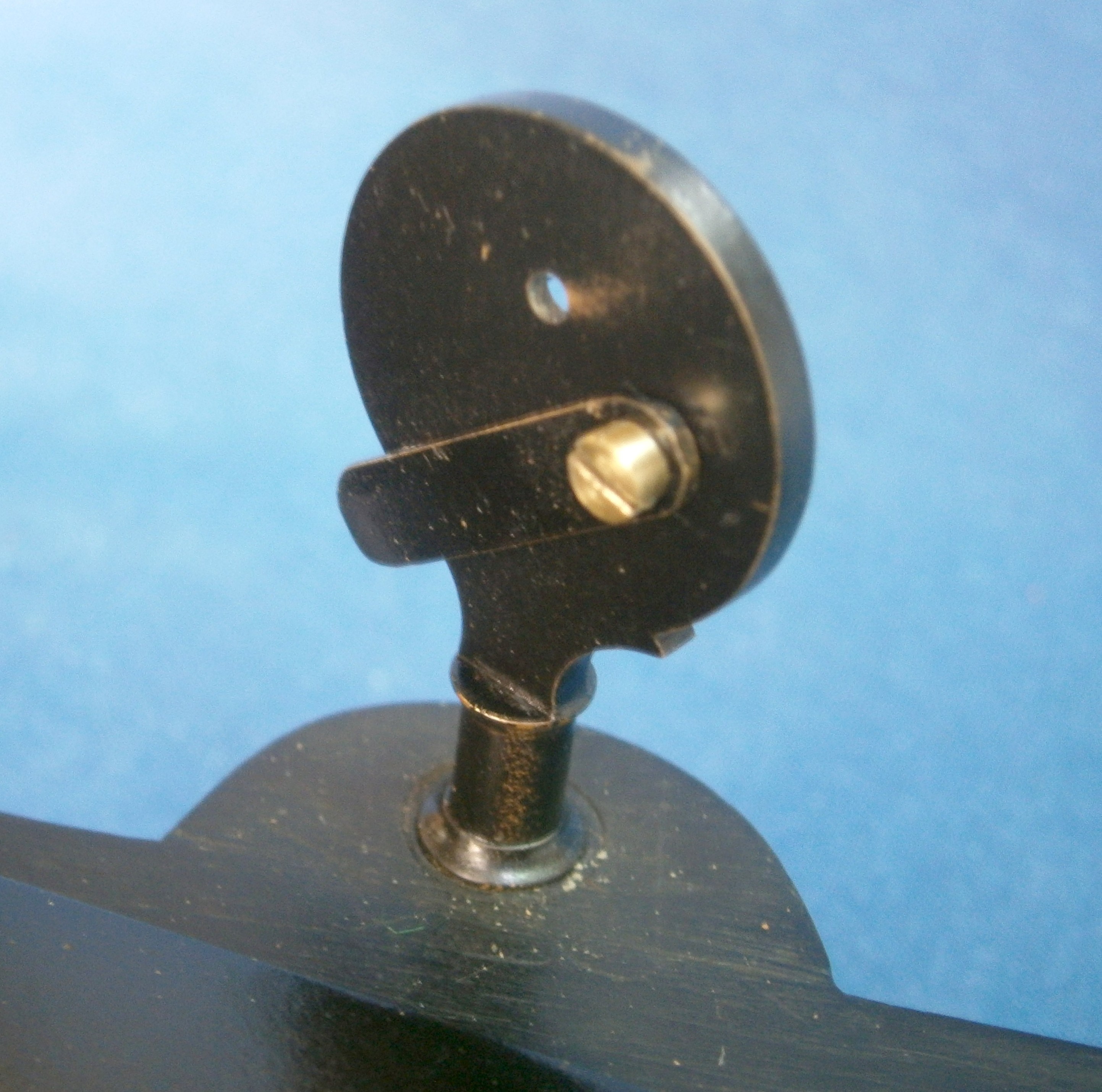
Figure 12: Rear of peep sight.
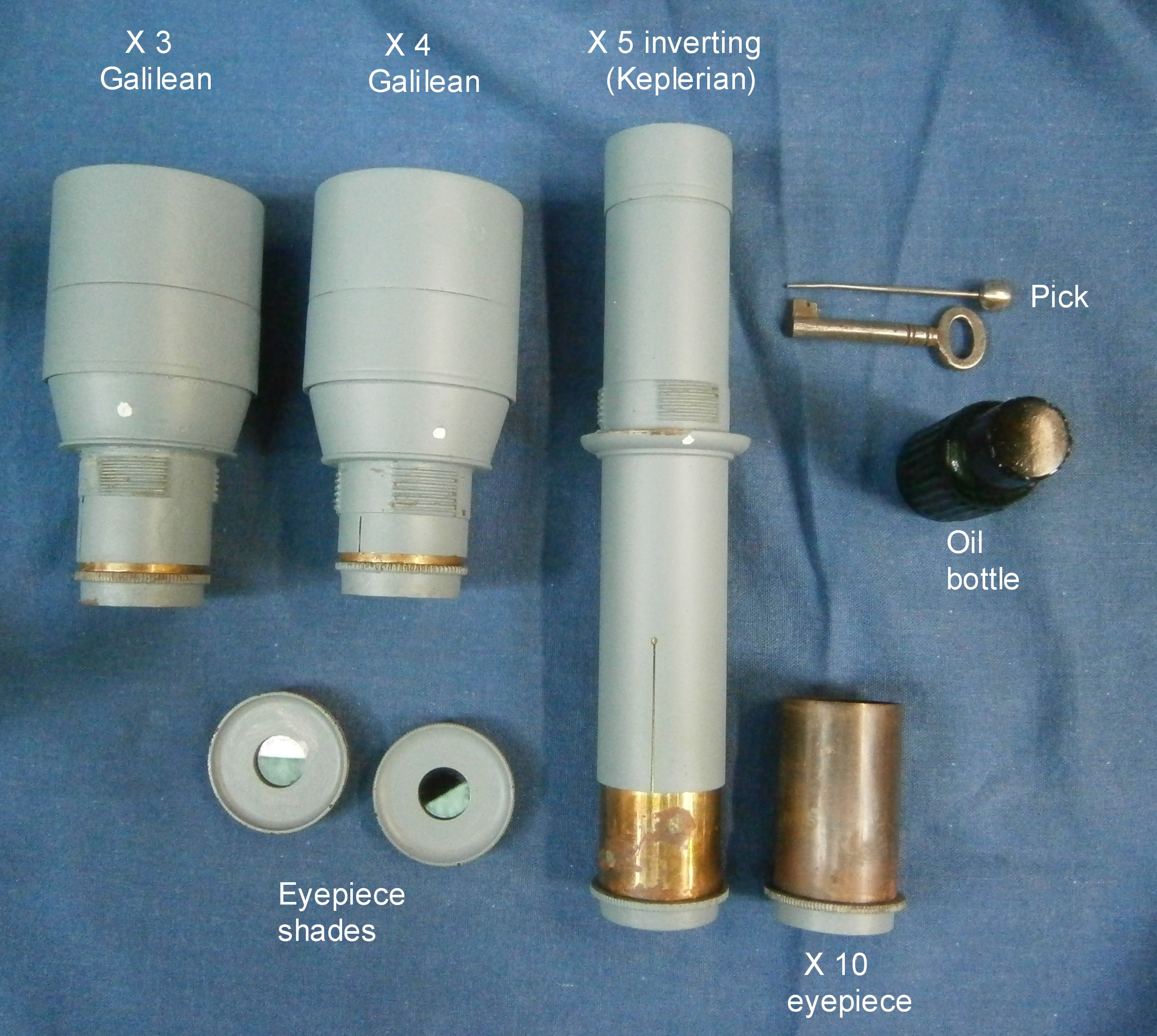
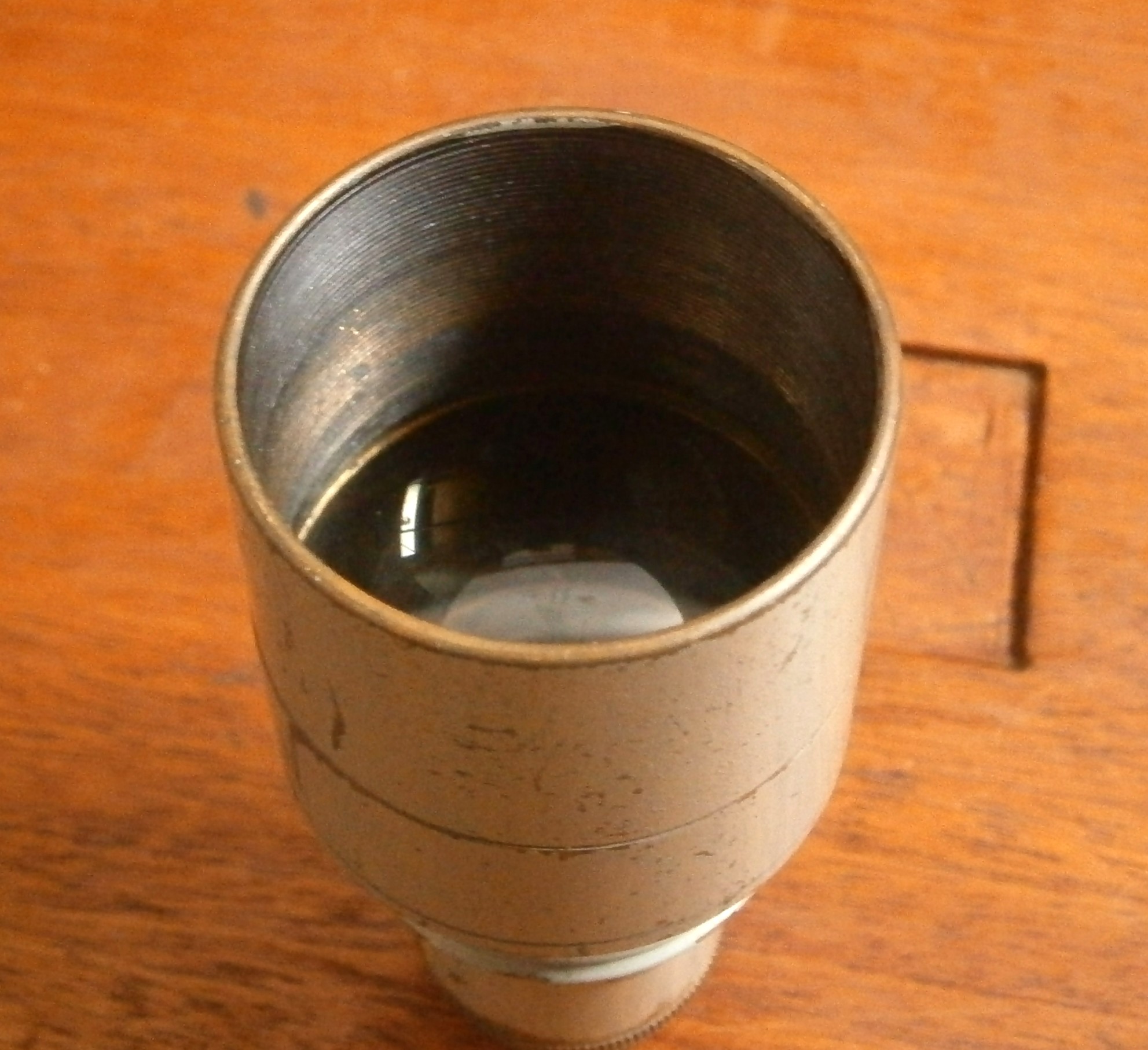
Flint glass was essential to make achromatic lenses, but in the eighteenth century it was difficult to obtain in large pieces, so that telescopes were not only expensive but had relatively small apertures of 16 to 20 mm.
When a sextant or octant was used only for taking the noon altitude of the sun for latitude, a peep sight was perfectly adequate for a “normal” eye, which could resolve an arc-minute, in keeping with the precision of the instrument. A normal eye is usually quoted as 6/6 vision (20/20 in the USA), but many young people have 6/4 vision or even better, meaning they can resolve detail at 6 metres that a “normal” has to be at 4 metres to resolve.
When it became necessary to resolve 10 arc seconds (one sixth of a minute) in order to measure lunar distances between the moon and the sun or stars, telescopes became nearly essential, though that great navigator, humanitarian and scientist, Captain James Cook, did not use one until his second voyage of exploration. On January 15th, 1773, he wrote in his log “…we can certainly observe with greater accuracy with the telescope when the ship is sufficiently steady which however very seldom happens, so that most observations at sea are made without…” With the wider field of view available with a good modern telescope it is easier to use one, but on my voyages aboard HMB Endeavour, which rolls a lot, I usually brought down a body without the telescope and then added the telescope to my modern sextant to make the fine adjustment and bring the body to sit accurately on the horizon.
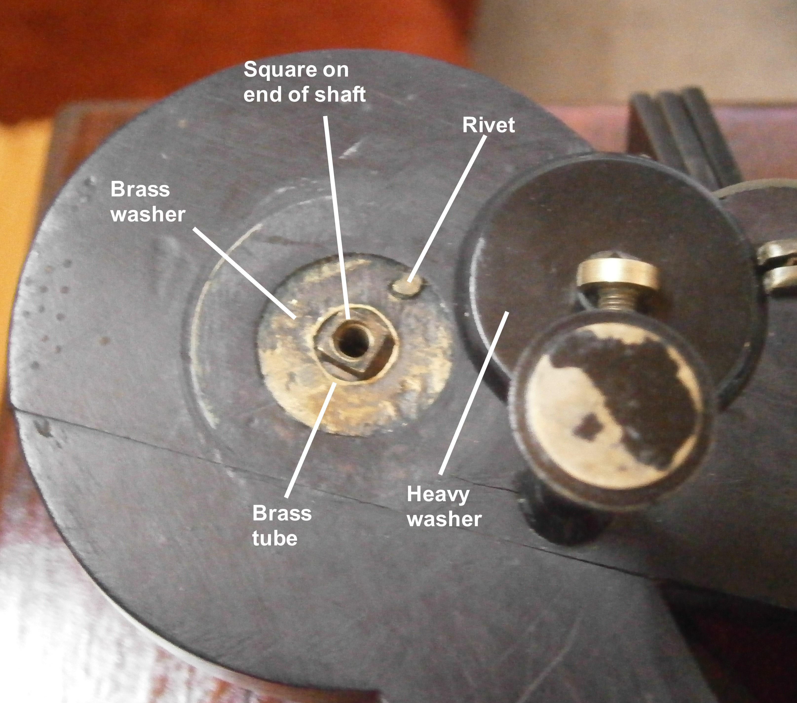
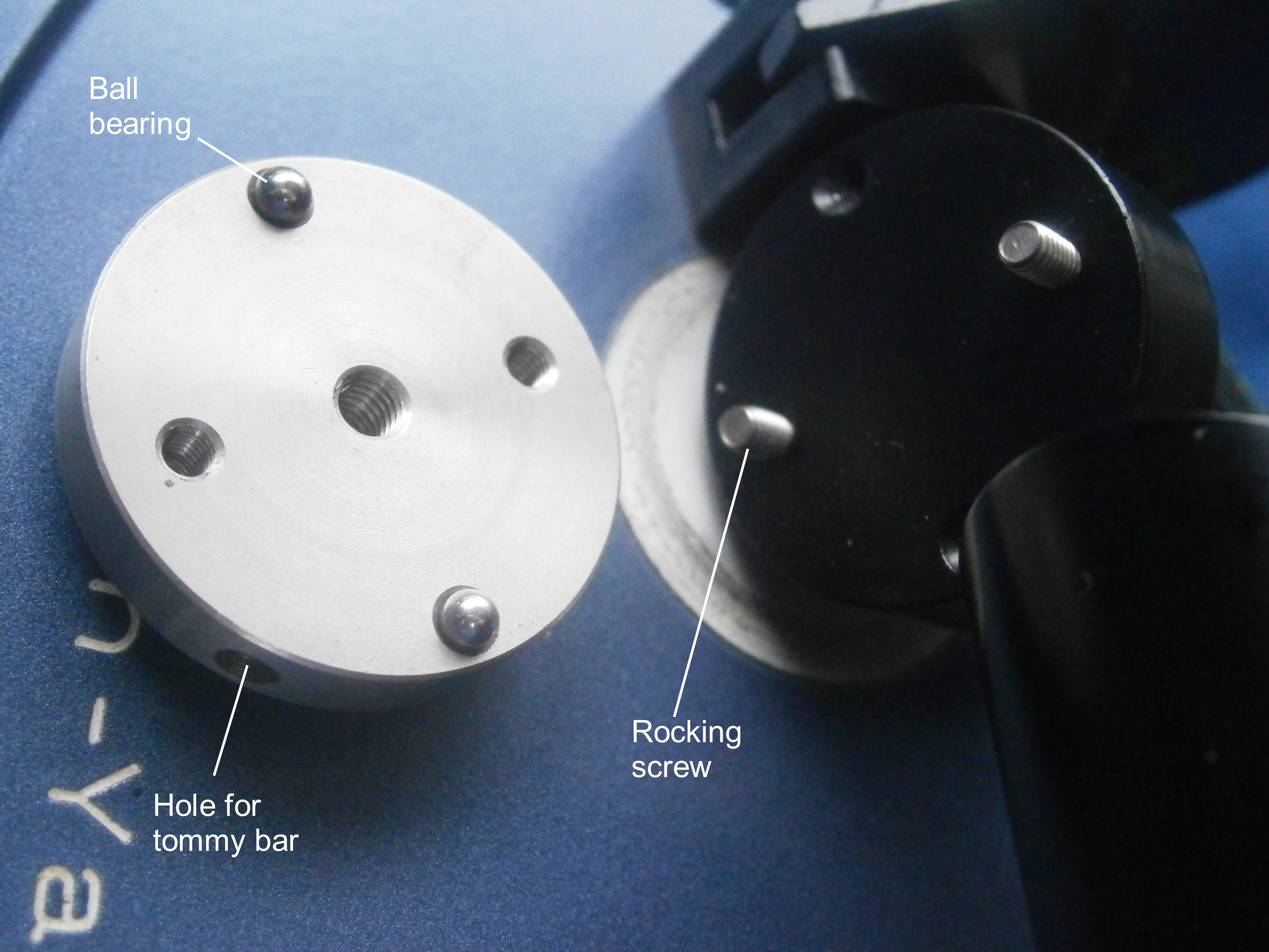
Figure 13: Structure of index bearing.
Figure 13 shows the structure of the index bearing. Strictly speaking, it is that which encloses the journal or shaft, but loosely the word is used to include both. There is a brass washer let into each side of the frame and the two are held together by two rivets. The washers enclose a short piece of brass tubing, which forms a bearing for a plain parallel shaft attached to a large circular table on the front (left) side of the octant. This carries the index mirror. Originally, a piece of parchment separated the table from the frame. As it had fallen apart, I replaced it with a thin sheet of nylon.
On the back or right hand side a heavy brass washer with a a square hole fits closely over the square on the end of the shaft, so that it turns with the shaft without rotary motion being transmitted to the securing screw and loosening it. There is no provision for taking up wear, but as it is not an instrument of the highest precision and the shaft is lightly loaded and always moves slowly, no wear is to be expected. An old author (I forget which) made reference to what we would now call “stick-slip” or “stiction” and suggested that having achieved contact of a body with the horizon and clamped the index arm, it might continue to move a little without the tangent screw having been touched. I have never been able to observe this. It may be that the author had over-tightened the bearing.
With further development of octants and sextants, a tapered bearing was adopted almost universally, as it allowed for fine adjustment, though the narrow adjusting screw was prone to be over-tightened and broken off by heavy-handed mariners who did not understand the bearing’s structure.
Figure 14 shows the front of the index mirror and its bracket. The “silvering” was probably made from an amalgam of tin with mercury and it was coated with protective sealing wax. While I have replaced the very badly decayed horizon mirror, I have left the index mirror in place as it is still just about usable for demonstrations. The clip that holds it to its bracket is archaic as it applies pressure to three edges of the mirror. From the middle of the eighteenth century it had been appreciated by the Dollonds that to avoid straining and distortion of the glass, it should be restrained at three points only, and seated under these points on three nipples.
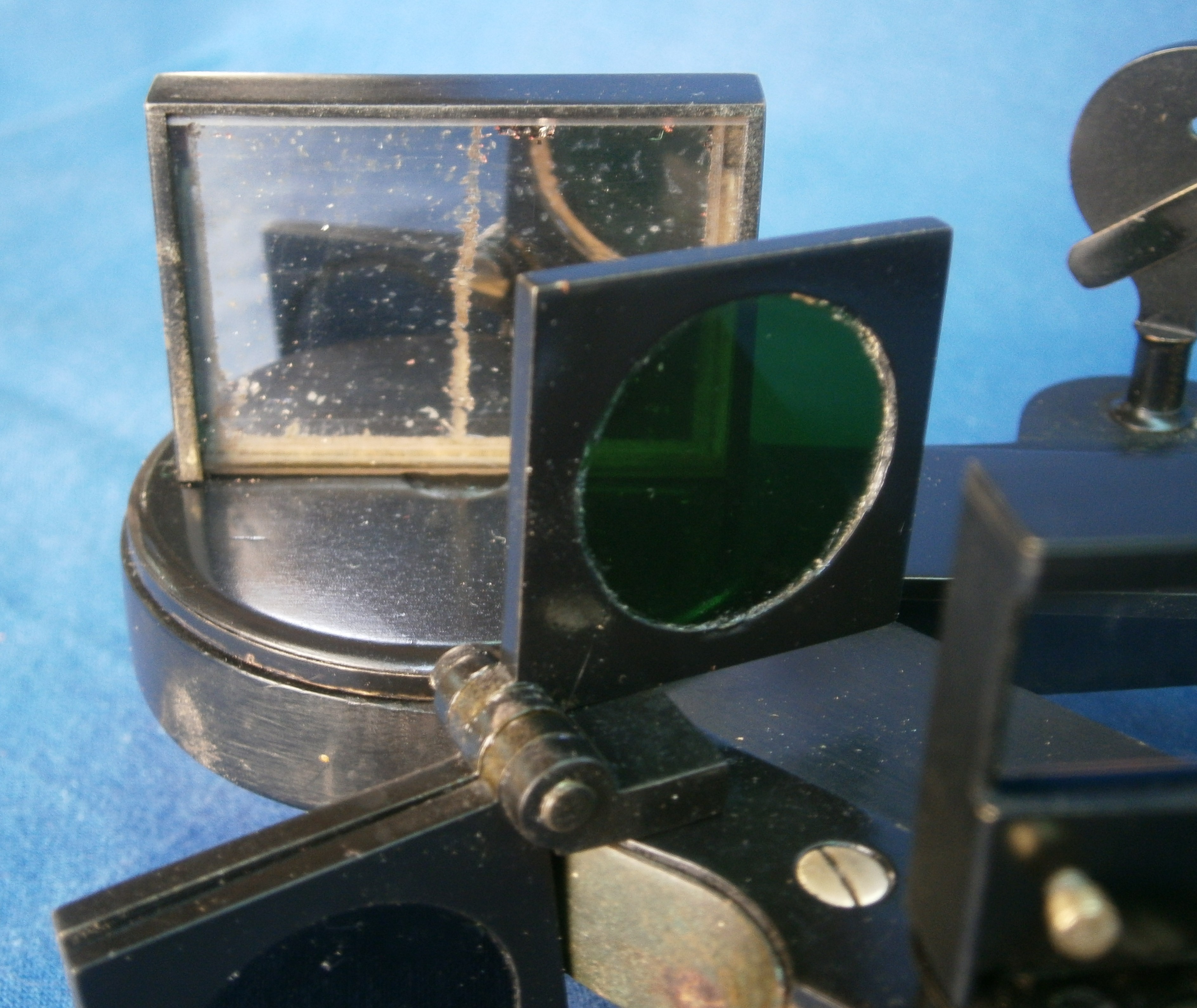
Figure 14: Front of index mirror and bracket.
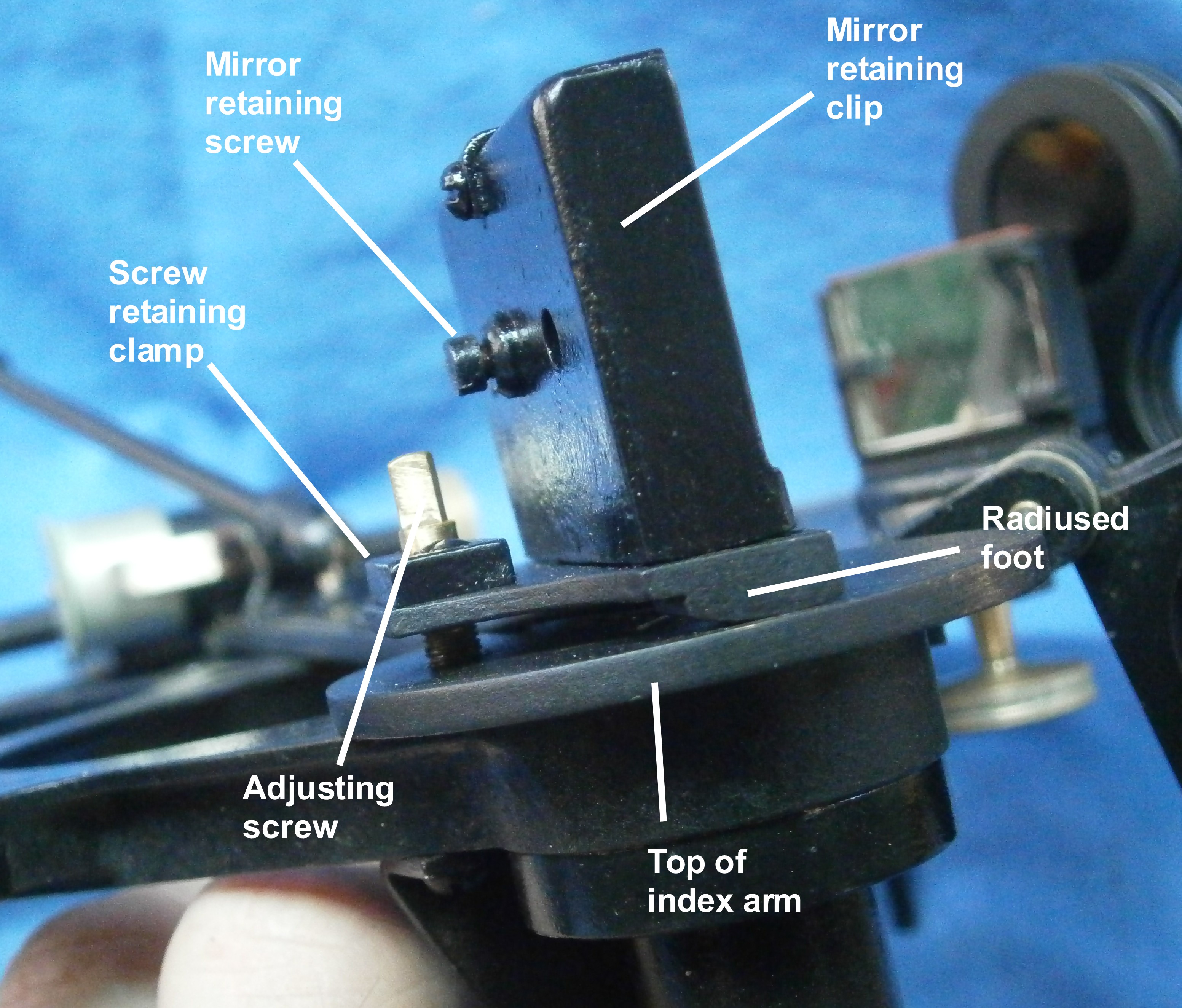
The rear of the clip (Figure 15) has two screws that pull the mirror clip backwards so the the edges of the mirror are held against narrow raised edges of the right angled bracket. The underside of the base of the bracket is slightly curved so that it can be tilted slightly by the tilting screw so that the mirror can be brought to a right angle with the plane of the arc. This is an effective way of doing so, but if not properly understood, the thread of the tilting screw could be stripped or the base bent by a heavy-handed adjuster.
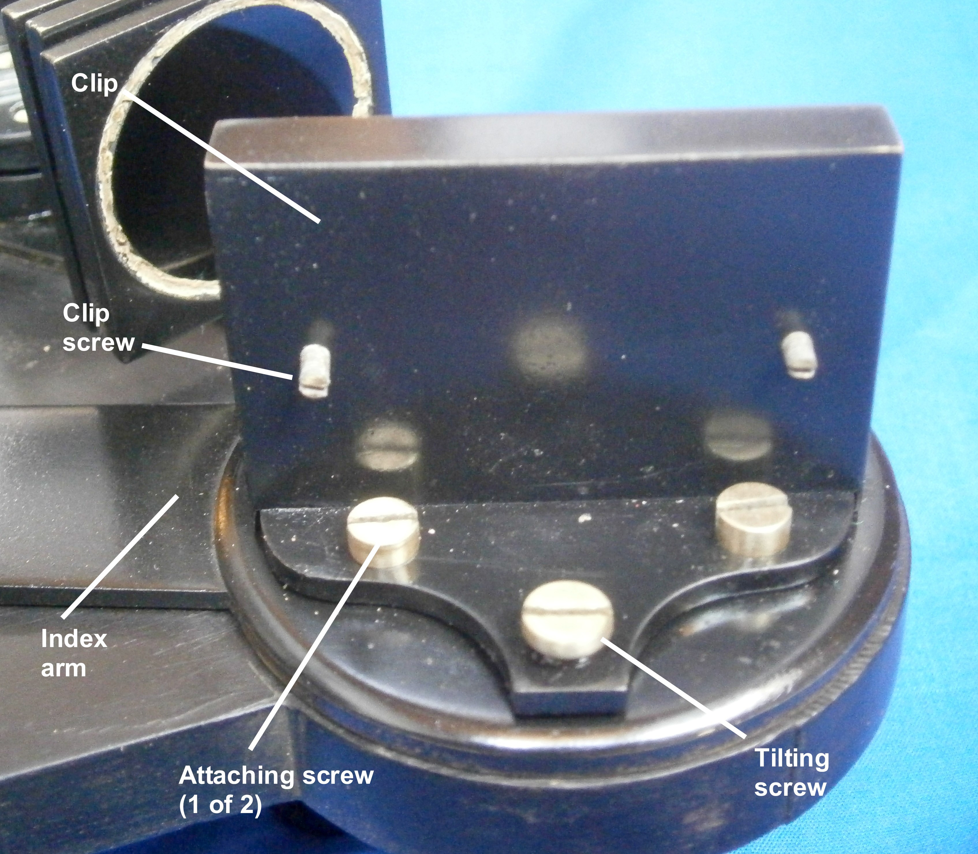
Figure 15: Rear of index mirror bracket.
The base of the index shades can be seen in Figure 3 at the top right. Figure 16 shows the shades and the base in detail.
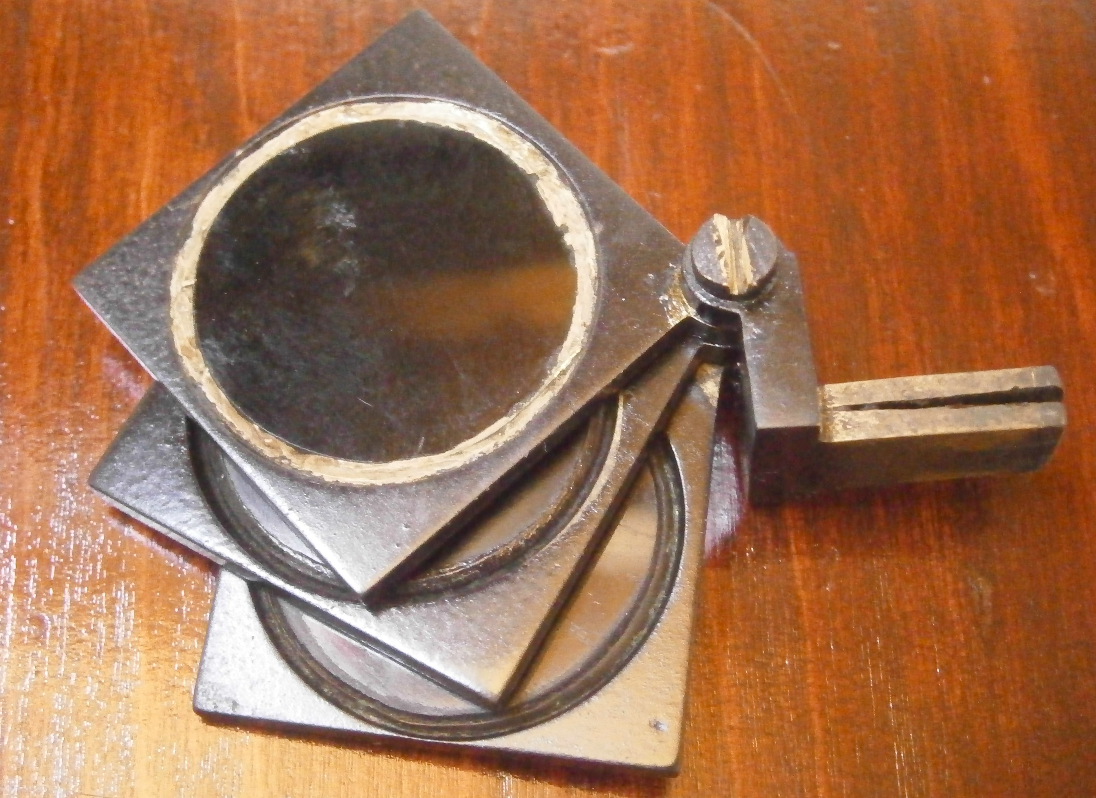
Figure 16: Index shades.
The glass of a shads was usually held in its frame by swaging or deforming the metal over the bevelled edge of the glass, and this can be seen in the bottom two shades. In the top one, the glass seems to have worked loose and is held by antique putty which I have left in place. The shades are separated by washers and held together in a fork which can be closed up by the screw so that they do not flop around. Note in passing that the slot in the screw is vee-shaped, having been formed by a file rather than by a saw, a reflection on the expense and difficulty in the era, of working steel to make a hack or rotary saw.
The split in the base to make a spring allows the shades to be removed easily, an archaic and unnecessary feature in this instrument and presumably a left-over from the time when octants were sometimes fitted with back sights which needed the shades to be moved in position, as in the one I described in my post of June 13, 2018. A brass facing was attached to the sextant by two screws, with a slot for the shades and holes for the horizon mirror base and its adjustment (Figure 5).
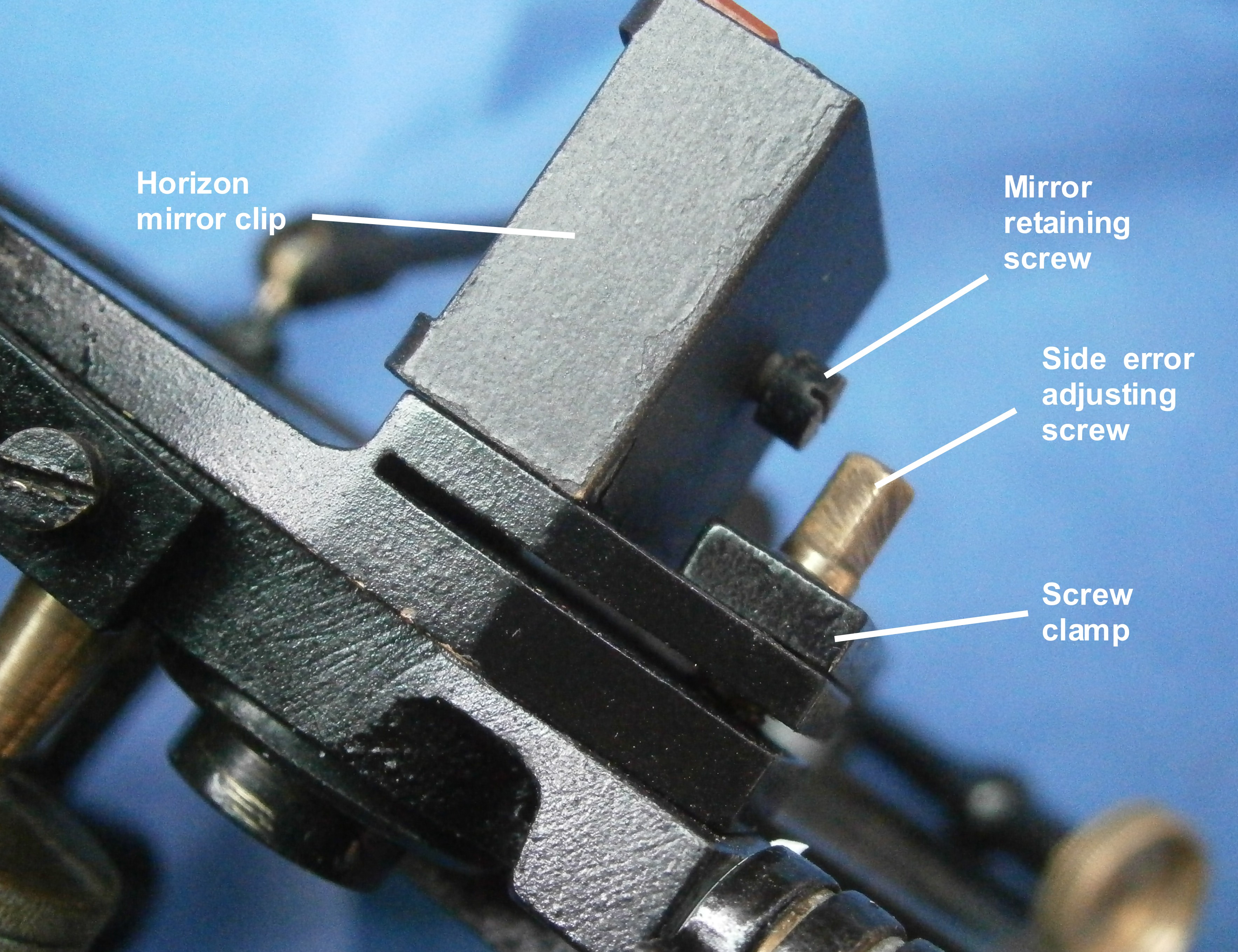
The horizon mirror has a complex arrangement for adjustment. The mirror is held by the clip against a bracket in the same way as for the index mirror. The bracket lies on top of a circular base which can be tilted about an axis of two short pins or nipples by means of two screws to remove side error (see Figure 19 for the details). The base has a short tapered shaft with a square formed on the end which passes through the frame and a straight crank, to be secured by a washer on the other side.
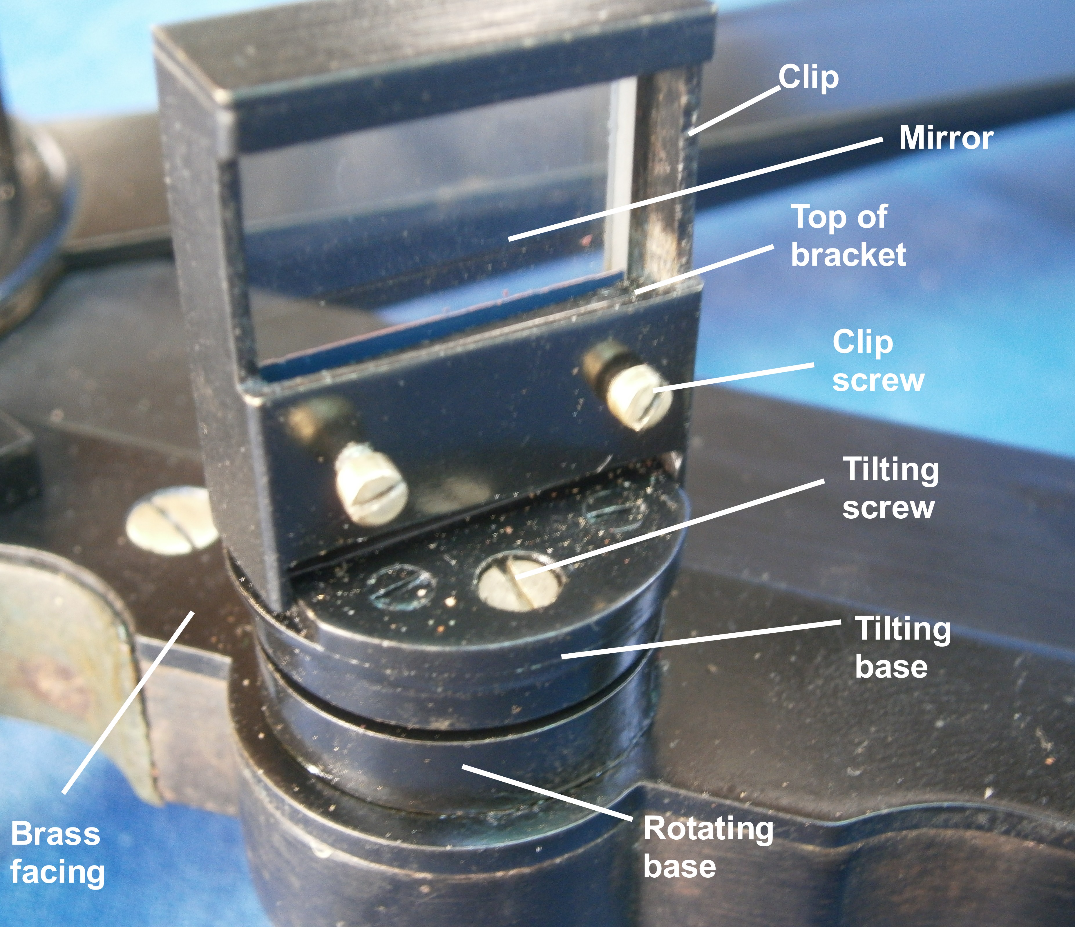
Figure 17: Horizon mirror and bracket.
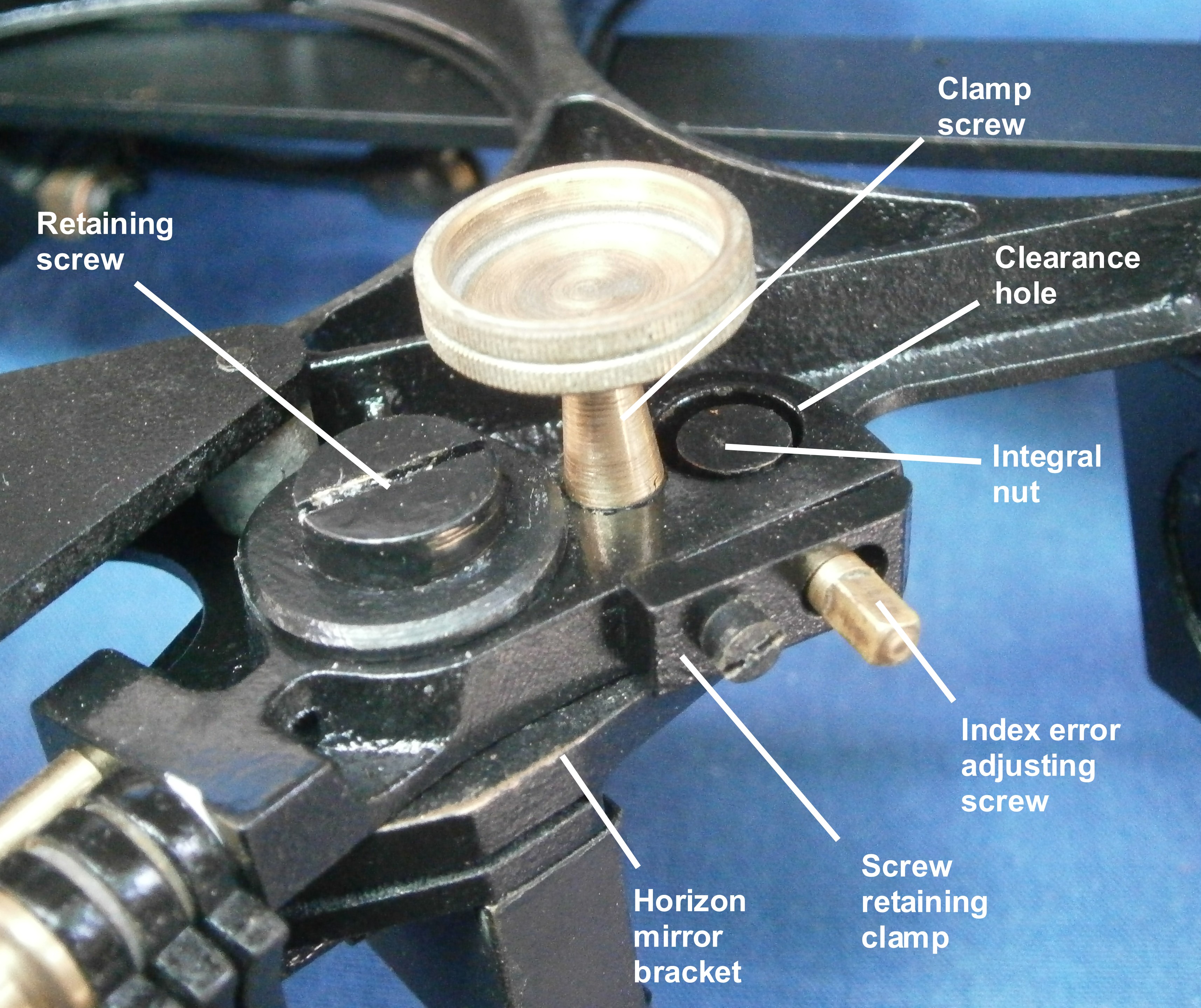
The base can be rotated through a small angle to remove index error by means of a half-nut formed on the end of the crank and a worm screw, and locked in place by a locking screw (Figure 18). The exploded view in Figure 19 perhaps makes the arrangement clearer.
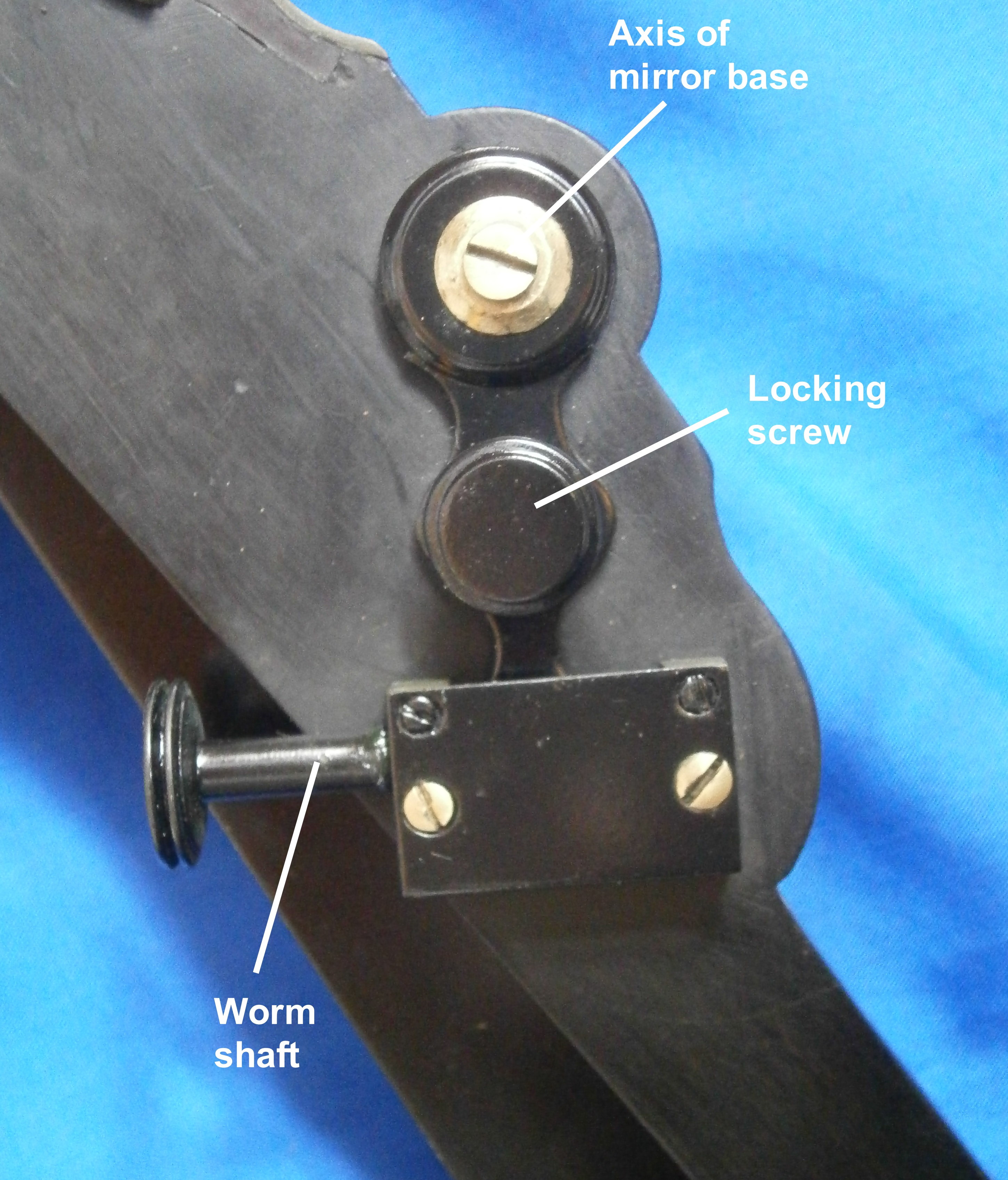
Figure 18: Horizon mirror index adjustment.
When I removed one of the tilting screws it lost its head and I was obliged to make a new one. The old and the new can be seen in Figure 19, lying above the rotating base.
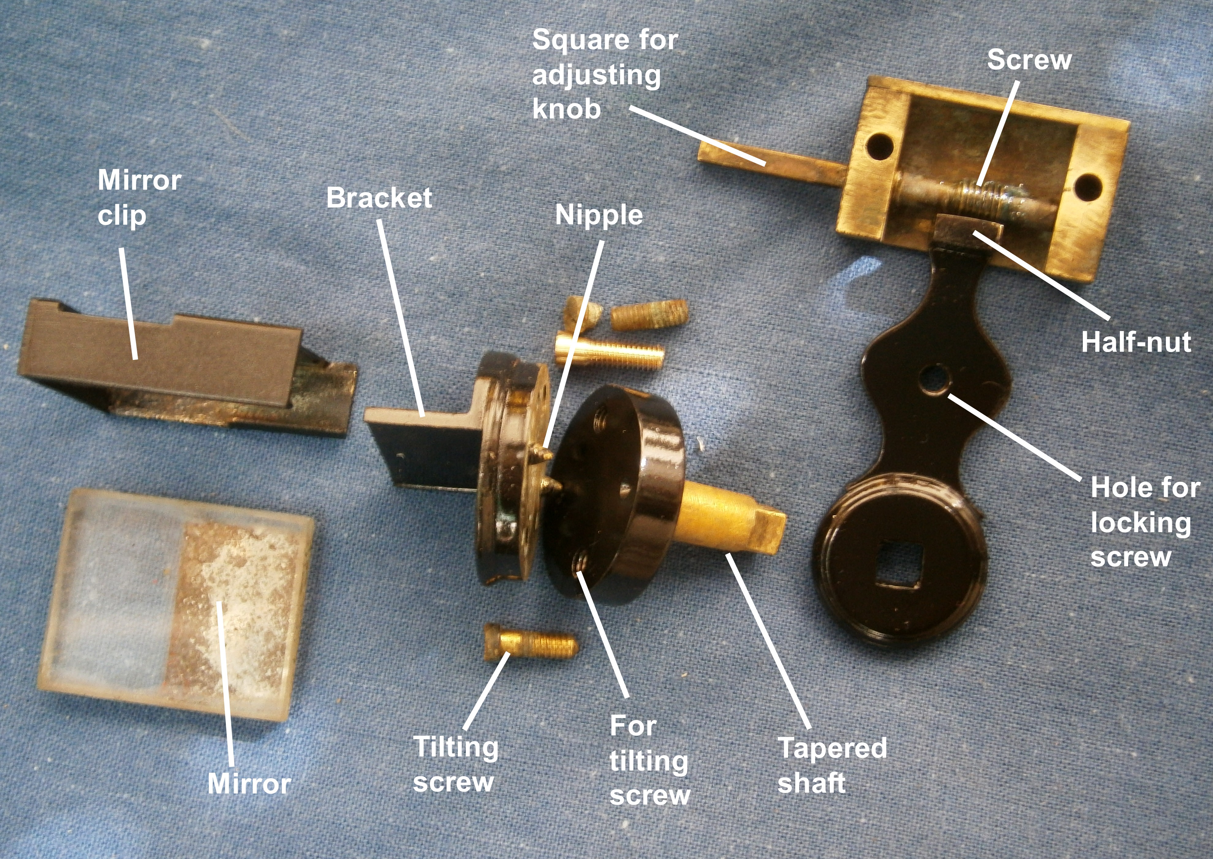
Figure 19: Horizon mirror adjustments exploded.
I have not illustrated an important addition to the octant, the handle, because none was provided. It is likely that this was a basic octant without frills.
You can find many details about the structure of sextants up to modern times in my book “The Nautical Sextant.” available through Amazon and good nautical booksellers like Paradise Cay and Celestaire.
End Note: Murray Peake has been much more patient than I have in tracking down some details of Robert King:
A Thaxter compass in the National Museum of American History has a seller’s card by Robert King whose dates are given as ca. 1769 to 1868, “…an instrument maker from England who spent most of his career in New York City.”
An auction site also lists an octant with King’s label. This is 17 inches in radius, made of mahogany, except for the lower end of the index arm and is fitted with a back sight. It is a very early octant and was probably divided by hand by a specialist in the art.
Robert King appears in Longworth’s New York Register and City Directory for 1812 and 1817, living in Elm Street. By 1827 he is in Lombard Street and left there in about 1833 for 18 Monroe Street. He appears for the first time in Front Street in 1837/38, but at 212, not 219. By 1845/46 he is accompanied by R King Jnr and by 1850 he is no longer listed.
Presumably, King knew his own address. Perhaps 212 was his residence and 219 his workshop or vice-versa?


You must be logged in to post a comment.