On page 64 of Peter Iflands Taking the Stars is a figure showing a small sextant bearing Jesse Ramsden’s name. According to Ifland, this was one of the last sextants made by Ramsden, though by the time of his death he had many workmen and it is unlikely that he made the instrument personally. Part of a batch of instruments sent to me by a friend in Australia for restoration was an identical instrument named W Harris 47 Holborn London. Harris was active from 1816 to 1839, though he almost certainly did not make the sextant bearing his name. It was common practice for retailers to put their own names on sextants, clock, chronometers and the like that had been made by others. Figure 1 shows the sextant in the condition that it reached me and Figure 2 shows the naming.


Apart from the obvious dirt and perished shellac, the scale magnifier, horizon mirror clip and mirror, handle and sundry screws were broken or missing, while the tangent screw adjustment was seized. I followed my usual practice of reducing the instrument to its individual parts for a thorough clean in soapy ammonia solution followed by removal of all the decayed shellac and broken screws.
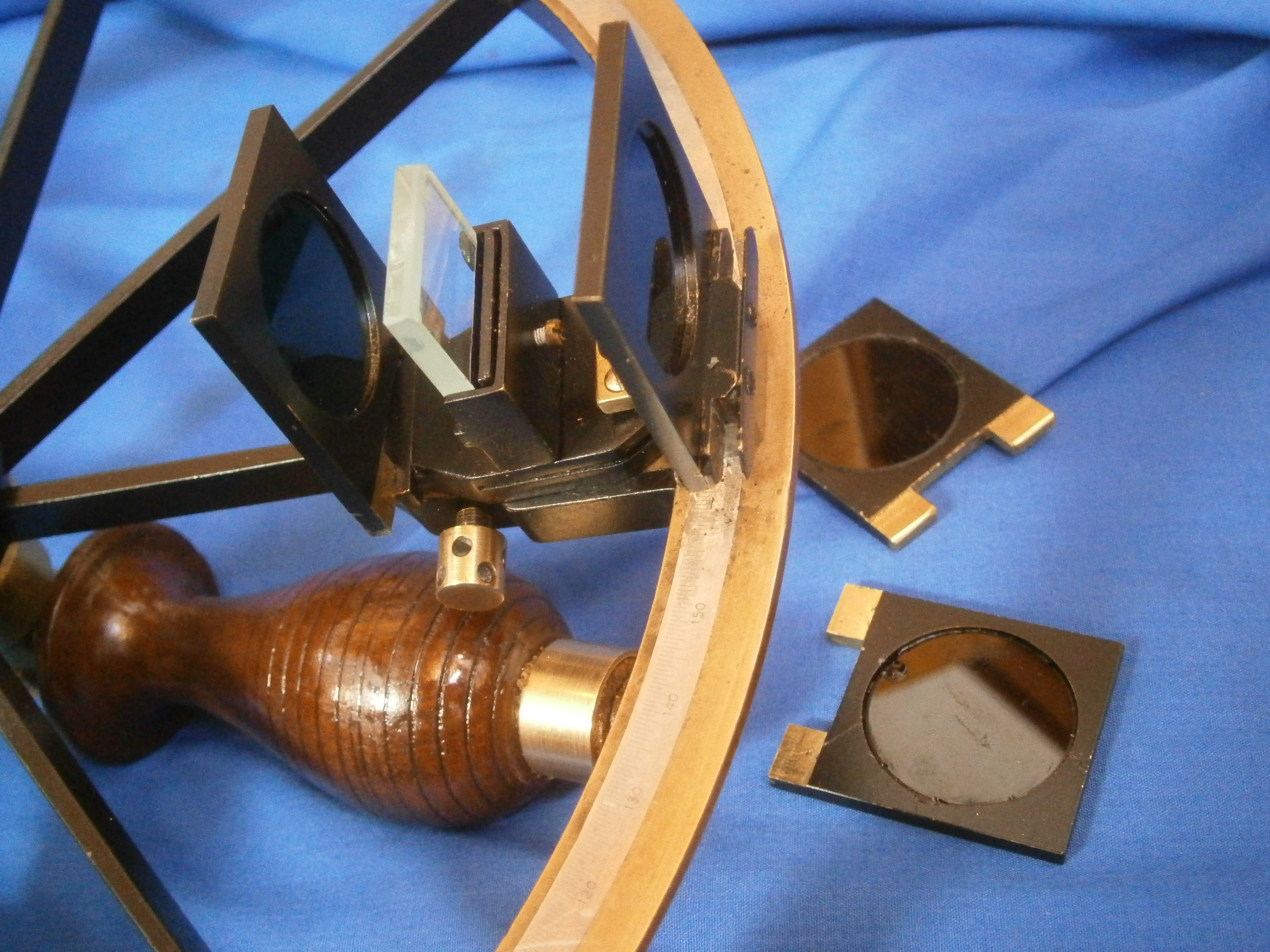
My friend had sent me a box of optical parts which included an Ramsden-type magnifier from a small theodolite complete with threaded barrel, so that my task was to saw out the arm from 3mm brass sheet, file it to final shape and cut an interior thread in the lathe to accept the barrel. Unfortunately, the square on top of the pillar had corroded away, but as the instrument was only to be displayed in future, I simply attached the arm with a screw (Figure 3).

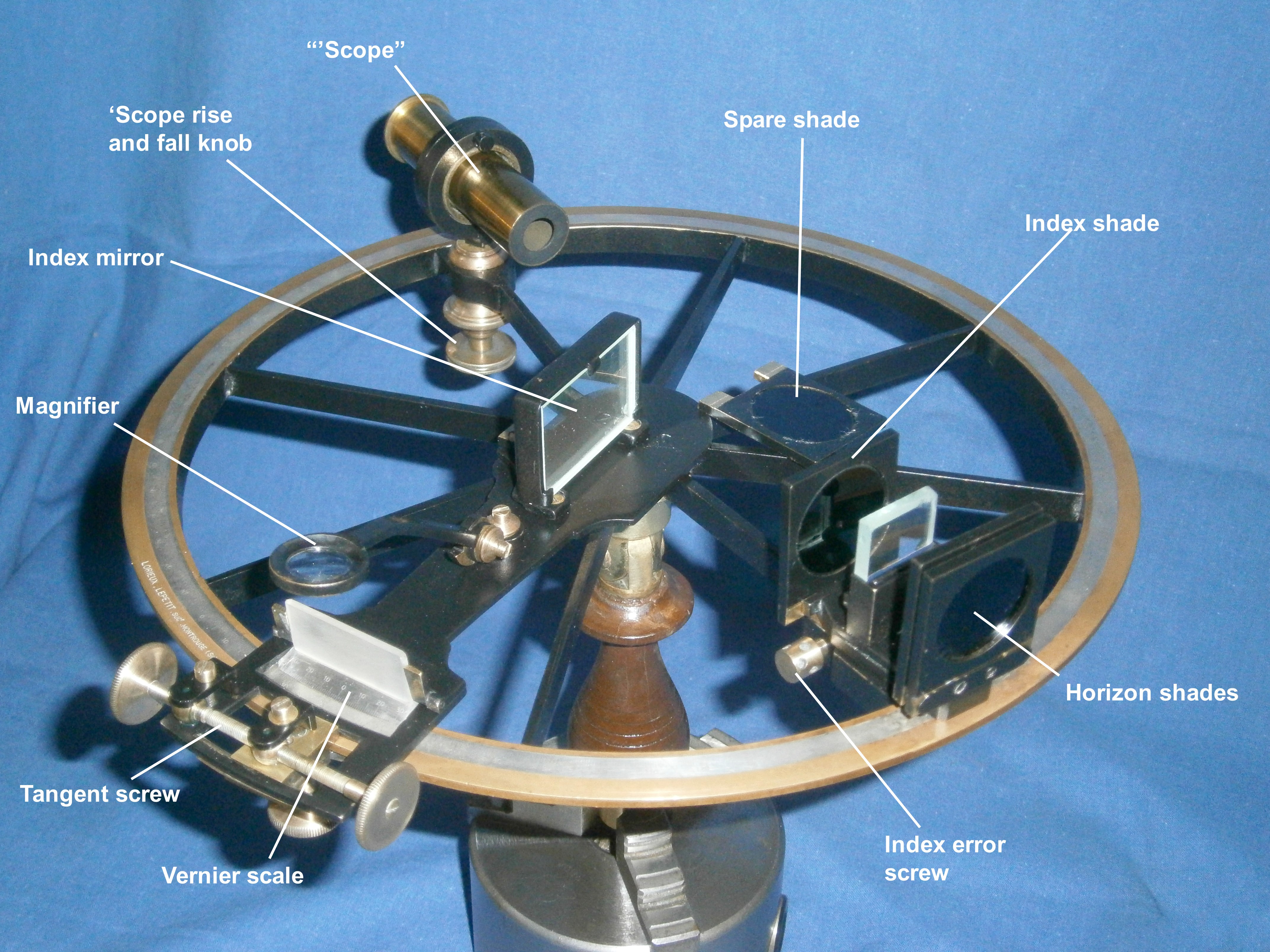
I made the missing horizon mirror clip by folding and soldering thin brass sheet, making and soldering in place a threaded boss for the retaining screw. The clip is visible in several of the figures that follow, including Figure 4 which shows the restoration largely complete.

The index arm bearing is the conventional tapered brass journal in a bronze bearing that Ramsden made much use of in all his instruments and it is possible that he originated the practice. The bearing had become detached from the frame and was much battered, so I had to turn down the outside from its rough cast and bruised state. As there were no screws and it was impossible to determine the pitch of the old ones, as there was no standardisation of screws until the mid-1800s, I had to re-tap the holes to a BA standard and make new screws to fit (Figure 5). A threaded cap covers the end of the bearing and also acts as a leg.

The most striking feature of this little instrument is that the scales are both bevelled so both lie in the same plane, making for easy reading as both have the same contrast. Less obvious is that the scales are read from the centre of the instrument, rather than from the edge of the limb (Figure 6).

The arrangement for the tangent screw is rather unusual The screw is held captive in a bearing which is attached to the clamp, the underside of which may be seen in Figure 5 above. A curved tongue extends from the clamp and fits closely in a groove machined in the lower end of the index arm. The base of the nut retains it in place. The nut is attached to the index arm so that when the clamp is operated and the screw turns, the index arm is rotated and slides smoothly along the stationary tongue.
No provision is made to adjust perpendicularity of the index mirror, rather, it was made correct in the first place, a practice followed by only a minority of late nineteenth and twentieth century sextants. However, there is provision to make the horizon mirror parallel to the index mirror to adjust out side error, and to rotate the horizon mirror to adjust out index error (Figure 7).
There was a wide variety of methods to adjust the horizon mirror, lasting even into the 1940’s with the perverse methods used in the US Navy’s Mark II sextant (described in my post of 30 November 2010). However, Peter Dolland took out a patent number 1017 in May 1772 for “Adjusting and improving the glasses of Hadley’s quadrants and sextant…”. In a letter to Neville Maskelyne (Phil.Trans. 1772 62, 95-98) he described the method which has been used for the large majority of sextants for most of the last century and a half, that of three screws bearing on the back of the mirror and opposed by three springs at the front.
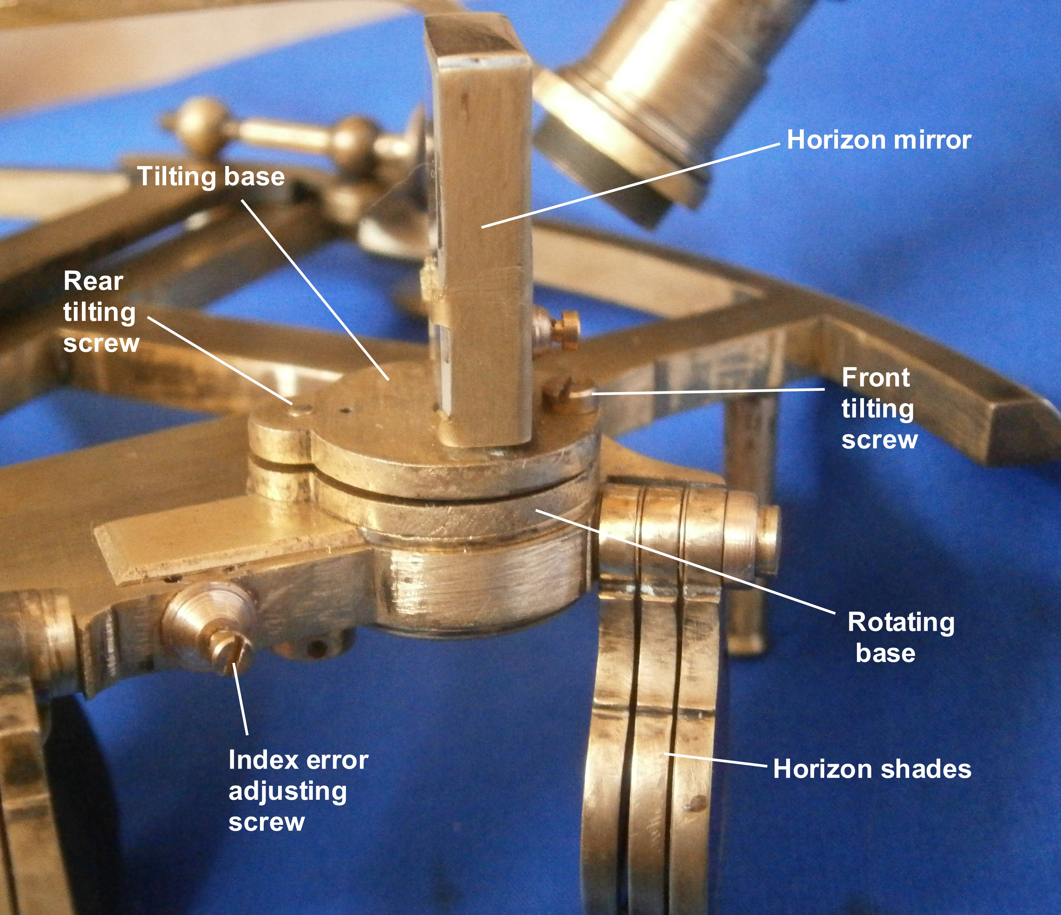
Nevertheless in the late eighteenth and most of the nineteenth century, sextants used a variety of complex and ingenious ways to accomplish the same thing. Figure 7 above shows the approach taken with this little sextant. The horizon mirror is held against three pips on a bracket by a clip and a screw bearing on the back of the bracket. The bracket is mounted on a base which has two pips on its underside more or less at right angles to the telescope axis and the base is rocked with these pips as an axis by means of two screws, the rear one of which pulls from below by means of a knurled screw while the other one pulls from above by means of a slotted cheese head screw. It seems that there may have at one stage been a spring involved that allowed just the use of the front screw, but I was unable from the remains to work out how this was arranged.
This tilting base is attached by the screws to a rotating base and a slot is machined in the face of the frame to accommodate a tongue that ends beneath a rectangular hole in the rear of the frame. A cover extends from the rotating base to cover the roof of the slot (Figure 7) while another cover is provided to cover the hole in the rear (Figure 8). The tongue can be moved back and forth against a stout helical spring by means of a screw that passes through a threaded boss, thus rotating the mirror to adjust out index error. The foot of the boss is retained in the frame by two retaining pins.

All that remains is to note that the arrangement of the four index shades is conventional, while the three horizon shades are neatly fitted in as shown in Figure 7 above. The shades fit over a pillar and are held in place by a squared washer and a cheese-headed screw. The squared washer prevent rotation forces from being transmitted from the shades to the screw, so that latter can be used to adjust the friction without risk of it undoing.
I have two more sextants to describe from the current batch of restorations as family and other commitments decide and hope that you have enjoyed your reading so far. If there is any specific topic you would like me to cover, please let me know at nzengineernz@gmail.com (I have no formal engineering qualifications, but during my clock-building years, someone called me a time engineer…).


You must be logged in to post a comment.