This post was preceded by “An improvised sun compass”, ” C Plath Sun Compass”; “A Fleuriais’ Marine Distance Meter” A Stuart Distance Meter”;“A Russian Naval Dip Meter”; and “An Improvised Dip Meter”
Jaap Brinkert has kindly provided the following post . With his agreement, I have added an occasional comment in blue.
Recently, I won the bidding on a ‘Vintage Marine Sextant’ which I soon discovered to be rather unusual. At first sight, it resembles the Hughes Mk IX bubble sextant as used by the RAF (and others) during WWII (Figure 1 and 2). However, this sextant is intended for marine use. It appears that the German navy started using bubble sextants on board submarines, so that they could take sights when surfaced at night The Hughes Marine Bubble Sextant (HMBS) was the English answer, developed after tests using the Mk IX on board a submarine. {1} “Highly accurate results” seem to me to have been unlikely. One to three nautical miles would be counted good using a normal nautical sextant and the natural horizon.
-

Figure 1: Rear view of Mk IX A and HMBS sextants
A good general description of the device is given in “Specification of instruments exhibited at the seat of the international hydrographic bureau during the Vth international hydrographic Conference, Monaco, April 1947,” in which exhibit number. 8 of Marine Instruments Ltd, entitled “Marine Super Integrating Sextant” is described as follows. “The instrument consists of a sextant, the mechanism of which is totally enclosed with the usual fixed horizon mirror and adjustable index mirror. The mechanism is arranged to give arbitrary increments of altitude of 10 degrees, -10 to 90. Attached to the main body of the sextant by two screws is the bubble complete with eyepiece through which the observer sees the bubble and the object observed. A single instantaneous observation is made by setting the next lowest whole tens of degrees and then using the slow motion to obtain coincidence between the centre of the bubble and the object, reading the altitudes on the tens of degrees scale and the degrees and minutes scale (instantaneous reading.
An averaging observation is made by maintaining the coincidence as nearly as possible during the one-minute period of observation between starting the clock drive and the automatic raising of the cut-off shutter, the altitude being read on the tens of degrees scale and the degrees and minutes scales (averaging).
A second bubble unit is provided, interchangeable with that on the instrument. This unit is exactly the same as the first, except that it carries a 2X Galilean telescopes mounted in the unit itself, which, when sea conditions permit, gives brighter star images than would otherwise be obtained.
Two dry batteries and two spare lamps are supplied.”

Figure 2: LHS of Mk IX A and HMBS sextants.
The Marine Bubble sextant has an entirely different mechanism for averaging, which is contained within the main body, where it is protected from salt spray. It is a continuous integrating mechanism, which runs for one minute. The adjustment of the index mirror also sets the transmission ratio between a slender cone, driven at constant speed by a spring mechanism, and a cylinder connected to the totaliser (Figure 3).

Figure 3: Integrator mechanism.
This is in effect the reverse of the mechanism used in the German SOLD and Kreisel (gyro) sextants, where the inclination of a roller that bears on a shaft moving longitudinally, variably rotates the shaft, on the end of which is attached the read-out. Full details may be found in the post for 4 November 2013 . After the one minute run, the average position of the index mirror is read from a dedicated dial, and added to the setting of the index mirror, for instance 70 +4 35′.
The averaging device for the Mark IX A aeronautical sextant sampled one sixtieth of the reading every two seconds for two minutes, in effect integrating the reading over sixty intervals. The potential disadvantage of this is that if the sampling interval happens to coincide with the approximate frequency of rolling of the vessel, large errors may be introduced. The HMBS, like the SOLD and Kreiselsextant, continuously integrates the reading.
https://www.thejot.net/article-preview/?show_article_preview=85&jot_download_article=85 has a submarine rolling at 2.4 to 3.9 seconds for a closed casing submarine. The implication of this is that it might be best to avoid sampling periods in this range. (Thanks to Murray Peake for this information)

Figure 4: Calibration record.
The calibration record (Figure 4) is interesting as it illustrates the consequence of a difference in timing mechanism between the SOLD and the HMBS. The former contains a “proper” clockwork with balance wheel and escapement. The latter, on the other hand, contains a regulator mechanism which uses centrifugal force and friction (if the regulator turns too fast, it ‘expands’ against a stationary drum, resulting in deceleration). This mechanism needs to be calibrated. The certificate shows a deviation of up to 1%, depending on the set angle). A small error in counter reading follows automatically. The calibration also shows the separate extra corrections for the two bubble units. Using this sextant requires quite a bit of bookkeeping!
As for a normal sextant, the HMBS has a conventional set up, except for the placing of the shades (Figure 5).
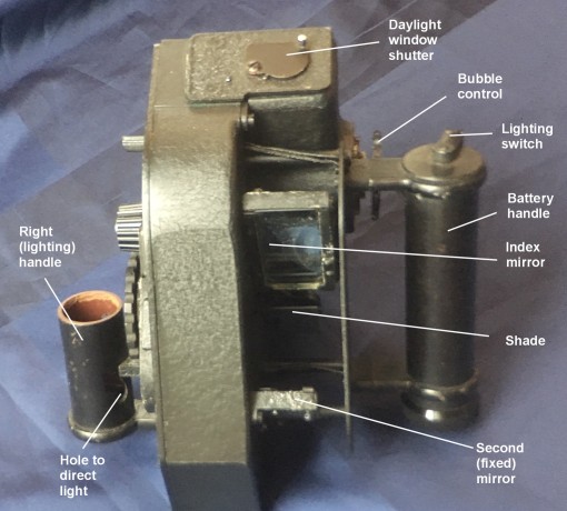
Figure 5: Front view, showing mirrors
The index mirror is rotated on a shaft which emerges from the main housing, and is operated by a mechanism described below. In operation, this mechanism is similar to that of the Mk IX series. There is a large step setting in tens of degrees (-10 (“D”) to +80 ) and a fine setting ( 0 0′ to 14 50′ in 1.5 turns of the adjusting wheel). The index mirror is quite large: 70 mm by 27 mm. Another difference between the Mk IX and the HMBS is the horizon mirror: it has no ‘5 degree increase’ facility, which also simplifies the read out mechanism for the averager. The horizon mirror of the HMBS is fixed; the whole nearly 15 degree range is set by the mirror fine-setting control. The Mk IX index mirror is the same length but only 24 mm wide. In both sextants, the length of the mirror is required because the axis of rotation of the mirror is quite far behind the mirror in order to accommodate a central helical spring and concentric shaft mounting (Figure 6).

Figure 6: Index mirror mounting.
The fixed mirror, on the other hand, is small, only 28 by 20 mm. It is fully silvered, so if the natural horizon is used, it must be viewed past the horizon mirror. In my sextant, both mirrors have deteriorated over time, so I plan to replace them with the help of the local glazier and optician.
There are three small shades (18 mm diameter transparent area). Both the horizon and the index mirror are equipped with two adjustment screws on opposite corners, in the usual fashion. In order to use the natural horizon, it is necessary either to use no shades, or to remove the bubble unit, because the shades, small as they are, cover the whole view. A sun sight using the horizon is therefore not possible with the bubble unit in place, and in any case the instrument would not normally be used in daylight with the natural horizon available..
The aim seems to have been to produce a waterproof device, and this is clear is clear from the fact that to open the main housing, 11 screw must be undone. The separate bubble scope’s lid is fastened by no less than 17 screws. Indeed, the internals looks as if they left the factory yesterday.
Shutter
As in the MkIX series, a shutter cuts out the view unless the integrating mechanism is fully wound or running, to signal to the user that the one minute integrating run is over. The user could then immediately look at his watch on the inside of his left wrist or, more likely on a submarine, call out to an assistant to mark the time. In the Mk IX series, the left wrist was illuminated via a prism in the right hand side handle but this ingenious system which also projects a beam to each of the read-outs using a single bulb, is only partly used in the HMBS. Instead, the handle is attenuated and the prism and some holes omitted. One of the several remaining holes for the lighting of the scales is visible in Figure 5.

Figure 7: Controls and read-outs.
A winding lever primes the integrator by ten strokes of the lever shown in Figure 7 and the integrator is started by operating the lever seen below the ten degrees adjustment knob. As in the Mark IX series this latter is pushed in against a spring load to rotate through ten degrees steps, governed by the three groups of holes seen in Figure 6. Further adjustment is by rotating the fine adjustment knob. Two windows give the instantaneous readings of the altitudes in tens and one degrees, and minutes are read from a further window. A fourth window behind the handle gives the integrator readout, which must be added to the tens of degrees shown in the top window.
The bubble unit
The unit, which is apparently taken directly from the Mk IX series, is attached to the main body by two screws. It contains the bubble mechanism, a partially-reflecting mirror and a mirror/lens assembly (Figure 8). There is a slanted clear glass window on the front and a clear glass window at the rear for the eye.

Figure 8: Interior of bubble unit.
The principle of the bubble unit is shown in Figure 9. The bubble is lit by daylight or a bulb via a Perspex do-nut directly below the bubble chamber. Light rays, shown in yellow, then pass through a partially reflecting glass (shown in white) and are reflected by a mirror-lens combination whose focal length is the same as the radius of curvature of the top of the bubble unit. The bubble is in the focal plane of the mirror-lens, so the reflected rays emerge as parallel rays and are reflected into the eye via the partially reflecting glass. Rays, shown in red, from the observed body via the fixed “horizon” mirror pass straight through the partial reflector. Effectively, the body and the bubble then both appear together at infinity at the eye.

Figure 9: Light paths in bubble unit
Despite the complexity of the sextant, and thanks to the use of a light alloy for all housing parts, the weight is just over 2 kg (2045 g) (including batteries). The German WWII Kreiselsextant (Gyro sextant) weighs by contrast 3 kg.
Lighting.
The bubble unit contains a light bulb and a simple intensity regulating mechanism. A strip with a vee-shaped slit, which is placed between the light bulb and the bubble unit, is moved up or down using a knurled wheel, seen labelled in Figure 8.
The left handle of the sextant is a battery holder for two C size cells. The rotary switch is operated by the left thumb. Turned clockwise it activates the bubble lighting and turned the other way lights the readouts as noted above. The bulb socket for the latter ought to be in the right hand side handle, but it is missing on my sextant.
Box (Figure 10)
The box is made of solid mahogany, and has a stout leather strap over the lid, which can be used to carry it. There are green felt covered blocks to immobilise the sextant. There is a similar arrangement for the spare bubble/scope, which is secured by two keepers (one of which was missing). There are two battery holders, which are obviously intended for the now obsolete Eveready No 8 (3 V). When two batteries of size C are stored in each holder, the lower ones can only be removed by holding the box upside down.
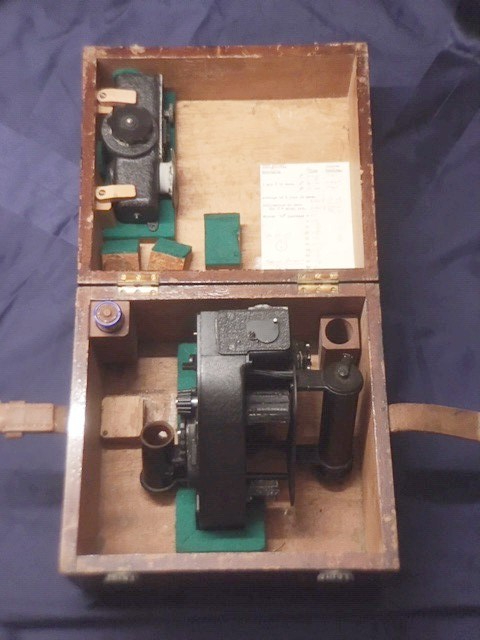
Figure 10: HMBS in its case.
History
I do not know the recent history of this sextant. It was donated to a Sea Scout group and sold on eBay to raise money. Its production date could be close to 1949, judging from the serial number (123).The National Maritime Museum at Greenwich has a Marine Bubble Sextant with serial number 114 with a certificate by Henry Hughes & Son dated 3 March 1949.
The certificate of my sextant is dated 18 July 1978, issued by Fenns, Farnborough Ltd. The sextant is also marked FEN/R/7/75. Fenns did the calibration of the instrument for the Air Ministry, so it appears the sextant was still in the care of the Air Ministry in 1975. Whether it was also in use is impossible to say. It seems likely that the sextant was sold sometime after 1978 and perhaps used at sea, as some external parts have corroded. However, this could also have occurred in humid storage conditions.
Concluding remarks
My impression is that the Hughes Marine Bubble Sextant was a product that was developed just too late to play a role in WWII, and which was unsuccessfully marketed after the war. Online, there is evidence of fewer than ten individual examples, two of which are in museums, three in past auctions and two in unrelated accounts. Some of these could even be the same. The two serial numbers I know are 114 and 123, which doesn’t tell much. This sextant used parts from the Mk IX (bubble unit, handle, general lay-out), but contains a completely new integrating mechanism. This mechanism may have found use in later aircraft or submarines sextants of the periscope type. It is clear that a lot of effort was put into designing and producing this sextant, so it must have been a disappointment for the manufacturer. Nevertheless, as a nautical sextant, it deserves a place on this blog. I have found a number of reports and articles on the internet which mention this sextant, but I’d like to hear from anyone who has more information.
If you enter this in the “Comments” section (below), I will forward your information to Jaap.
End note: [1] “Another enterprise of Plaskett and Jenkins was entirely successful in itself- the demonstration that the bubble sextant could be employed to aid the fixing of position of a submarine surfacing only at night when the sea horizon is invisible. Pleskett obtained highly accurate results from observations made on board a submarine off Start Point. As a result the ‘Hughes Marine Bubble Sextant’ made its appearance in 1944 and underwent trials, but apparently it never actually went into service.” (Biographical Memoirs: Harry Hemley Plaskett (5 July 1893 – 26 January 1980), Biogr. Mems Fell. R. Soc. 1981 27, 444-478, published 1 November 1981)
Readers who own a Mark IX series sextant who would like to know more about its construction, operation and restoration could do worse than buying a copy of my restoration manual. . See “My Bubble Sextant Restoration Manuals” for details.




You must be logged in to post a comment.