In a recent exchange of e-mails with David Monton Farrioli of Breda in north-eastern Spain he drew my attention to an illustration in a book on navigation written in Spanish (Astronomia Nautica y Navegacion, by Curbera, M. and Jimenez, M.). At Figure 2301 of the book is shown a vernier sextant which the text says is of the type “Guardiamarina” and constructed in Spain. One might be excused for thinking that “guardiamarina” means some form of marine force, but in fact the word correspnds to the English “midshipman” or “naval cadet” and we may conclude that it was intended as a low cost option for naval cadets. It was probably made by Empresa Nacional de Optica (National Optical Enterprise) or ENOSA, an enterprise dating from the period following the Spanish Civil War and the Second World War. Spain’s support for the wrong side in this latter conflict led her to be shunned by most European nations and the enterprise was apparently set up to manufacture optical goods of all types within Spain. A micrometer sextant, the Fregata, was also made but I have yet to see an example.
I was not previously aware that there were any Spanish sextant makers, at any rate in the twentieth century and feel that it deserves at least a footnote. Normally, I describe sextants in my collection or that pass through my hands as I restore or repair them for friends, but on this occasion I will describe one or two points of interest of the sextant based on viewing only an illustration. Not the least point of interest is that it was made in the second half of the twentieth century when manufacture of vernier sextants elsewhere had for all practical purposes ceased in favour of micrometer (or “drum”) sextants.
The illustration in Figure 1 is by courtesy of E.T.S. de Nautica y Maquinas de A Coruna, photo by Pablo Lopez Varela, and the original may be viewed at http://www.caosyciencia.com/visual/imagen.php?id_img=464 . According to caosyciencia it dates from the 1960s.

Figure 1: Guardiamarina Vernier Sextant
To help readers whose first language may be Spanish and who wish to know the English equivalents, Figure 2 shows the same picture with labels giving the name of the parts in English.
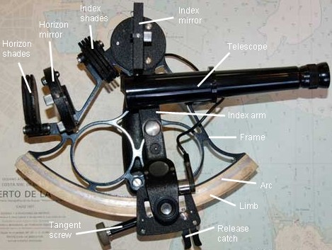
Figure 2: English captions.
The frame is I assume made of bronze and its pattern would not have been out of place in a late nineteenth century instrument. However, the size of the mirrors and shades, and the round horizon mirror would not have been out of place in the second half of the twentieth. Very unusual for a vernier sextant is the scale lighting system, while the unusual arm that carries the magnifier is provided with a diffuser screen for viewing the scales in daylight. Chapter XXIII gives a careful explanation on page 182 of a vernier reading to 20 seconds which the authors say explicitly is of the same type as the Guardiamarina. Figure 3 gives a close-up view of the lower end of the index arm.
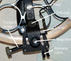
Figure 3: Close up view of lower end of index arm.
It is not possible to see how the release catch operates. On the face of it, the worm must be released from the rack in the plane of the frame, but it is not clear whether the teeth of the rack are on the edge or the back of the limb. The angle of the tangent screw to the index arm seems to be against the worm bearing on the edge of the rack, while the arrangement of the release catch seems to suggest that it may do so. Perhaps the release catch operates a roller against an inclined plane, in so doing swinging the worm away from a rack machined on the back of the limb. Kelvin and Hughes used a similar arrangement in their Mark III Survey sextant, though to release the worm of a micrometer sextant (See “Sounding Sextants” on this site).
The telescope is of quite remarkable length. It is not possible to deduce its type. It may be a terrestrial telescope adapted to the sextant. At any rate, one can observe that the mounting bracket seems to be rather insubstantial. In a sextant reading to 20 seconds, there would be little point in a telescope exceeding a magnification of x3 or x4.
If any reader owns one of these sextants or has additional information, please do contact me with details and, if possible, photographs of the release catch mechanism.


You must be logged in to post a comment.