Another Sounding Sextant

17 11 2018

A little while ago I acquired yet another sounding or survey sextant for a relatively small sum. It is based on a Cassens and Plath nautical sextant. As with most sounding sextants, it has no shades, but where the index shades would normally be mounted is a leg and where the horizon shades would be mounted is a bracket for a pentagonal prism or “penta prism”.

Over two hundred C&P surveying sextants were obtained by the US Coast Guard Service from Weems and Plath around 1978, provided with a handle that would make holding the instrument horizontally easier and stripped of the lighting system, to save unnecessary weight. In my instrument, which bore a USGCS label, the lighting system is intact and there is no provision for a modified handle.

Figure 1 shows the state of the instrument as received and it had plainly not been well loved in the autumn of its life (by the way, the hand holding it is not mine).

As found labelled

Figure 1: C & P Sounding sextant as found.

My usual method is to strip the sextant down to the last screw and washer and then to clean and repaint everything, stripping all the old paint off if necessary. As I go, I fix electrical faults, renew wiring, replace mirrors , clean optics, and re-grease moving parts. As I have elsewhere in the blog described these activities, I will not go into them here, but instead focus on the main point of difference from other sounding sextants: the pentaprism. I have given a very brief account of the use of sounding sextants in the post for 26 April, 2009, and this should be read in conjunction with the comment kindly sent by Peter Catterall.

In a pentaprism, the emerging ray is at right angles to the incident ray, and the angle between the two rays (really two parts of one ray) is independent of any rotation of the prism about an axis parallel to any of its faces.  The image is not inverted or reverted. However, if the prism is rotated about another axis, the incident and emergent rays will not be at a right angle. Although there are two internal reflections in a pentaprism, they are not total internal reflections as, say, in a 90 degree Porro prism, and so the reflecting surfaces have to be silvered. If the paint film and underlying silvering gets damaged, the damage will be apparent in the view through the prism.

OLYMPUS DIGITAL CAMERA

Figure 2: Position of the pentaprism.

Figure 2 shows the location of the pentaprism behind the clear glass of the horizon mirror. It is located in a spring-loaded bayonet socket by means of a peg, which allows it to be placed in two positions (Figure 3). Rotating it anticlockwise locates it in the position shown in Figure 4.

Pentaprism base

Figure 3: Pentaprism base

When located in this position, if the index arm is set at 90 degrees, the two light paths should be parallel, so that a distant vertical object should form a continuous vertical, straight line when the instrument is held with the frame horizontal. For this to happen the faces of the prism must be at a right angle to the frame of the instrument, so three adjustment screws are provided to bring this about. It is a great deal easier to do this if a 2 mm diameter torus of thin, soft copper wire is placed centrally under the face opposite the adjusting screws, so as to allow a little rocking  to take place. This is a little simpler than following the official advice promulgated in the US Coast Guard Service manual, available on line here: http://www.dtic.mil/dtic/tr/fulltext/u2/a059986.pdf  The prism is held in place by two rectangular “springs” which offer quite a lot of resistance to the movement of the prism when adjusting it, so it is easier simply to leave them a little proud of the prism faces and rock the prism as I have suggested. The adjusting screws then do double duty of adjusting and retaining with the springs as back-up retainers.

Any index error of the sextant must of course be allowed for, in addition to any error found with the prism in place, and normal checks for perpendicularity of the index mirror and side error made and corrected.

Calibration

Figure 4: Position of prism to check index error.

Figure 5 shows the prism in its orientation in normal use and you can see that with the index arm set at 30 degrees, the rays diverge by 90 + 30 = 120 degrees, the practical limit for a normal sextant, where the reflected image is reduced to a narrow slot.

30 degrees

Figure 5: 90 + 30 degrees = 120 degrees.

Figure 6 shows how 180 degrees can be measured by setting the index arm to 90 degrees. The ability to measure large obtuse angles improves the strength of position lines when fixing the position of aids to navigation.

90 degrees

Figure 6: 90 + 90 degrees = 180 degrees.

Although the stout case could be mistaken for solid wood, it is in fact some sort of laminated wood, as witnessed by the delamination of the outer layers of the top and bottom. It seems strange that an instrument destined for use in a damp and sometimes wet atmosphere should not at least use marine grade laminates for its case. The corners are keyed mitre joints which give both a very neat appearance and very adequate strength. Note that the key should be sited as close to the inside angle as feasible, as shown in Figure 7.

Case corner

Figure 7: Keyed mitre joint in case.

Figure 8 shows the instrument less its telescope in its case. It cannot be stowed with the pentaprism in place, though with a little more thought, the pocket for the sextant handle could have been rotated anti-clockwise and moved to the left a little to give room for both the prism and the originally supplied prismatic monocular.

In case

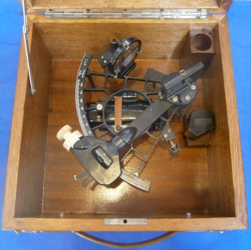
Figure 8: Instrument in its case

The telescope with my sextant is a standard 4 x 40 C and P offering except that there is a glass in front of the objective lens that acts as an astigmatiser with stars, drawing out the point sources into lines (Figure 9). It has no effect on extended images. I cannot imagine how this works, so if any reader knows, I should be glad if they would share their knowledge with me.

I hope to be able to add two or three more posts to this blog before the end of the year, after which it will the turn of a marine chronometer to be described on my other web site, http://www.chronometerbook.com .


Sounding sextants 3

16 07 2009

Hughes and Son Double Sounding Sextant

A post on another  obsolescent navigation instrument seems to be apt, against a background of a newspaper report from Honolulu: http://tinyurl.com/m8nvxd  According to the report, in February this year a 9,600 guided missile cruiser, the Port Royal, ran aground at night near the entrance to Pearl Harbour. The causes were complex, but could perhaps be summarised as “When the modern navigational systems broke down or gave conflicting results, noone looked outside the ship in an attempt to fix its position.”

A double sextant, not to be confused with the reflecting circle, allows almost simultaneous horizontal angles to be measured between three objects. By applying the results to a station pointer (sometimes called a three-arm protractor), a fix can very rapidly be plotted on a chart. The speed with which this can be done is particularly useful when the vessel is travelling at speed. I have updated the account of fixing by simultaneous horizontal angles in the first post of this series, Sounding sextants 1.

Early double sextants from the first half of the nineteenth century had two index arms rotating about the same axis on a quintant, with one vernier reading on the inside of the limb and the other reading on the outside of the limb. By the third quarter of that century, Henry Hughes and Son were making double sextants in which the frame was circular. Double sextants from any period rarely come on the market and do not seem to be sought-after. Nevertheless, I was pleased to be almost the only bidder for a Hughes double sextant dating from 1951 or 1952.

The layout has not changed from the C19 version, but the 1950s instrument has an alloy rather than a bronze frame, is provided with micrometers, and has a telescope with an interrupted thread  to allow it to be deployed rapidly. The form of the mirror frames and the handle remain the same. This photograph gives the general arrangement:

GA1

The aluminium alloy frame of about 86 mm radius is in the form of a three spoked annulus with two lengths of rack on the periphery, and is held in the hand by means of an octagonal plastic handle that screws into the hub. The worms of two micrometers at the end of alloy index arms engage with the racks. The zeros of the scales of degrees are set 140 degrees apart. The narrow mirror of each index arm rotates independently about the centre of the instrument and the x2 by 30 mm Galilean telescope looks past their left hand edges at the middle mirror, which is about 35 mm square. This is unsilvered in a middle horizontal strip, so that the user has a direct view of the central object and reflected views of the right and left-hand objects. The mirrors are provided with adjusting screws which have screw-on protective caps.  The next photograph shows the layout, with the index mirrors set at micrometer readings of 60 degrees.

GA2

A feature of the mirrors not apparent from the photographs is that tiny discs of brass have been glued with shellac to the backs of the mirrors where the adjusting screws bear. The whole of the back has then been coated with a thick layer of varnish to seal the silvering. This is an approach that I imitate when restoring sextant mirrors, as the silvering often begins to deteriorate where the protective paint or varnish coating has been damaged by the point of a screw.

The next photograph shows a view of the underside of the instrument. The form of the handle is unchanged from 75 years previously.

Handle

As the sextant has a radius of only 86 mm it is possible to have micrometer drums of a useful size without having to have a conical worm in order to have the thread tangential to the rack while the worm axis is offset. In turn, having a cylindrical worm allowed Hughes to put into practice their 1929 patent (U K Patent number 309,648), in which the worm swings on a swing arm chassis out of the plane of the rack when the release catch is operated. The more usual arrangement in sextants is for the swing arm chassis to pivot in the plane of the rack. The next photograph may help to illustrate the Hughes arrangement:

Swing arm

The micrometer drums are pinned on to the worm shafts and the plastic of which they and the indexes are made is of a dark brown colour rather than a more pleasing black. Possibly they were originally black and have deteriorated over the years. They are divided into minutes and, despite the ample diameters of the drums, the scales seem inexplicably crowded.

The telescope can be very rapidly deployed. It has a relatively coarse interrupted thread. One has only to line up the white dots on the telescope and its mounting and rotate through less than an eighth of a turn to secure it in place. It is focused by sliding the eyepiece draw tube.

Scope thread

 The sextant came to me without a case, so my first step in its restoration was to make a new case for it. I used the tropical hardwood, kwila, for the carcase and sapele, sometimes called African mahogany, for the internal fittings. I followed Hughes’s practice of placing the handle on the side of the box, so that it can be set down without damaging the hinges, and of arranging the latch hooks both to point to the floor when the case is being carried. The joints are box dovetails, not a 1950’s practice, at which time comb joints were the norm.

I plan eventually to strip the paint off the sextant, deal with the small areas of corrosion and repaint it.

100_2891


Sounding sextants 2

6 05 2009

copy-of-100_2522

The Survey Sextant Mark III, by Kelvin and Hughes, was designed specifically as a sounding sextant, rather than being an ordinary sextant without index or horizon shades. It has a cast aluminium alloy frame with a stainless steel worm running in the rack, which is one with the frame. The limb is divided to 140 degrees. The micrometer reads to single minutes. There are no shades nor is there anywhere to put them.

In the preceding post about sounding sextants, I pointed out that most of them were not provided with handles appropriate to their normal use with the frame horizontal, nor with legs placed so the instrument could easily be set down without changing hands. This sextant has a solid mahogany wooden handle attached only at the top by four very substantial screws, but it is still better adapted to vertical rather than horizontal use. The legs, however, can be unscrewed from the back and replaced in tapped holes in the front of the frame, circled in white in the photo above, so the instrument can easily be put down.

100_2736

The Galilean telecope has a large objective lens of 45 mm diameter to give a large field of view, and a magnification of   x3.  It is very solidly attached to the frame via a spigot and three screws, and there is no rising piece nor provision for adjusting collimation. At the level of precision required of this class of sextants, the telescope mounting would have to have been very badly made indeed to have been significantly out of collimation, and Henry Hughes and Sons always produced instruments with fine workmanship.

The large, circular, sealed index mirror, 55 mm in diameter,  has no provision for adjustment either, but machining surfaces that are truly at right angles to each other is one of the more elementary operations in the engineering workshop. The  circular “horizon” mirror, 35 mm in diameter, is also sealed and has provision for adjusting out side and index error, more details of which will be found in my book, The Nautical Sextant.

Hughes and Son were granted a patent in 1928 (UK Patent 309,648) for a method of engaging and disengaging the worm from the rack, by swinging the worm out of the plane of the rack. They do not seem to have used it prior to WW II, but did make use of it in this sextant and in their handy little double sextant.

Its light weight certainly makes it easy to hold, but it has an annoying feature in use when taking angles greater than about 80 degrees: the horizon mirror “sees” past the edge of the circular index mirror over one’s right shoulder, as well as providing the image reflected from the index mirror, so that there are three images to sort out. With practice, though, one soon learns the position and form of the three images and to ignore the over-the-shoulder one.

This instrument’s former home was in the Solomon Islands and may indeed have been used by one of my uncles when he was Marine Superintendent in Honiara in the 1950s. It was not in good condition when it reached me and it had no case. It seemed to me fitting to make the latter out of the tropical hardwood kwila, which is found in the Solomons, and I followed Hughes’s style in putting the handle on the side and having the hook latches (cut by hand from 2.5 mm brass) arranged so that gravity keeps them both in place. The whole instrument has been repainted. The graduations and labellings were then cleaned out and re-filled with white paint.

case1

If you love detail or simply would like to know more about the structure of your sextant, you will find much more along these lines in The Nautical Sextant . Next in this series will be an account of a double sextant by Henry Hughes and son.


Sounding Sextants 1

26 04 2009

Older textbooks on surveying usually illustrated a nautical sextant in the chapter on instruments, but there is another category of sextant used specifically for hydrographical surveying: the survey or sounding sextant. As this was used to measure mainly angles between terrestrial objects in order to fix the position at which a sounding was made, there was no need for shades. The telescope provided was usually a Galilean of two to five power, sometimes provided with two eyepieces and, together with the mirrors, of larger size than usual for the period. Some were also provided with a peep sight.

Surprisingly for an instrument that must have been picked up and set down a large number of times when taking a line of soundings from a small boat, most sounding sextants were held in the right hand and had the legs on the same side as the handle. This meant that the sextant had to be passed to the left hand before it could be set down on its legs. Although they were mostly used with the frame horizontal, few were provided with handles that took this into account.

The following photo shows a sextant named Stanley. Unfortunately, this honorable name in the instrument-making world has been stolen by purveyors of so-called replicas of pocket or box sextants, but the firm of W .F.  Stanley and Co was established in 1853 and were well known manufacturers and sellers of surveying and other scientific equipment into the second half of the twentieth century.

100_25291

In 1926, they merged with Heath and Co, a respected firm of sextant makers. This sextant plainly came from their workshops, as demonstrated by the “‘Hezzanith’ Endless Tangent Screw Automatic Clamp” placard beneath the vernier scale.

The silver arc of 142 mm radius is divided up to 200 degrees though the instrument can usefully take angles only up to 140 degrees, beyond which the view of the reflected image is reduced to a very narrow slot. The vernier reads to 20 seconds.

The lozenge-pattern frame of cast bronze is rather delicate and, except for the arc, was only 8 mm deep. It was the least resistant to deflection of the C20 frames that I tested to include in Table I of my book, TheNautical Sextant .  However, this is unlikely to have had much practical significance, given the class of observations it was used for. The black japanned finish is among the finest I have seen in any sextant.

The telescope is a little unusual in that it screws into its non-adjustable mounting at the objective end. It would otherwise foul the unusually large (for its time) index mirror. It is provided with two eyepieces giving magnifications of x 3 and x 5. The kit also included a peep sight, described as a “sighting head” in Stanley’s catalogue. This screws into the telescope mounting  and is essentially a heavy, knurled brass disc with a central 2 mm diameter hole.

stanley-survey

In taking a line of soundings, the preferred method was to set up two signals at known positions on the land, more or less perpendicular to the shore. These would be kept in line as the boat sailed out and a sextant angle was measured between the line and another shore object each time a sounding was taken. A more complex method is to take simultaneous angles between three shore objects of known postion and plot their intersection. This is the well-known, but perhaps little-used three point fix. W Norman Thomas’s Surveying (London, 1926) gives two mathematical and five geometrical methods of plotting the fix, but the preferred method was a mechanical one that used a station pointer (U.S. three-arm protractor), shown in the next photograph.

station-pointer

The two included angles are set on the instrument and the three arms lined up on the three points observed. The point of intersection is then pricked through on to the chart. Most of the station pointers I have seen have been vernier instruments reading to 20 or 30 seconds, but the one in the photograph, of Russian origin, has a pair of micrometers that allow rapid reading to one minute. The angles could of course less accurately be laid of on a piece of tracing paper and the fix pricked through.

The Admiralty Manual of Navigation Volume I of 1964 gives as the advantages of fixing by horizontal angles: a) it is more accurate than a compass fix; b) it is independent of compass errors; and c) the angles can be taken from any part of the ship. It says the disadvantages are : a) it takes longer than a compass bearing fix;  b) three suitable objects are needed; and c) If the objects are not correctly identified or charted the fix will be false without the error being apparent.

Next in this series will be a Kelvin and Hughes survey sextant Mark III.