You will find an account of the restoration of this sad instrument in the post for 20 October 2016 in the category “Interesting Overhaul Problems.”
A Battered 1940’s Observator Sextant
20 10 2016Comments : Leave a Comment »
Categories : Observator Sextants
A Battered Observator Sextant
20 10 2016By clicking figures with an asterisk * you can enlarge them to see more detail. Return to the text using the back arrow.
This post is preceded by “Restoration of an early C19 ebony quadrant”, “C Plath battery handle structure; “C Plath sextant lives again”; “C Plath Micrometer Sextant”; “A Damaged Rising Piece”, “SNO-T Mirror Bracket Repair”, “A Worm Turns”, “The case of the broken screw”, and “Worm with wrong thread angle?”

Frontispiece*: Before.
Recently I acquired a 1940’s sextant by Observator of Rotterdam which I knew was not perfect, but the extent of the imperfections did not become fully apparent until it arrived about two weeks ago. The seller had very fairly pointed out a broken leg and a broken peg on the device that is supposed to secure the instrument in its case (Figure 1), and the absence of mirrors and their clips was evident from the photographs. Unfortunately, the second peg of the securing device gave way while in transit, so that the sextant rattled around in its case and the horizon mirror bracket got distorted (Figure 4), the telescope rising piece got both twisted and bent and the micrometer worm shaft got seriously bent (Figure 6).
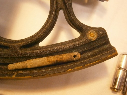
Figure 1: Broken leg and peg as found
I have dealt with how to mend broken legs, using this instrument as an example, in my post of 7 October 2016, Mending Broken Legs, so will not write any more about it here.
The pegs on the securing device were riveted into a plate which was screwed firmly to the base of the case (Figure 2) and all that was needed to re-secure them was to clean up their bases and, using the ball of a ball-pein hammer, to rivet them back in their holes.

Figure 2: Device for holding sextant in its case.
The device is not well suited to its task. The pegs each pass through a hole in the handle of the sextant and, projecting into the upper holes which is lined with a brass bush is a spring-loaded pin (Figure 3). This latter is supposed to engage in a groove in the upper peg, but, while it may locate the sextant, it does not secure it very well. I plan to add a couple of wooden buttresses to the lid of the case, so that when it is closed the sextant will be held securely.

Figure 3: Spring-loaded pin that “secures” sextant.
The distorted horizon mirror bracket (Figure 4) had most of the distortion removed by giving a squeeze in a vice and then a few well-directed blows with a soft-faced punch did the rest

Figure 4: Distorted horizon mirror bracket.
The extent of the damage to the telescope rising piece is not immediately apparent from Figure 5, though with a little imagination, a twist is apparent, and it was certainly obvious that the telescope was not pointing towards the horizon mirror. The objective lens was also canted downwards so that instead of clearing the index arm, it was jammed against it. Straightening the part simply involved removing the telescope and its ring and placing first the square upright in the vice to untwist the soft brass, followed by clamping the ring to straighten the upright in two dimensions.
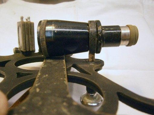
Figure 5: Bent telescope rising piece.
Straightening the micrometer shaft was altogether more complex, as not only was the shaft bent, but the bracket that holds the index was also distorted (Figure 6).

Figure 6: Bent micrometer worm shaft.
A brief account of the micrometer mechanism will perhaps help the reader to appreciate the problem better. The parallel worm lies between two reduced portions of its shaft and the walls of each reduced portion are conical in shape. The parallel parts of the shaft that lie between the conical portions make no contact with the bearings. Only the conical parts do so and, if properly made, by no means a simple task, when assembled all axial and radial play is removed while still allowing the shaft to rotate freely (Figure 7). For an account of making a similar new micrometer shaft and worm, see my post of 6 July, 2009, A Worm Turns.

Figure 7*: Micrometer shaft in its bearings
The bearings form part of what I have chosen to call the swing arm, a brass casting that is held between two trunnions in the form of screws with hardened, conical ends, that allow the arms and the included micrometer worm to swing in and out of engagement with the rack against the pressure of a leaf spring (Figures 8 and 10). Note how the index of the micrometer drum is carried on a slender bracket that is attached to the sides of the front bearing.
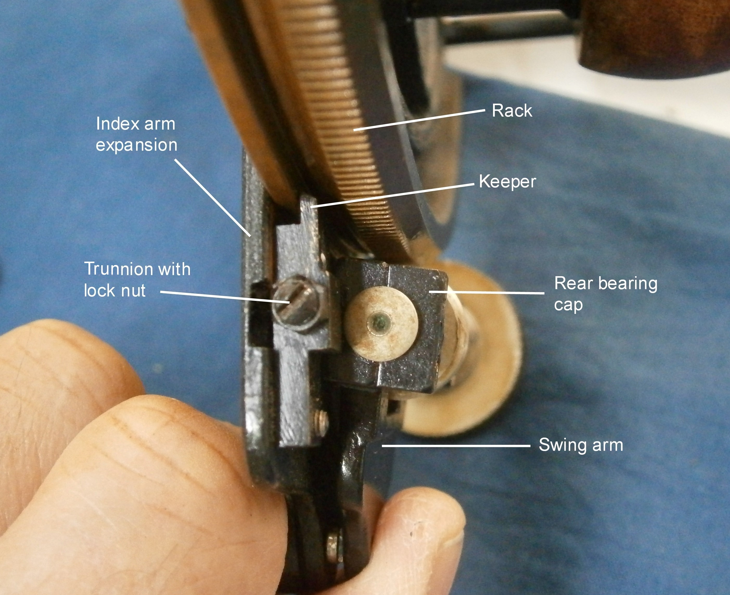
Figure 8*: Swings arm and trunnion.
The trunnions are adjustable to allow all play to be taken up while allowing free rotation. The trunnions are then locked in place by means of lock nuts. The blocks in which they run are extended to form keepers that prevents the index arm from lifting off the frame.
When straightening a bent shaft it is difficult to ensure that one does not end up with two bends in opposite directions, but in this case, the bend took place at the narrow parallel portion of the shaft that is not normally in contact with the bearing and which takes no part in its alignment. Figure 9 shows one way to straighten the shaft to restore its alignment with the worm.

Figure 9: Straightening the shaft under control.
The 15 mm diameter worm is held in an ER collet in the spindle of my milling machine and a 90 degree vee block is held in the machine vice as a guide to alignment. While the shaft rotates slowly, the position of the block is adjusted so that the point of maximum eccentricity is aligned midway between the sides of the bloc, when rotation is stopped and the machine table moved to give the shaft a nudge in the right direction. The shaft is alternately rotated and nudged until no eccentricity can be detected in the part of the shaft that carries the micrometer drum.This of course only guarantees that the drum and the worm are concentric, but these are the important alignments. While some slight eccentricity of the front bearing remained, it was of the order of only 0.03 mm.
The index bracket had taken on a curious shape and in trying to straighten it, it became partially detached from the side of the front bearing. As it had been soft soldered into place, I completed the detachment by heating with a small flame and this allowed me to straighten its slender sides using a combination of vice and punch. T
his then left me the problem of re-attaching it so that the index would be correctly aligned. Figure 10 shows how I did this (note too how this photo shows the trunnions and their mountings clearly).

Figure 10*: Soldering jig.
I first turned up a bush of the same diameter as the micrometer drum to fit in place of the drum, and of a length equal to the combined thickness of the drum plus index. I then bored out one end of the bush to a depth equal to that of the thickness of the index. When in place (Figure 11) the bracket could then be clamped to it in the correct orientation and the arms of the bracket sweated back into place with soft solder.

Figure 11: Soldering jig in place.
Happily, when the micrometer mechanism was re-assembled, everything ran smoothly, but when I next have an auto-collimator out on my surface table I will check for eccentricity errors of the drum. None is visible to the naked eye. In the course of dismantling the index shades for painting and lubrication, the head of the (steel!) screw that prevents the shades mounting shaft from rotating broke off, leaving me with one last task, that of drilling out the broken screw and fitting a new brass one (Figure 12). The process is the same as for drilling out broken legs.
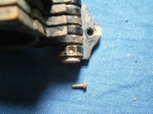
Figure 12: Broken screw and its replacement
After making new mirrors (Posts of 11 February 2009 and 27 March 2011) and clips, all that remained was to take everything apart, clean, strip and respray everything, re-assembling, greasing and oiling where appropriate, and to re-finish the mahogany case (Figures 13 and 14).

Figure 13*: Finished sextant in its case

Figure 14 * Rear face of finished instrument.
If you have enjoyed reading this blog post, you will probably enjoy owning a copy of my book, “The Nautical Sextant“. You may also enjoy reading my book “The Mariner’s Chronometer” Both are available through Amazon, Paradise Cay and Celestaire.
Comments : Leave a Comment »
Categories : Interesting Overhaul Problems
Replacing the Pellicle of an MA1 sextant
8 10 2016This post is preceded by “A Countinho-Pattern Bubble sextant’; “How to Refill C Plath Bubble Artificial Horizon”; “The SOLD KM2 Bubble Sextant”; “C Plath Bubble Horizon Attachment”;“A gummed up AN5851-1 averager”, “Bubble illumination of Mk V and AN 5851 bubble sextants” , ”Refilling Mark V/AN5851 bubble chambers” , ”Overhaul of MkV/An5851 bubble chamber” , ”AN5851-1 : jammed shades carrousel” , ”A Byrd sextant restored” , ”Update on Byrd Aircraft Sextant”, “A nautical sextant bubble horizon” and “Sealing A10 vapour pressure bubble chambers.”
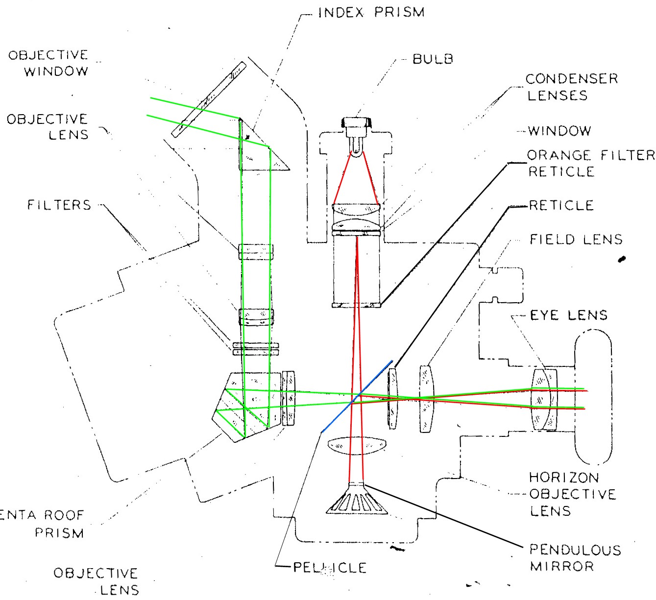
Figure 1: MA 1 light path diagram.
Figure 1 shows the light path diagram for the MA 1 aeronautical sextant click on it to enlarge). Its near relative, the MA 2 uses a spirit level as a horizontal reference, but the MA 1 uses a mirror whose surface is maintained horizontal by a hanging weight damped in fluid. Light from a bulb passes through a condenser lens system, through an orange-coloured reticle, through a thin transparent membrane or pellicle, through an objective lens and then is reflected off the mirror. On its return path it is reflected off the under surface of the pellicle into the eyepiece.
Rays from the observed object pass via the index prism and an objective lens system, are deflected through 90 degrees by a pentaprism and then pass via another reticle into the eye piece in such a way that the black lines of the object reticle, the orange lines of the mirror reticle and the observed object may be in view together. The object is kept in coincidence with the orange reticle, as far as possible in the centre of the field of view, as indicated by the object reticle.
The pellicle was probably made from flexible collodion, a substance based on nitro-cellulose that forms an exceedingly thin film, but which suffers from the disadvantage of being very delicate and prone to distortion and wrinkling if it becomes damp. Forty-odd years after manufacture, the dry nitrogen with which the instrument was filled has often been replaced by air and the dessicator has become saturated with water, so that the image of the orange reticle becomes distorted by wrinkles. While very thin transparent plastic films are now available in the form of food wrap, it seems to me to be much simpler to replace the pellicle by a microscope cover slip. Its thickness is about 0.14 mm and so light is reflected off both surfaces of the glass to give a double image of the horizontal reticle line. This is not necessarily a disadvantage, as it is easier to place an image of a star between lines than it is to superimpose the image upon a single line, though motion of the aircraft is likely to make this a moot point.
There is a method using food wrap and I include it as an appendix.
The first step is to remove the dessicator by withdrawing two countersunk screws circled in white in Figure 2. This makes it slightly easier to remove the left side of the instrument together with the shades mechanism and also allows the dessicant to be refreshed if the granules are pink or white. The end of the dessicator unscrews and the granules can then be tipped out onto a shallow tray and baked in an oven at 120 Celsius for 20 minutes or until they have regained a blue colour.
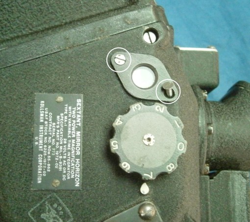
Figure 2: Remove dessicator.
Then the four corner screws are removed as shown in Figure 3. Remove the screws completely before attempting to lift off the side cover. Then lift the rear of the cover a few millimetres and slide the cover backwards for a few millimetres, to avoid fouling the shades mechanism on the frame.
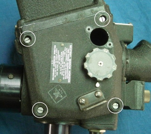
Figure 3: Remove left cover.
This exposes the pellicle on its frame. Removal of two screws allows it to be lifted out for inspection, holding it by its edges (Figure 4).

Figure 4: Remove pellicle frame.
If the pellicle appears to be flat and undamaged, dust particles may be removed by gently blowing dry air on to it or by very light brushing with a soft camel hair brush. If you are ham-handed it is better to leave dust in place rather than risk damage to an intact pellicle. If, however, the pellicle is broken or wrinkled, remove its remains with a finger nail and then clean the front machined surface with ether solvent. It is then a simple matter to place three tiny drops of super glue on the frame and, using tweezers, to glue a microscope cover slip in place (Figure 5). A nicely worded request for a small handful of cover slips is unlikely to be refused at your local medical laboratory. They are perfectly clean as they come from the maker, so try to keep them that way.

Figure 5: Replace pellicle with cover slip.
Figure 6 shows the eyepiece view after replacing the pellicle with a cover slip.
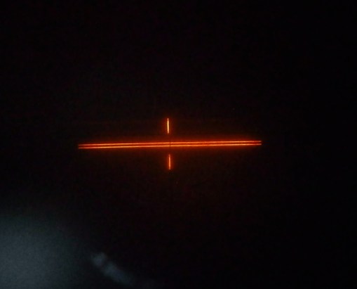
Figure 6: View through eyepiece, using cover slip as semi-reflective mirror.
APPENDIX
Using food film as a pellicle replacement is slightly more difficult:
1) Obtain a circular embroidery frame such as may be had for a very few dollars and stretch a piece of food film (Clingwrap, Gladwrap etc) over it, adjusting the frame until the film is perfectly flat and wrinkle free. Make sure that it is perfectly clean and free from finger marks.
2) After cleaning old pellicle off the frame, place a smear of two-part epoxy adhesive (e.g. Araldite) around the frame, just outside the flat machined area, avoiding placing adhesive on the flat surface itself.
3) Set the frame down on the centre of the film, adding a weight of a few hundred grams to hold it in place until the adhesive dries. Then trim off excess film with sharp nail scissors or the like.
Comments : Leave a Comment »
Categories : Aircraft bubble sextants
Mending broken legs
7 10 2016One of the commoner parts to be broken when sextants are dropped or break loose from their moorings in the case is a leg. Legs are often rather long and slender with a correspondingly small diameter to the screw thread that attaches them to the frame. A typical thread outside diameter would be 4 mm and the core diameter of an M4 thread is a mere 3.3 mm. Usually, the threaded part breaks off, leaving a short stub behind on the leg. This post is mainly about extracting the threaded part from the frame.
Extracting large threads is relatively easy. One just drills a hole approximately down the middle and inserts an “Easy-out”, a hardened tapered tool with a coarse left hand thread cut on it. As it is screwed into the hole (left handed of course) it eventually jams and continued rotation extracts the broken stub. However, the threads used on sextant legs are too small for this to be an option, and more care is needed. Figure 1 shows the starting point, as found in an antique Observator sextant. The thread is M4, with a tapping size of 3.3 mm.
Figure 1: Broken leg as found
Two centre punches are needed, one with a sharp point with an included angle of about 40 degrees, sometimes called a prick punch, and another with a greater included angle, approaching about 90 degrees. Both need to be sharp. Using a strong hand lens the centre of the stub is located (Figure 2) with the prick punch and very light pressure applied, just enough to make a tiny depression.

Figure 2: Marking the centre.
This is checked for centering and if it appears to be off-centre, it is coaxed in the right direction by applying light sideways pressure and then uprighting the punch to apply a little more. If satisfactory, the prick punch is given a light tap to deepen the punch mark. [As an historical aside, this method of “coaxing” marks into their correct position was used by Jesse Ramsden when originating his dividing machines some time before 1777.]
This fine punch mark is then deepened and widened with the other punch (Figure 3), carefully exploring with the tip until you are certain that it is located correctly in the fine mark. Give a light tap at first and then check you are in the right place. Follow up with a heavier tap.

Figure 3: Enlarging the centre punch mark
This larger punch mark now guides a drill, starting with a small diameter (Figure 4). About 1 mm seems to be about the correct size, so that the drill point is guided almost entirely by the walls of the punch mark and not deflected by irregularities in the surface of the stub.

Figure 4: Fine drilling.
A sensitive touch is needed with the drill, as one does not want it to come out on the face of the frame. Happily, there is usually a little space beyond the end of the stub and the drill can be felt breaking through. If you are confident that the drill hole is correctly centred, you follow up with a larger drill, in this case, one of 3 mm and if it still seems to be correctly centred, finish with one at tapping size. If it is off centre, increase the size of drill used until one wall of the tapped hole is reached and then pick out the remnants of the stub. This is most easily done with a tap of the correct size, but a stout scriber will also do the job. Figure 5 shows the final result of doing this.

Figure 5: Female thread liberated.
Preparing the leg is a matter of simple turning, though I imagine it could also be done with a file and hand drill. First the remains of the stub are faced off in the lathe and a hole of the correct tapping size drilled down the leg. This is then tapped and a screw of the correct size inserted until it jams. I generally add a small drop of Loctite to make sure, before cutting off the screw to a suitable length. Figure 6 shows the prepared leg ready to be inserted into the threaded hole in the frame.
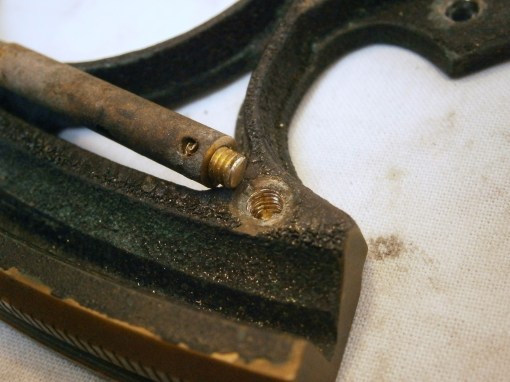
Figure 6: New male thread inserted.
This method of drilling out a broken stub of thread can of course be used elsewhere when restoring instruments, though especial care needs to be used when the thread, say of brass, is stuck in a hole made of a softer metal like aluminium alloy. If the drill drifts off centre it may take the path of least resistance through the softer metal, leaving a mutilated stub and a new hole in the wrong place. This may need some creative bodging to correct…
Comments : Leave a Comment »
Categories : Broken legs

You must be logged in to post a comment.