Previous posts in this category include: “A C19 Sextant Restoration” , “Making a Keystone Sextant Case” , “Restoring a C. Plath Drei Kreis Sextant” , “Heath Curve-bar sextant compared with Plath” , “A Drowned Husun Three Circle Sextant”, ”Troughton and Simms Surveying Sextant” , “A Sextant 210 Years On” , “A fine sextant by Filotecnica Salmoiraghi”, “A British Admiralty Vernier Sextant”, “An Hungarian Sextant via Bulgaria” , “A Half-size Sextant by Hughes and Son” and “A Fine C Plath Vernier Sextant”, “Heath and Co’s Best Vernier Sextant.” and “An Early C19 Ebony Quadrant Restored”.
Recently, I was made the guardian of an exceptional nineteenth century sextant made by Spencer, Browning and Co. The owner, whose father had bought it in an antique shop fifty years previously, did not wish to see it on e-bay, and I am flattered that he took the trouble to send it half-way around the world to me for me to look after.
The firm of Spenser, Browning and Co. has a long history going back even further than Richard Rust, who was apprenticed to his master, possibly a John Rust, for a term of seven years. Rust in turn was apprentice-master to William Spencer, who joined him at the age of about fifteen in 1766, to Samuel Browning in 1768, and to Ebenezer Rust in 1770. Ebenezer was probably Richard Rust’s nephew. Spencer and Browning formed a partnership in 1778 which lasted to 1781 and in 1784 the partnership was reformed by the inclusion of Ebenezer Rust. The members of the partnership were described as “grocers”, which at that time meant “a trader in gross quantities” and included such trades as mathematical instrument makers. Originally trading from 327 Wapping High Street in London, they later moved to 66 Wapping High Street, a site now occupied by modern apartments.
Sam Browning married Spencer’s sister, Catherine, and their sons Richard, William and Samuel were in turn apprenticed to their father. William Spencer and his wife Anne had no children, but their nephews Samuel, John, Anthony and William Spencer were apprenticed to their uncle William. Ebenezer Rust’s son, also Ebenezer, was apprenticed to his father in 1795. With so many family members involved we may surmise that the firm of Spencer Browning and Rust was very successful, as witness to which is the relatively large number of their instruments that survive in museums and collections. Of the original partners, Ebenezer Rust died in 1800, William Spencer in 1810 and Samuel Browning in 1819. Upon the death of the younger Ebenezer in 1838, the firm became Spencer, Browning and Co., which continued to trade until 1870.
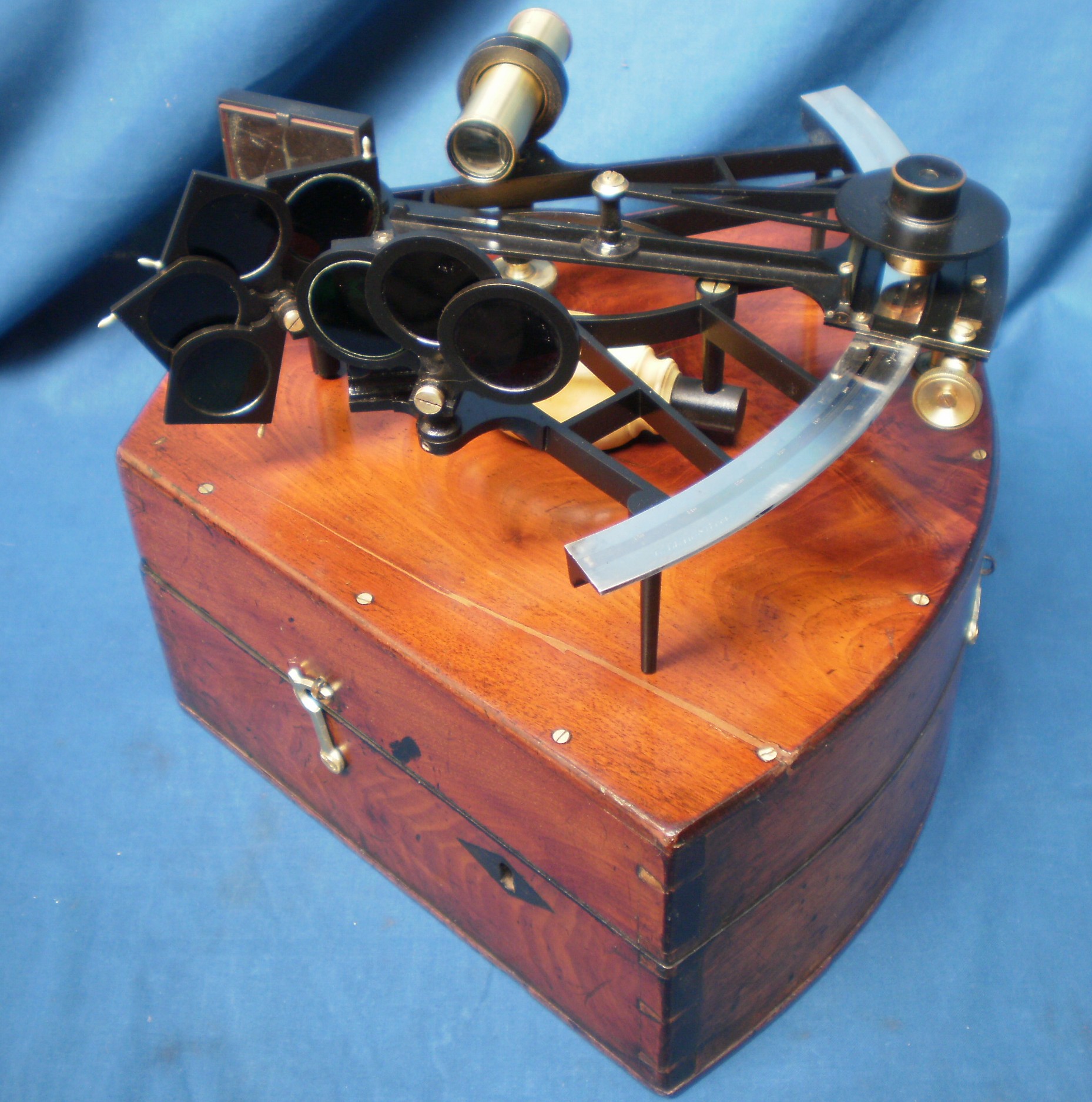
Figure 1: Restored sextant and case.
Thus, the instrument, shown restored in Figure 1, can be placed between 1838 and 1870. Its keystone case, I would suggest, places it in the earlier part of this period, although one with a similar serial number in a collection is provided with the more convenient rectangular case. What is clear is that the sextant, readable to 135 degrees, is a high-end instrument. Immediately obvious (Figure 1) is the handle of ivory and , inside the case, the large kit of telescopes. (You can enlarge all the figures by clicking on them. Return to the text by using the back arrow)
Less obvious is the arc of gold inlaid into a limb of silver (Figures 2 and 3), but in case anyone might be in doubt, the words “Gold in silver” appear at the left end of the limb.
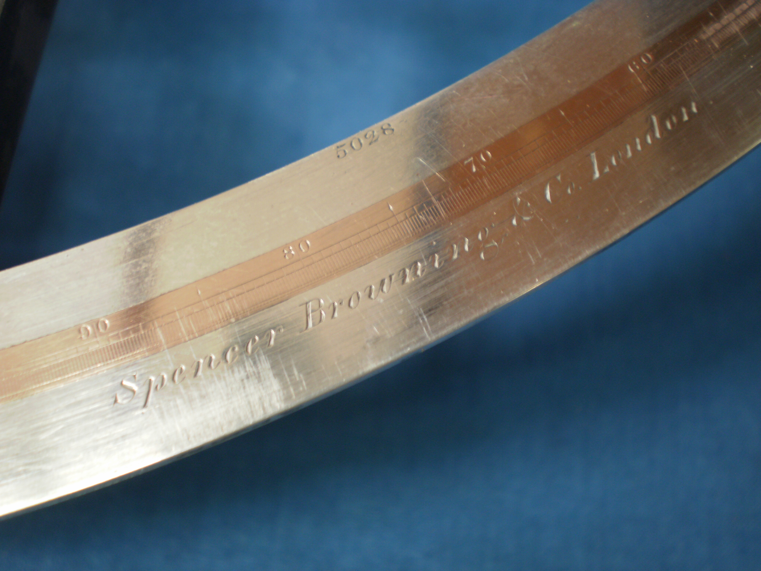
Figure 2: Face of limb and arc.

Figure 3: End view of limb and arc.
The structure of the limb follows eighteenth century practice, as one would expect of a company whose seniors trained at the end of that century and whose successors were their relatives. Usually, a limb of brass was screwed and sweated on to the face of the bronze frame and a dovetailed segmental groove machined in it. A strip of silver would then be hammered into the groove and machined flat (See “A Sextant 210 years on”). The reason for using silver is well-known. The brass of the time was hammered and rolled into sheets and there were frequent hard spots in it which could divert the scriber of the dividing engine. Silver, by contrast, was available in a pure and soft state. The reason for attaching the brass limb to the bronze casting of the frame is less clear. The bronze of the day was perhaps higher in tin content than in later instruments and was sometimes described as “bell metal”, a hard and tenacious metal which would have been very difficult to machine at such a large radius on the sort of lathe likely to be available to instrument makers of the time. It is easy to forget that thee was no powered machinery and lathes had to be turned by hand or foot. It is true that large and rigid lathes were coming into being in the first half of the nineteenth century, but these were to be found in the workshops of steam engine builders and the like. Interested readers can find more details in LTC Rolt’s book “Tools for the Job.” I surmise that attaching the softer brass limb was a means of getting around a machining difficulty.
I have occasionally seen sextants with the usual arc of silver but having a gold vernier. The combination gives improved contrast of the scales, but this is the first time I have seen one which has a gold arc too. As well as perhaps reflecting the wealth of the owner, there is a more practical reason for having a golden arc: gold does not tarnish as does silver and so never needs to be cleaned, with the attendant risk of damaging the almost impossibly fine graduations. Even if polishing does not remove the graduations altogether (and I have seen a sextant in which the arc has been reduced to unreadability for this reason), it tends to round their edges, making it more difficult than usual to read a vernier against them. Figure 4 shows how beautifully sharp the graduations remain. Also visible in this figure at the top left of the limb is the ghost of a screw head, which has been used to attach the limb, its head then being riveted into the limb and machined flush. Sextants with platinum arcs are occasionally seen. Surprising as it might seem, this was at first an economy measure, as it was cheaper than silver in the early nineteenth century, because no use could be found at the time for this relatively chemically un-reactive and difficult-to-work metal.
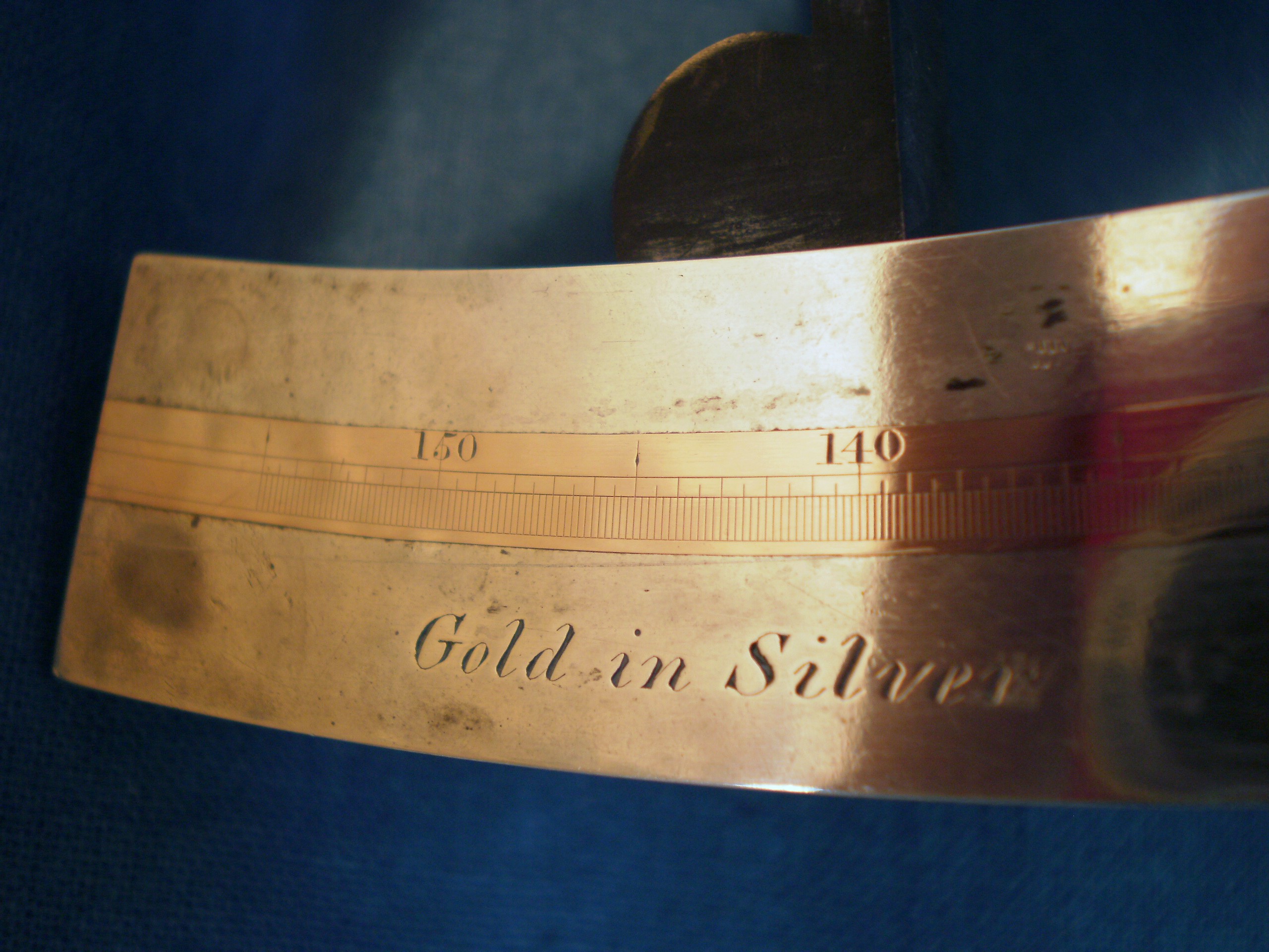
Figure 4: Close-up view of graduations.
Figure 5 shows the index mirror bracket. This uses the familiar three-point bearing for the back of the mirror, and the next figure, Figure 6, shows the clip which holds the mirror to the bracket directly over the points. A screw through the centre of the back of the clip and bearing on the back of the bracket pulls the clip back on to the mirror. In 1772 Peter Dollond claimed to have invented this system. At any rate, he was granted a patent for it, though he may not have invented it, as in the eighteenth century patents were about monopoly rather than originality.

Figure 5: Index mirror bracket.

Figure 6: Index mirror clip.
The shades and the horizon mirror follow a pattern that became quite standard in the first half of the twentieth century. Indeed, the horizon mirror is perhaps remarkable for the absence of the complications that characterize the adjustments of many nineteenth century instruments (Figure 7). It has the three point mounting for the mirror with two adjusting screws to correct for side and index error, with the added refinement of screw caps to protect the screws, one of the requirements for the sextants of British naval cadets in the latter part of the century (they also had to have class A certificates from Kew Observatory).
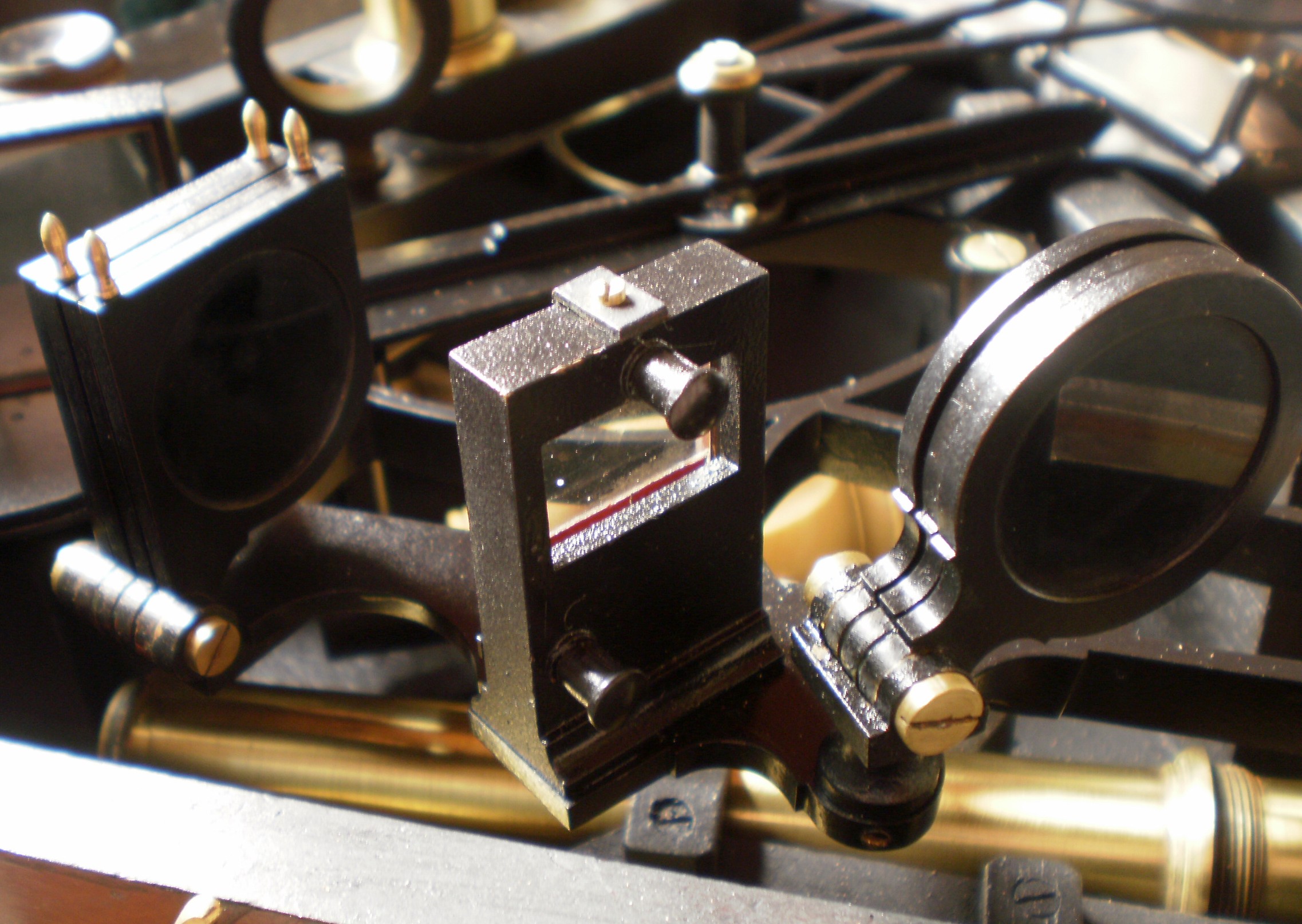
Figure 7: Index mirror and shades.
Figure 8 shows structures in the region of the magnifier. The magnifier itself is a Ramsden compound type. It is not clear to me what purpose was served by the large surrounding disc unless perhaps to cut down glare. Many sextants have a ground-glass diffusing screen, but this one is hinged and can be folded down flat. Engineering students are (or more likely nowadays, were) taught to read a vernier scale by arranging the light to shine along the graduations, but this seems to fail with the sextant, in my hands, since the main scale always looks much darker than the vernier, sometimes to the point of unreadability. I find the scales much easier to read when the light shines across the graduations, but even so I have yet to come across a vernier divided to ten seconds in which I can definitely say which of three or four pairs of lines coincide, even using a x30 microscope with axial illumination. The best I can do is to choose the two pairs of lines which just do not coincide and to choose the middle value between them.
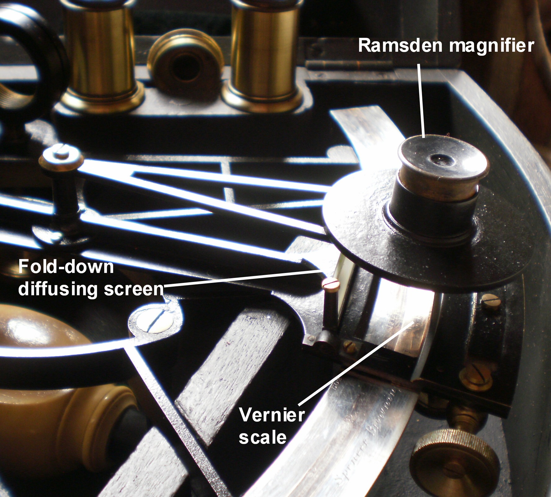
Figure 8: Scale magnifier.
The telescope rising piece and collimation ring, both of conventional form, needed only cleaning and re-greasing, but the same was not true of the index arm. After dismantling it I found that the index arm expansion was bent and twisted, so that the vernier scale could not be brought to lie flush with the arc. This seems to be a common consequence of dropping or bumping the instrument as the cut-outs in the index arm expansion severely weaken it and little force is needed to bend it. Figure 9 shows the tapered gaps quite clearly as well as showing the state of the paintwork before restoration. Tightening of the index arm clamp only made matters worse, so I had to reassemble the clamp and carefully first correct the twist and over-correct the longitudinal bend until the feather edge of the vernier sat squarely on the arc when the clamp was tightened.
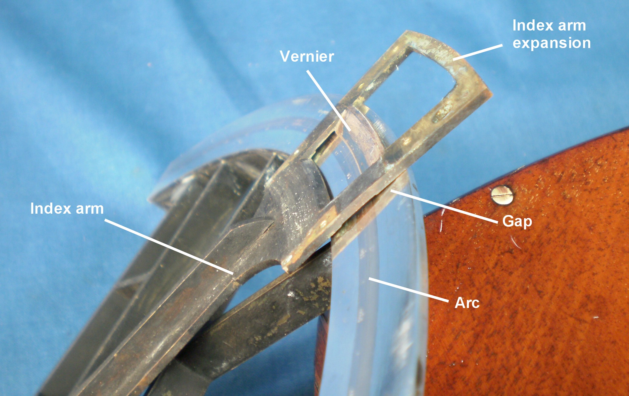
Figure 9: Bent index arm.
Figure 10 shows the index arm clamped, with the fault corrected.

Figure 10: Bent index arm corrected.
The rest of the restoration consisted of the by-now-usual dismantling down to the last screw, cleaning all the parts, polishing and lacquering screw heads and other brass parts usually left bright and spraying other parts with black lacquer to reproduce as closely as possible the original finish. The case seemed to have suffered from modern central heating, which tends to dry out wood and cause it to shrink and crack where it is restrained by screws. The large shrinkage crack in the top is shown in the un-restored case in Figure 11. I decided to fill the crack with mahogany paste, but if it had been much larger, I would have been tempted to remove the top, complete the crack with a saw cut, plane the edges and glue in a strip of approximately matching wood. This process applied to the base of a sextant case will be shown in my next post.
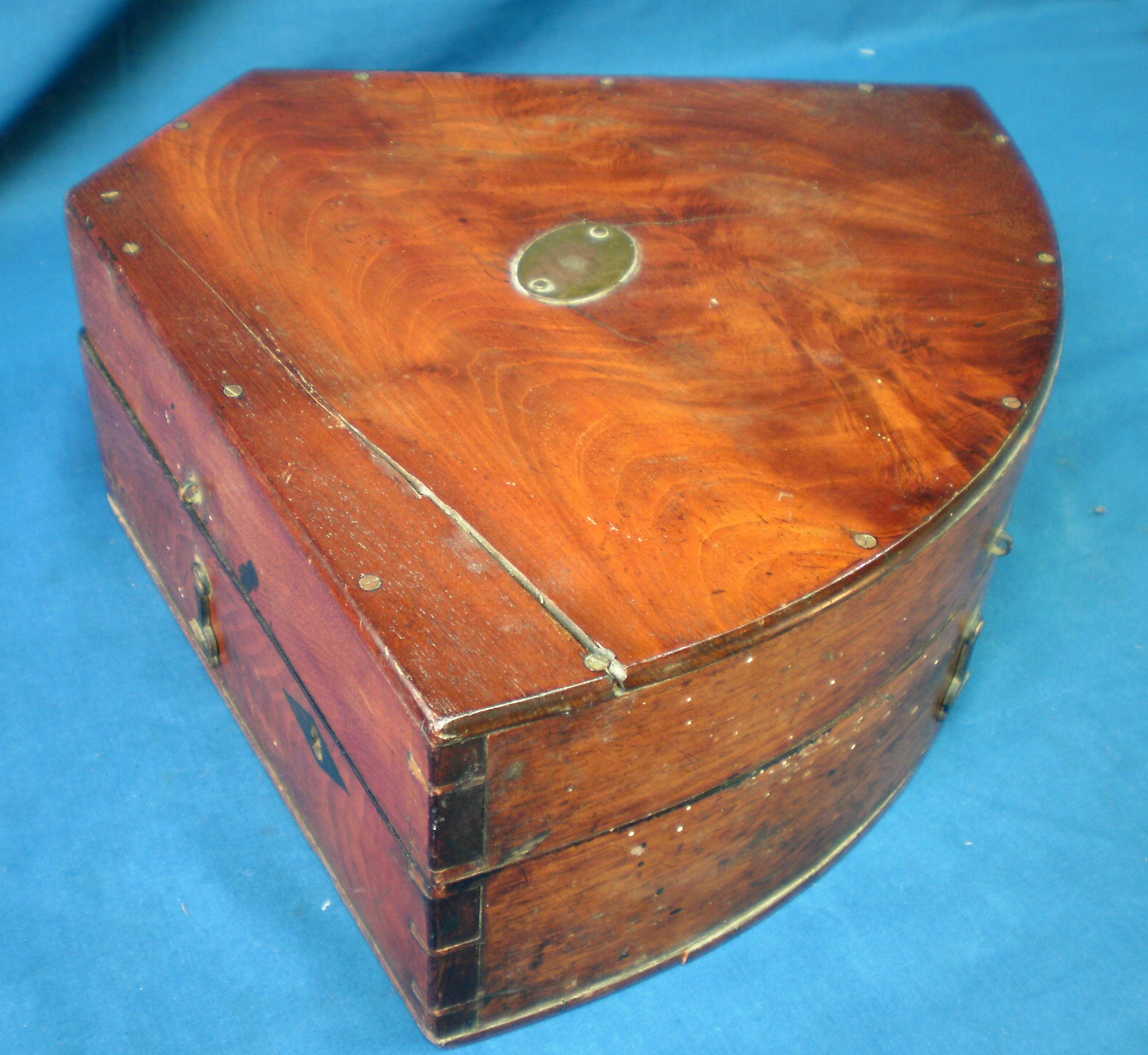
Figure 11: Un-restored case.
Happily, what appeared at first sight to be worm holes in the bow front of the case turned out to be fly deposits (flies alight on surfaces after feeding and regurgitate their fluid meal, prior to sucking it up again…). The French polish on the sides was much battered and dented, and would have required major repairs, but I felt it worthwhile to strip the top and re-polish it to show off the grain of the wood. to better effect.
The interior of the case too was battered and some of the blocks for retaining the telescopes and sextant were absent, so I made this good and renewed all the felts. The original interior finish in matt black paint was in poor condition, so I repainted it as close to the old finish as possible (Figure 12). The lacquer on the telescopes and sighting tube was flaking and decayed so this too I renewed. I imagine some antique dealers might be horrified at this loss of “valuable patina”, but in my view, the instruments do not need it to be placed in their era. No one, after all, objects to antique cars being refinished, indeed they are much less valuable in a rusty and battered state.
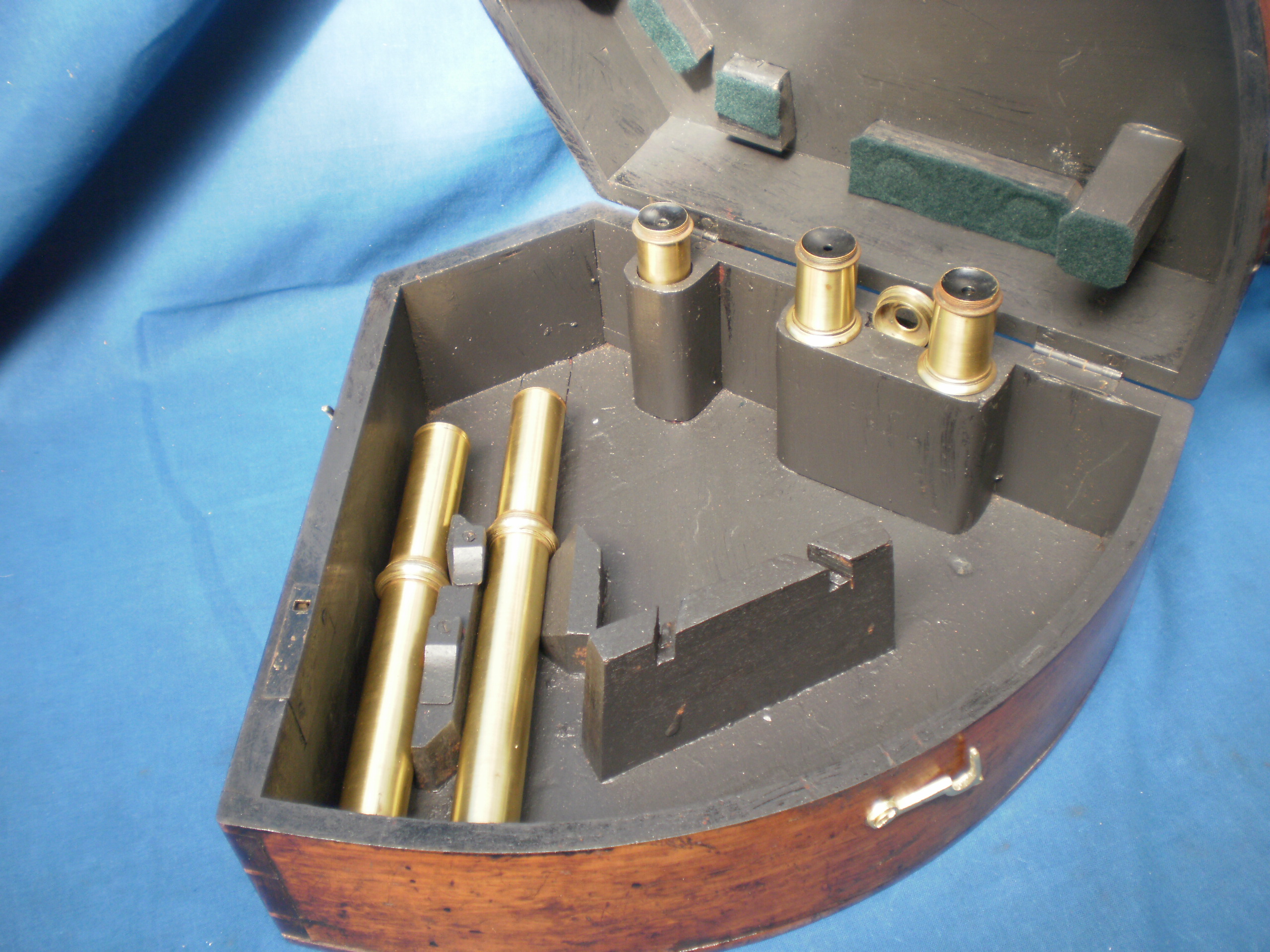
Figure 12: Interior of case with telescopes.
The rule with telescope kits seems to have been that “more is better”. There is a 4 x 18 mm Galilean or “star” telescope, a 6 x 18 mm inverting telescope with an additional eyepiece giving a x 10 magnification, a zero magnification sighting tube and a 18 x 18 mm telescope with additional lenses to give an erect image. It is difficult to see what practical the purpose the latter telescope served except perhaps to add prestige to the whole kit. The kit is completed by a single deep red eyepiece shade that screws on to any of the eye pieces. The star telescope would probably have received the most use, by day or night, while the higher magnifications would have been reserved for use with an artificial horizon on land in remote places to check the rate of the chronometers. The 6 x 18 inverting scope may have been used in calm seas for sun sights, while the sighting tube would be reserved for rough conditions and for taking angles between shore objects.
If readers have comments, or corrections, or have some question about this instrument, I am happy to receive them and to comment in turn when appropriate.

You must be logged in to post a comment.