Heath Curve-bar sextant compared with Plath

28 01 2010

The preceding posts covers “A C19 Sextant Restoration” , “Making a Keystone Sextant Case” and “Restoring a C. Plath Drei Kreis Sextant” .

Shortly after I completed the restoration of a Plath Drei Kreis (three circle) sextant I was given the opportunity to restore an English sextant from the same period, a Heath Curve-bar sextant, so called because the frame appears to be made up of thin, curved bars (but is in fact a bronze casting). This one received a certificate from Kew Observatory in 1898 and in addition to being named “Heath and Co., Ltd.,  Crayford, London S.E.” also carried the owner’s name in full engraved in on the limb. As was usual in 19th century instruments, the maker’s name was in copperplate script rather than in the later type.

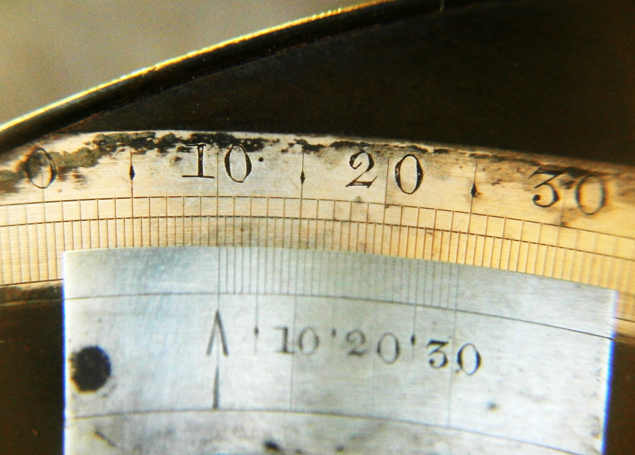
Like the Drei Kreis, the arc is divided to read to 10 seconds with the vernier and the radius of the arc is much the same at about 165 mm.

Apart from there being widespread verdigris, this sextant posed no particular problems as everything was intact, with no missing parts, so I will not bore you with the details of restoration. It was a simple matter of dismantling it to its parts, cleaning off verdigris, polishing screw heads and re-lacquering. The case needed only filling of a large shrinkage crack in the bottom and cleaning up the handle and latches. Unfortunately, at some time the arc had been polished, so the divisions are in places rather hard to read. While some nineteenth century sextants were chemically blackened, I found traces of black lacquer on the little caps that cover the adjusting screws. The next photo shows the instrument cleaned and reassembled while I waited for the owner’s instructions about re-lacquering. 

This photo shows the finished article:


 I thought this an ideal opportunity to compare an English with a German vernier sextant of approximately the same period, at the turn of the twentieth century.

In the preceding post I mentioned the complication of the tangent screw mechanism in the German sextant. In the Heath instrument, it is perfectly conventional and typical of a mechanism that seems to have served makers and navigators well for over a hundred years.

In the photo above, the sliding block moves in a curved slide formed by a cut-out in the index arm expansion. The floor of the slide is formed, as in the German sextant,  by a plate that is screwed on to the front of the index arm. The end of the clamp screw bears on a small plate to which is attached the clamp leaf spring. The tangent screw is held captive on the index arm by a bearing. The tangent screw has the familiar squared end, and the knurled knob is attached over the square by a central screw which allows the bearing to be adjusted to remove end play. The squared end prevents rotational forces from being applied to loosen the screw. The sliding block is held against the floor of the slide by a leaf spring, seen in the next photo, of the front of the index arm expansion. The screw that passes through the leaf spring holds the nut on to the sliding block. This spring has the same function as the leaf spring on the rear of the sliding block of the German instrument.

The nut is split. This allows the nut to spring inwards and to grip the tangent screw thread flexibly and remove lost motion between the screw and the nut. When the clamp is tightened, the sliding block is held immobile on the limb and when the tangent screw is turned, the index arm is caused to move via the screw bearing.

While the German arrangement is free from backlash when in good adjustment, if there is any stickiness in the slide, it has the annoying feature of moving in one direction, but not returning by means of the spring pressure. In the other arrangement, if the fit between the tangent screw and the nut is not good, due, say, to wear in the screw, or if the bearing is out of adjustment, then there is backlash in both directions. In both types, if the slide is sticky, movement may be uncertain and jerky. In my view, each defect is as bad as the other, but the English mechanism has the merit of simplicity.

In every edition of his work “Wrinkles in Practical Navigation” (and it ran to 21 editions ) Captain Squire Thornton Lecky wrote “An indispensable condition in a sextant is regidity; flexure is fatal…”, so I thought to make a quick comparison of the two sextants, using the crude set up shown in the next photo. The middle 100 mm of the limb is held clamped firmly in a vice and a dial  indicator, reading in 100ths of a millimetre bears against the end of the index arm bearing. A force of one kilogramme is applied to the index mirror by means of an old  kitchen scale and the amount of deflection read off the dial indicator.

Though the German sextant at 1.5 kg weighed about 250 G  more than the English one, there was little difference in the amount of deflection, about 0.6 mm. Interestingly, two mid-nineteenth century English quadrants of radii 20 mm greater and of about the same weight, deflected significantly less at 0.5 mm for a Spencer, Browning and Co., and 0.4 mm for a Crichton. Late twentieth century die-cast aluminium alloy instruments typically deflected about 0.12 to 0.15 mm in this set-up and bronze-framed ones somewhat more. Allowance must of course be made for the smaller radii of the modern instruments, but even so, the superior rigidity of alloy instruments is clear. Neverthless, right to the end some buyers expressed a preference for the heavier, more expensive but less rigid bronze instruments.


Restoring a C. Plath Drei Kreis sextant

24 01 2010

The preceding posts covers “A C19 Sextant Restoration” and “Making a Keystone Sextant Case”

On Christmas Eve of 1974, The small city of Darwin in Northern Australia was struck by Cyclone Tracy, a very compact and intense cyclone with winds gusting to well over 220 kph (140 mph). Eighty percent of the houses in Darwin were totally destroyed. One of the casualties of the destruction was a sextant that in the aftermath found its way into a trunk with several other sextants and theodolites. The trunk was sold at auction for $20, the sextant was passed to a neighbour, a retired merchant sea captain, and he in turn recently passed it on to me. Such generosity must be very rare.

The sextant had escaped major damage. Though some screws were bent or missing, they could easily be repaired or replaced. Mild corrrosion with verdigris was  present, but the frame and index arm had been carefully cleaned without polishing the arc, which was in good condition. Fortunately, in the bottom of the trunk were a sighting tube and  two telescopes. The inverting ‘scope was missing  the objective lens, but my friend in Darwin went back to his neighbour’s trunk and found it in a corner. It was intact, but the balsam between the two parts of the achromatic lens had perished and the lens was unusable in that state. Apparently, it was this that had saved it from being converted into an air-rifle sight.

The next picture shows the sextant as I received it. The bottom screw that attaches the handle was missing and the clamp screw was bent. The lacquer on the telescope tubes had deteriorated to a powdery and patchy brown and the draw tube of the inverting telescope had seized completely. The clamp spring was absent and one of the dowel pins that held it in place was damaged. One of the legs had been replaced by an odd leg. The ground glass diffuser screen above the vernier scale had disappeared. There was, of course, no case, so I felt very lucky to have a complete kit of telescopes and sighting tube.

The famous name “C Plath, Hamburg” was clearly visible on the middle of the limb, and after a little cleaning of the bronze at the right hand end I found  the original tiny Plath logo of a little stick man with a sextant. The “S” is the inspection mark of “Seewarte” or naval observatory. Later, this became “D.S.” for “Deutsche Seewarte” or German Naval Observatory, some time after the formation of the German state in 1871.

Less easy to see was the serial number 5499 on the silver of the arc. The arc is divided from  – 5 to +157 degrees, but the scale is usable up to only 138 degrees 30 minutes,  so that although it was sold as the Drei Kreis (“three circle”) quintant, it falls a few degrees short of 144. The serial number places it a little before 1910 in date, on the basis that Plath made an average of about 320 sextants a year between 1910 and 1925.  The arc of about 175 mm radius is divided to 10 minutes, with the vernier allowing reading to 10 seconds, in principle if not perhaps in practice. Apart from the rather complex tangent screw mechanism, the construction of the sextant is perfectly conventional.  The next photo shows the rear view of the sextant as received.

The next step was to dismantle the instrument to its component parts, clean them in a solution of 50 percent household ammonia with washing up liquid added, rinse, dry and apply masking tape as in the next photo, prior to spraying them with black lacquer.  Although antique sextants are often found with all paint removed and the “brass”  (in fact, bronze) polished to a shine, they were never sold this way. Most often they were painted or lacquered black, or, with earlier ones, chemically browned or blackened. If the silver scale is unreadable owing to tarnish, it usually yields to the diluted ammonia and gentle rubbing with the pad of a thumb. On no account should it be polished, as the markings are very shallow and can be obliterated completely by vigorous polishing. I have one 1920s sextant in which only the numerals remain and am currently restoring one in which the markings over about 20 degrees of the scale are very faint.

Here are the parts looking distinctly refreshed.

I had to make a new leg and this slightly un-sharp photo shows the turning in progress to make the rather slender, tapered leg. Once parted off, a thread then had to be cut on the wider end. Fortunately, all the threads are metric ones.

Although the threads are standard, some of the screw heads are not, so I had to make a new screw to attach the handle. This photo shows it being parted off from the parent 12 mm brass bar.

The clamp screw was bent, but I was able to persuade it back to straightness. The tangent screw mechanism is rather complicated when compared to the standard nineteenth and early twentieth century arrangement, and I hope the next two photographs will help to make its workings clearer. It came into my hands just too late to be included in the print edition of my book, now in preparation.

The clamp is a thin slab of brass that is retained in the sliding block by two dowel pins that allow it some up and down movement, opposed by the leaf spring (ground to shape from a piece of clock spring and soft soldered to the clamp). The clamp screw locks it and the sliding block to the lower edge of the limb. The sliding block is hollow and contains a strong helical spring and its guide, the latter projecting from one end of the block. The other end is split and tapped for the tangent screw. A tongue, which is attached to the underside of the index arm expansion by a screw, is sandwiched between the tip of the tangent screw and a bronze block on the end of the guide. Two screws can be tightened to close the split in the sliding block a little, to ensure a snug fit of the tangent screw.  The sliding block is guided by two curved edges machined in the index arm expansion and is prevented from lifting away from these edges and the underlying surface by the sliding block spring, itself attached to an elbow bracket.

When the clamp screw is tightened, the sliding block is locked to the limb and when the tangent screw is tightened, it moves the tongue and the index arm to which it is attached. When it is slackened, the helical spring moves the index arm in the opposite direction. The two screws that are intended to remove backlash (lost motion) from the tangent screw are unnecessary because the opposition from the helical spring does this. They were a nuisance as far as I was concerned because they both lost their heads when I was trying to remove them and needed about half an hour’s work to drill them out and re-tap forslightly larger screws, which I  had to make from scratch. When a spring-opposed mechanism like this works, it is a pleasure to use, but dirt or a breakdown in lubrication can easily cause it to fail to return in one direction, and this is very annoying.

The rise and fall mechanism for the telescope is conventional:

Having overcome these various obstacles, it was time to reassemble the instrument and adjust the mirrors to ensure they were square to the plane of the arc and, when the scale reads zero, that they were parallel to each other. The paintwork is not quite as shiny as this flash photograph seems to suggest.

This still left the inverting telescope, with its seized draw tube and damaged objective lens. I tried various combinations of spirituous chemicals, releasing compound, heat and cold, but could not persuade the rather thin-walled tubes to release their grip on each other. Vigorous twisting was of course out of the question. In the end, I removed all the optics, pressed out the various light stops and machined a steel slug that fitted snuggly in the wider tube. I then used my larger lathe as a press jack to push out the narrower tube. In the next photograph, the tube is held loosely in the chuck against the shoulder and the steel rod held in the drill chuck is being pressed against the slug, which is out of sight inside the tube. It worked like magic.

The objective lens was even more of a problem, as it was swaged into a little brass cell. Swaging means that a lip of metal is bent over the lens to hold it in a recess in the mounting, and often the only way to get the lens out is to somehow hold the mounting in the lathe and carefully turn away the swaged metal. I managed to do this with only minimal damage to the edge of the lens, and still had enough of the mounting left to make replacement possible. Replacement lenses of the correct focal length and diameter are very hard to come by, so this was a relief.  Once the lens was out, I heated it slowly in a pan of water and, just short of boiling point, was able to slip the two components apart. A little xylene, in which Canada balsam is soluble, cleaned up the two part-lenses and I recemented them with Ultra Clear Araldite, rather than the now-obsolete Canada balsam or one of its very expensive modern replacements. I also used a tiny smear of the same adhesive to remount the lens in its cell. The telescope now gives a very clear view. The next photo shows the rear view of the sextant with restored telescopes, new adjusting pick and a tiny screw driver made from scraps of silver steel, brass and mahogany. The brush is C19 English, but does not seem out of place with this German instrument.

Some woodwork came next. Although I am slow at making dovetails, I can now do so without disaster. The sextant was supplied originally in a box with machine-made comb corner joints, but dovetails with narrow pins are also in period. These can just be seen in the next photo, which shows the interior fittings too. The wood is Sapele (Entandrophragma cylindricum), an African hardwood that closely resembles mahogany.

The photo following shows the instrument and its accessories in place:

The final photograph shows the exterior of the case. I don’t know what contemporary latches and handles would have looked like, so have copied English hook latches of the same period and made a handle that I hope looks slightly Germanic. It is made of five pieces of 6 mm  brass rod silver soldered into a whole. I used French polish for the final finish. I can recommend Zinsser Bulls Eye French polish. It is easy and quick to apply, and an amateur like me can get a good finish with it.

Do let me know if you would like more details of this or any other sextant I have covered on this blog.

If you have enjoyed this post, you might enjoy my book, now in print and available from the publishers or through amazon.com


A Box Sextant

7 01 2010

All figures may enlarged by clicking on them. Use the back arrow to return to the text.

For a sextant enthusiast, to own a box sextant after handling  full sized instruments gives a lot of pleasure. These dainty and ingenious little instruments, measuring only 75 mm in diameter, can be slipped into a pocket, but be quickly brought out to make a reading with a precision of around an arc-minute. They are equipped with shades that allow sun and moon observations and some models come with a small telescope. They are especially handy for taking horizontal angles on land.

Unfortunately, there are many so-called reproductions on the market, and it may not be easy for the inexperienced to distinguish them from the genuine article. One should look for fine, usually straight  knurling on the adjusting knobs, crisp edges to the index arm and magnifier arm, sharp corners on the bracket that holds the latter, smooth, ground edges to the mirrors and sweet operation of the various adjustments. A bright sky should just be visible through the darkest shade (usually red) and should not be visible at all when used in combination with the second shade (usually blue). The two together should allow comfortable viewing of the full sun.

The scale is usually divided on silver, each degree being divided into halves, with a vernier reading to one minute. The arc radius is about 46 mm. Look for crisp regular engraving of the numerals (Figure 1) rather than the uneven, stamped numbering with rounded edges often seen in  reproductions. The numbering on the vernier usually omits the fives, and a scale with crowded numerals reading 5, 10, 15 etc is quite likely to be a fake. The scale is read from the centre of the index arm, the opposite of a nautical sextant, which is read towards the centre.

Scales 001

Figure 1: Scales of genuine antique.

A maker’s name  may be of little help. There must be thousands of so-called “Stanley” and “Kelvin-Hughes” instruments around, the latter usually dated 1918, nearly thirty years before  the real company came into being. Stanley was a highly respected firm of instrument makers and suppliers, founded in 1853 and trading well into the second half of the twentieth century. Older instruments are engraved “Stanley, London” in beautiful copperplate, though they were probably made (and later labelled) by Heath and Co, with whom Stanley eventually merged in 1926. There are box sextants bearing the name of Elliott Brothers and many other nineteenth century instrument makers and most of these are genuine, but it is important to look at the general workmanship as well as the name. Stanley is the name that has been most abused.

The second photo shows a genuine box sextant by Stanley, alonside its big brother from the same period, a vernier sextant of eight inches radius by Crichton of London, dated to about 1850. The lid unscrews to expose the controls, and is screwed on to the base to act as a handle in use.


The next photo shows the underside of the browned bronze base of the instrument. The nib is used to slide the cover aside. This opens the slot through which shades emerge when not in use, as will be seen in a later picture.

Figure 3: Base.

The general view below shows some of the main features. Rotating the control knob moves the index arm and the vernier over the scale while rotating the index mirror. Note the fine knurling and the crisp edges of the pin holes in the central screw. The magnifierarm, its bracket and the index arm also have crisp edges and the screw slots are narrow, the screw heads polished. Sliding the nib brings the peephole into position and a knurled screw is provided above the peephole to attach the telescope when it formed part of the kit (in some makes, the telescope screwed into the hole). Next to this screw is the mirror-adjusting tool, which screws into place. The levers for bringing the shades into and out of position are to the bottom left of the photo. When they are not in position, they project through the slot described in the preceding paragraph. At the top end of the scale can be seen the two square-headed screws which are used to adjust out side error.

The next photograph shows many of these features from a different viewpoint, that also shows the window opposite the peephole and the head of the screw used to adjust for index error.

For those of you who dare not take their instruments apart, in the next picture I have done it for you, by removing three screws from the periphery of the base plate. The shades are raised out of the way. In use, the head of a limit screw ensures their correct position. The index mirror, its bracket and keeper are mounted on a bearing and are rotated by the toothed sector or rack by means of the control pinion, the business end of the control knob. The horizon mirror sits on a base that can be rocked by means of two spring loaded screws to remove side error and the sub-base below it can be rotated by a further spring loaded screw to remove index error.

The next picture shows another view of the interior to show more details of the horizon mirror arrangement.

Thanks to the kindness of Bill Whiteley, I am now (October 2013) able to add a few sentences about the origins of the box sextant.

A memoir of a meeting appeared in The New Monthly Magazine, Vol 24  1828, of “…the late James Allan mathematical instrument maker in London, who died in the year 1821, compiled by the late Rev. Thomas Macfarlane, minister of Edinkillie, with an introductory letter by Sir Thomas Dick Lauder, Bart. Mr Allan was a native of the parish of Edinkillie, who procured to himself a considerable portion of fame by the discovery of several simple, but most accurate methods of graduating mathematical instruments. The pocket sextant, which gained him the prize and encouragement of the Society of Arts of London, was exhibited on the table of the institution at this meeting. It now belongs to Sir Thomas Dick Lauder.”

 A box sextant presented by the 4th Duke of Gordon to his son in 1813, signed by Allan, is now in the Royal Engineers Museum. This gives us a date before which the instruments were being made.
 
In Nov 1800 James Allan is a shopman (?foreman) lately in the employ of the famous Jessie Ramsden receiving a legacy from Mr Ramsden of twenty pounds. It seems that Allan remained at the Piccadilly workshop, (which had been inherited by Matthew Berge from  Jessie Ramsden,) and was in a position to operate independently. In Nov 1809 he presented to the Royal Society of Arts an improvement on the dividing machine created in 1775 by his former employer Jessie Ramsden. Meantime Berge had amongst other matters, been actively miniaturising the moderately short-lived bridge sextant an instrument which in all probability involved the attention of James Allan.
 There currently exists no firm date for Allan’s creation of his box sextant, However we might assume it to be around the time of his improvements to the dividing machine.
I hope to be able to add a little more about the origins of the box sextant when Bill has had a chance to trawl through the Proceedings of the Royal Society of Arts in the British Library.
12 November 2016: Richard Paselk , Professor emeritus at Humbolt University has kindly just send me this link describing some more of the history of the box sextant: http://www2.humboldt.edu/scimus/AvH_HSU_Centenial%20Exhibit/Box_Sextant/BoxSextant.htm 

Finally, this picture, showing the instrument in use, gives another impression of its size.

If you enjoyed reading this post or found it helpful, do let me know and if you have a “doubtful instrument” I will be happy to view a photo and advise.