LAND USE CONVERSION OF MARK IX BUBBLE SEXTANT
A few years ago, I bought a Mark IX bubble sextant for parts from a local auction web site. I had vaguely noted an excrescence had been added to the top, and when it arrived I found that it contained a ninety degree prism. The bubble unit had been removed and in its place was a half-silvered mirror angled at 45 degrees. Someone seemed to have attempted a conversion so that the sextant could be used at sea, using the natural horizon. This in itself is not a bad idea, as the Mark IX series of bubble sextants represents a cheap way of getting an instrument with a digital read out, as shown in Figure 1.

The index mirror is rotated in steps of 10 degrees(actually 5 degrees but the light ray is deflected through 10) by depressing the knob and rotating it, when on releasing it it clicks into the selected value. Pushing up the 5 degree knob adds five degrees rotation to the ray deflection. The fine adjustment knob adds up to 8 degrees fifty minutes to the value set by the 10 degree knob.
Upon further exploration of the excrescence at the top it turned out to contain a right angle prism to divert light entering it directly downwards into the instrument. A variable polaroid filter can be swung to filter the incoming light. I suspect the fitting was canabalised from something like a WWII drift meter. A half-silvered mirror with a silvered aperture of only 18 x 7.5 mm diverted the down-coming rays into the eye hole, joining the rays from the observed body, as in a normal sextant.
Figure 2 shows the interior of the sextant. The gearbox, as well as counting off the degrees and minutes, also rotates the index mirror. The shades control allows seven combinations of three shades of increasing total density

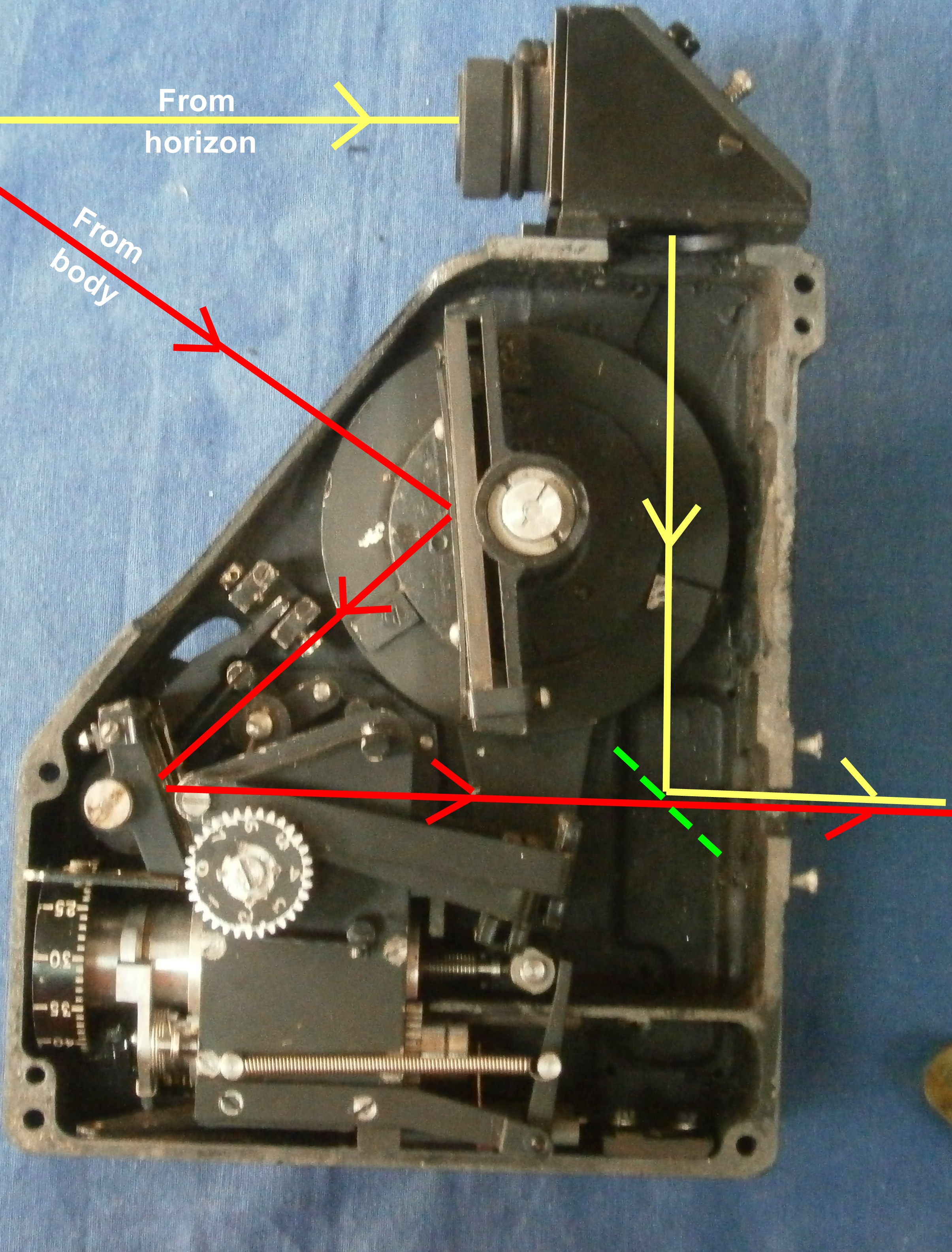
Figure 3 shows the light path of the conversion. Horizon rays are shown yellow, body rays are shown red and the mirror as dashed green.
It is not my intention to provide detailed instructions on replicating this instrument layout, as much will depend on the skills and workshop resources of the reader. However, a few details may help.
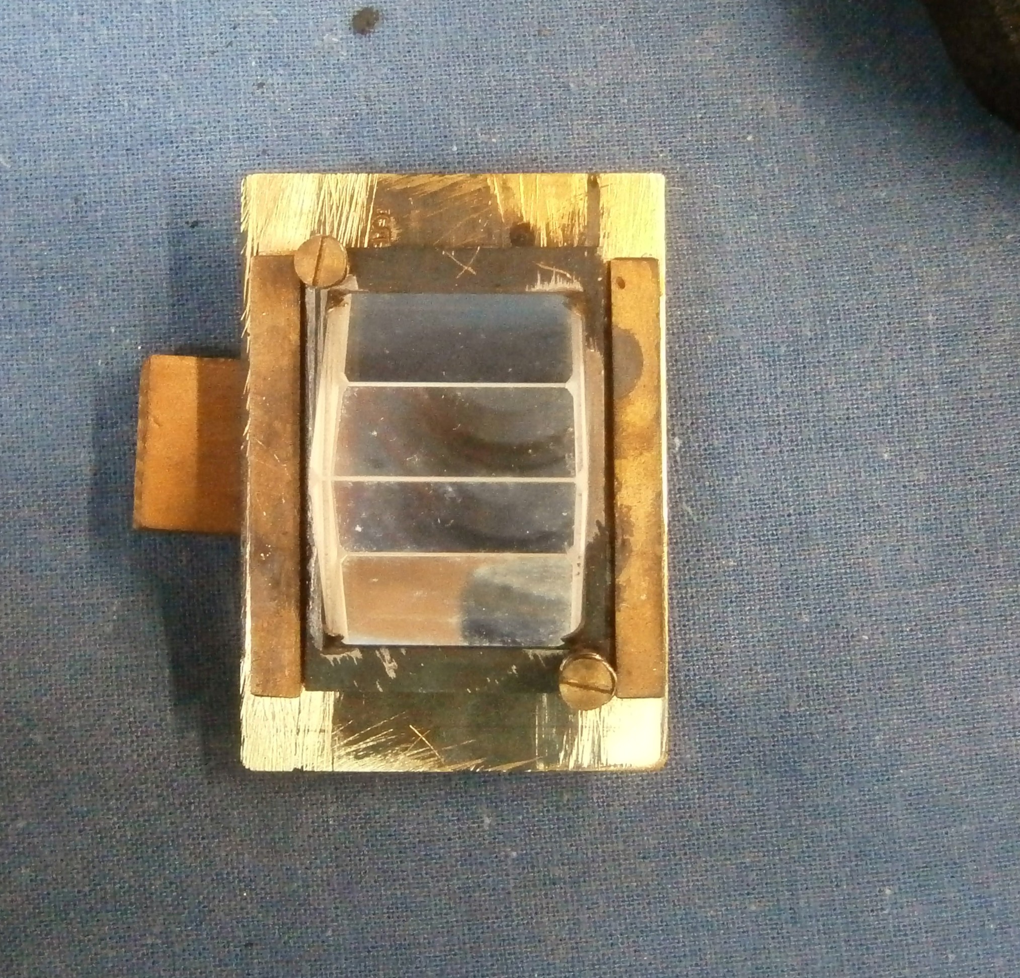
Figure 4 shows the prism mounting from the side. The prism is cemented to a back plate which is held against three points by two springs. The three points are a fixed nipple and two screws for adjusting index and side error.
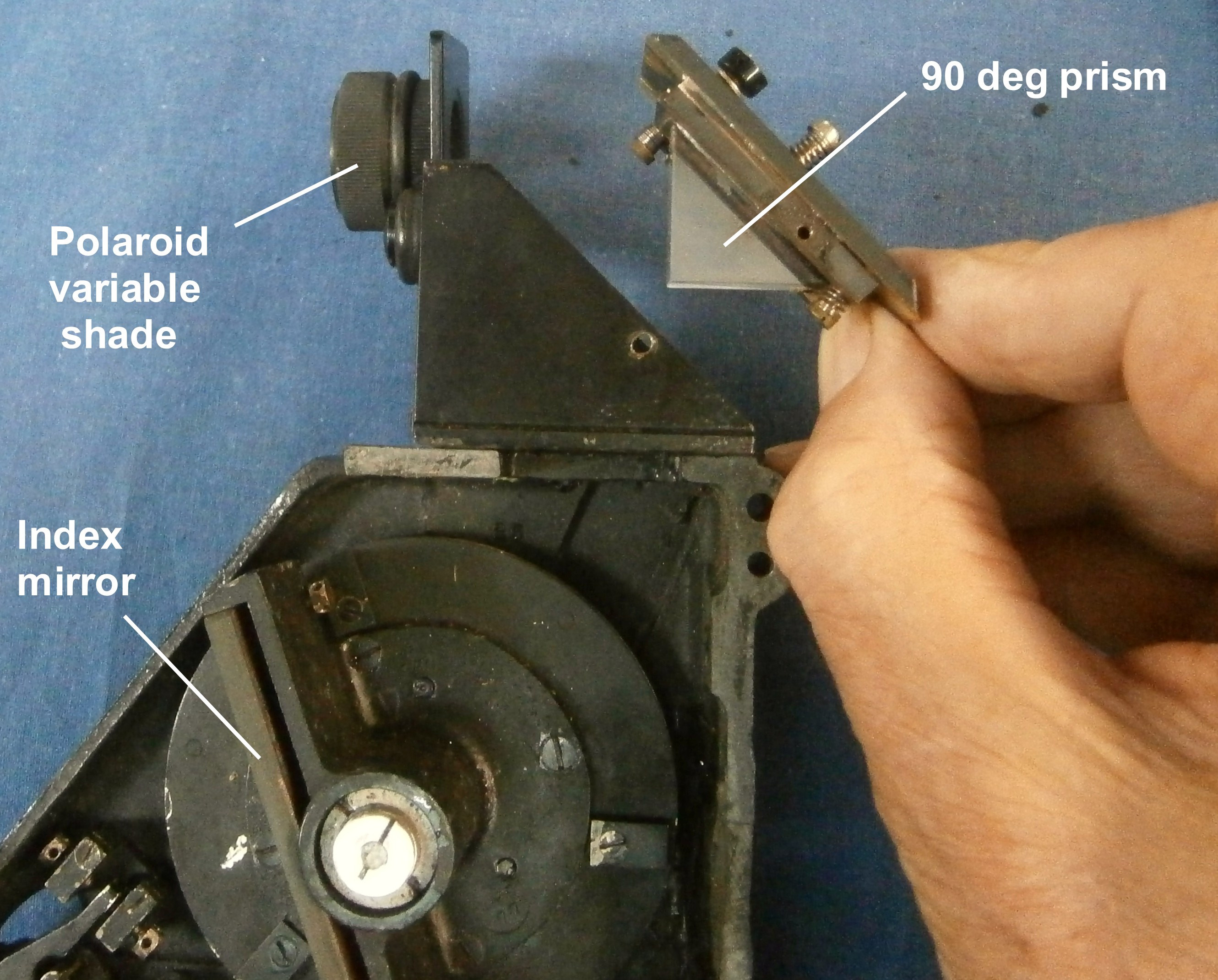
Figure 5 shows that the prism backplate lies between two guide rails, soldered to a further plate which forms the rear of the mounting and which is threaded for the adjusting screws.
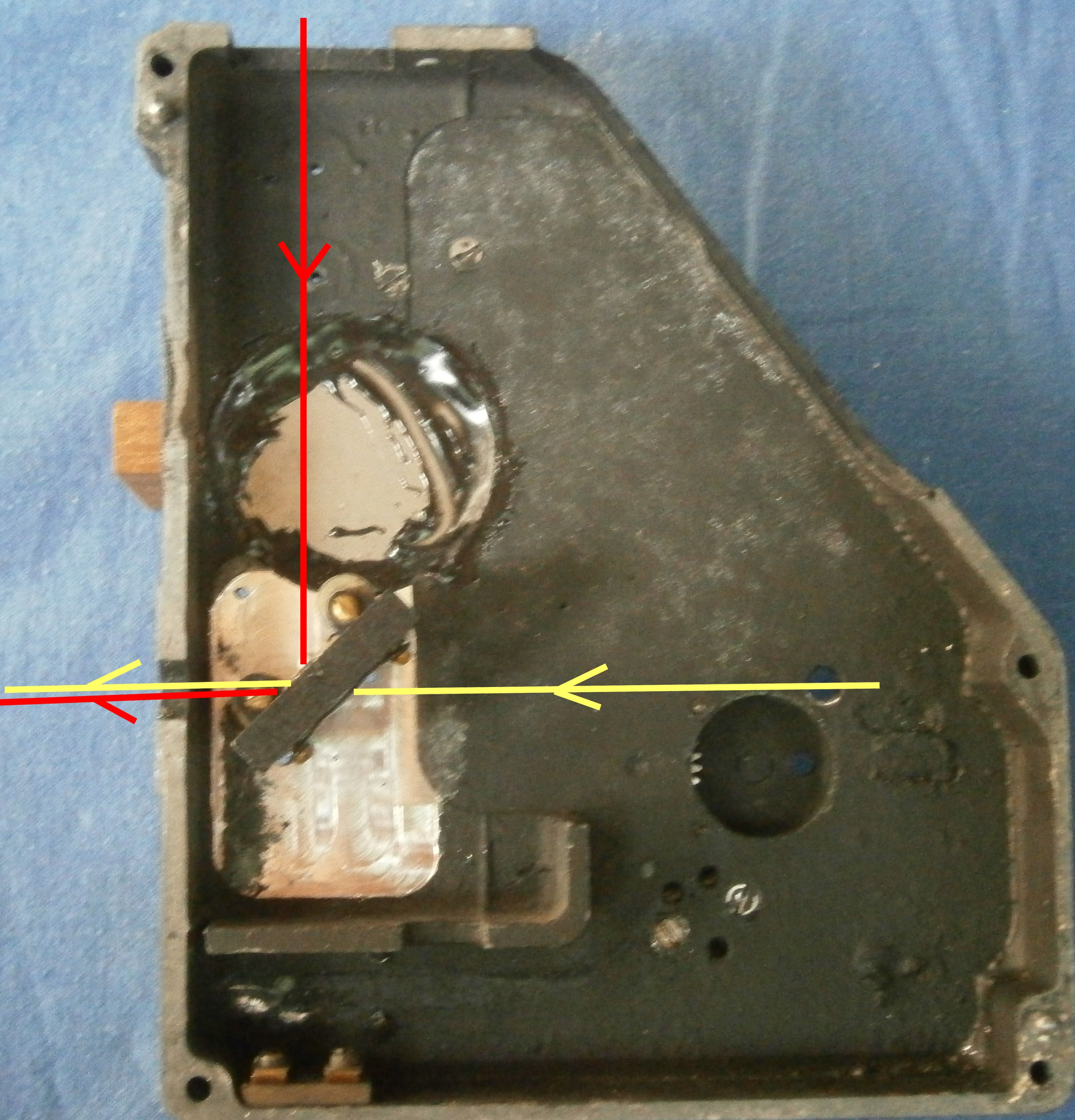
I felt that the view through the half-silvered mirror was rather restricted and also discovered that it was not well-centred on the light rays, so I replaced the mirror and its mounting with one carrying a 50% beam splitter measuring about 25 x 20 mm. This is mounted in the left half of the instrument frame, as shown in Figure 6 with the light path.. By carefully adjusting the permanent height of the mounting above the frame I was able to get the horizon view to occupy roughly half of the field of view, while the body rays occupy the whole field of view. The horizon f.o.v. is somewhat brighter, as it has passed through fewer air-glass interfaces.
For those who are not familiar with the Mark IX series of bubble sextants, the two halves mate together, located by two dowel pins and four screws a shown in Figure 7. Those interested in restoring A Mark IX, IX A or IX BM to working order as a bubble sextant will find my restoration manual a useful guide. See: My Bubble Sextant Restoration Manuals for details.


You must be logged in to post a comment.