John Pazereskism kindly sent me an e-mail, but my replies to him have bounced. If you’re reading this, John, please send me an e-mail from another address.
Of the many small-size sextants, possibly the rarest are those by Ilon Industries Inc of Port Washington, N.Y. Victor Carbonara, a prolific inventor of navigational instruments prior to and during the Second World War and one-time president of Kollsman Instruments, manufacturer of altimeters and bubble sextants, may have had something to do with its design. However, I have not been able to discover any details about Ilons. I was very pleased, then, when an Australian friend, one of the many friends I have yet to meet, entrusted me with his Ilon Mark III sextant and invited me to describe it, deconstructing it in the process if need be. The sextant is in a stout leather case with a metal zip fastener (Figure 1)

Figure 1: Case
The interior of the case is lined with red velvet, with compartments for the sextant body, an adjusting key, the handle, a sighting tube and a tiny prismatic telescope, as shown in Figure 2. A clearer view of the individual parts is given in Figure 3, which shows the parts outside the case.

Figure 2; Kit of parts in the case.

Figure 3: Parts out of case.
Figure 4 names some of the parts of the sextant for those who are not very familiar with sextant structure. The telescope is six power with an aperture of 15 mm.

Figure 4: Some of the main parts.
While it is quite usual for sextants to be stored without their telescope in place, it is very unusual for the handle to be a separate part. The sextant has a front plate which carries the telescope, the index arm with its attached micrometer mechanism, a rack with which the micrometer worm engages, the arc and the two mirrors. The front plate is attached via two pillars and a plate through which the telescope passes, to a back plate to which are attached the shades and the handle. Figure 5 gives some clues as to how the handle is attached. The upper leg of the handle has a cross pin through it and this is inserted into a slotted hole and rotated through about 30 degrees, at the same time engaging a reduced diameter of the lower leg in a plain hole in the back plate. On tightening the knurled locking nut, the handle is located and held with sufficient firmness to the back plate.

Figure 5: Sockets for handle.
Figure 6 shows the handle locked into place and also shows the means of attaching the telescope or “zero magnification” sighting tube. The ‘scope or tube screws into a dovetail slide which engages with dovetails machined in the plate that holds the rear of the the two plates together. The ‘scope can be moved transversely to admit more or less light from the horizon, depending on conditions, and then locked into place by means of a locking nut bearing on the upper gib strip. This takes the place of the conventional “rising piece”. While the human eye can just about detect a doubling in light intensity, quite small changes in intensity can improve contrast between the sky and the horizon at twilight significantly.
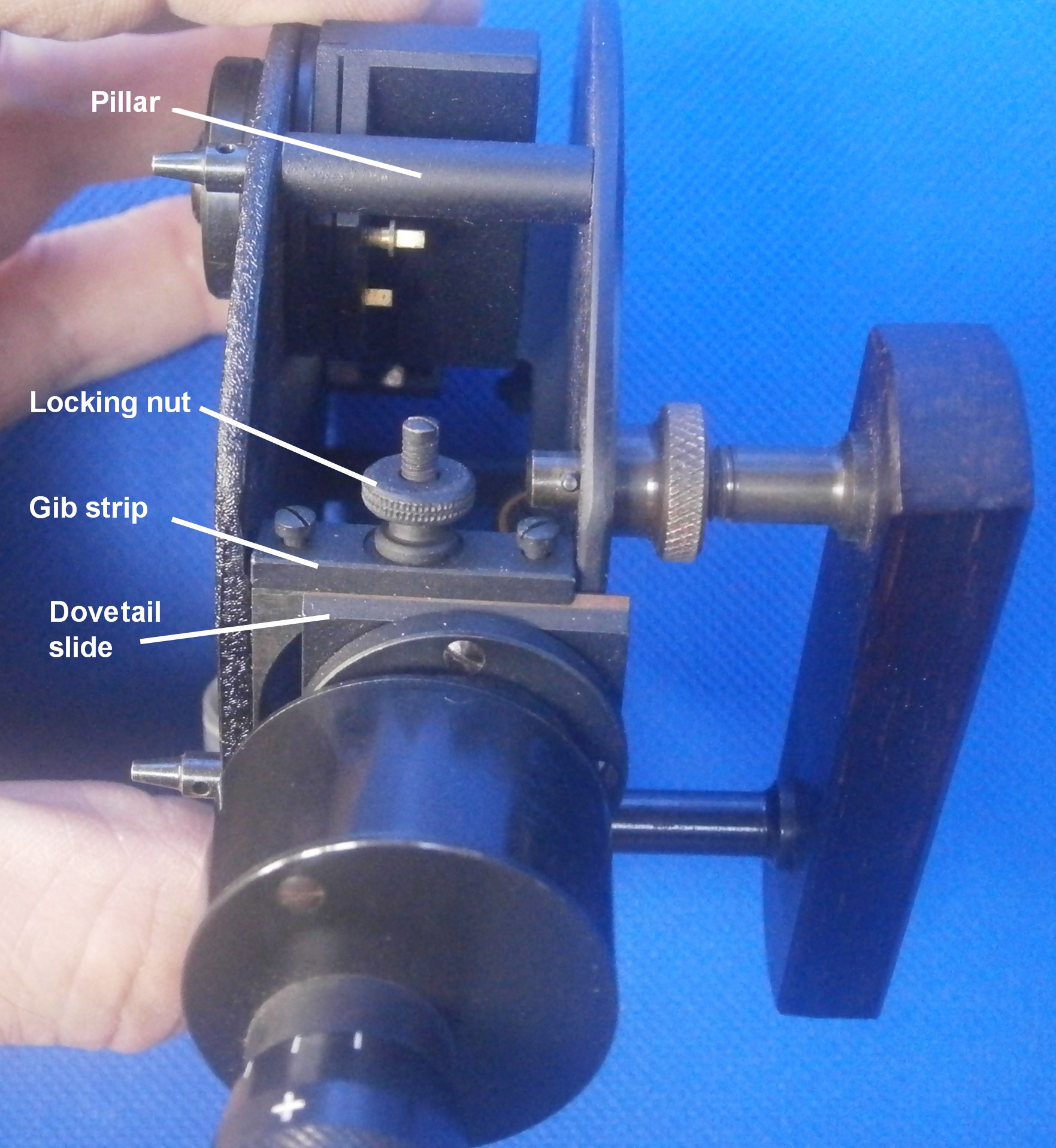
Figure 6: Handle locked into place.
Figure 7 shows how the index and horizon mirrors are tucked away safely between the plates. It also shows how up to three index shades and two horizon shades can be rotated on brackets attached to the inside of the back plate to reduce light intensity from the observed body and the horizon respectively.

Figure 7: Shades and mirrors.
The radius of the arc is a mere 60 mm (about 2.4 in.) It is traversed by an index arm outside the front plate and which rotates about a short plain bearing, the other side of which is a plate carrying the index mirror bracket. A magnifier built into the lower end of the index arm helps in reading the whole number of degrees (Figure 8).

Figure 8: Micrometer index.
A rack is machined into the rear of the front plate and is engaged with the worm of the micrometer mechanism (Figure 9). An 18 mm diameter micrometer drum allows single minutes to be read off with ease. The mechanism follows the practice of Heath an Co in swinging the worm out of the plane of the rack by means of a spring loaded release catch, so that the index arm can then be moved rapidly.. The swing arm that carries the worm in its bearings rotates between cone-ended screws that can be locked in place when all backlash has been removed.

Figure 9: Micrometer mechanism.
Axial play of the worm shaft is removed by an adjustable bush that is also locked into place when it is judged that there is no axial play of the worm in its bearings (Figure 10). A tongue (best seen in Figure 9) forming part of the rear swing arm trunnion bearing projects to form a keeper that prevents the index arm lifting off the front plate.

Figure 10: Detail of micrometer mechanism.
Figure 11 shows the light path, in red from a heavenly body at about 60 degrees altitude and in yellow from the horizon. Both mirrors have their reflective surface on the front and presumably this was chosen so that they could be cemented firmly into their brackets without the need for clips, which, at this scale would be extremely small and fiddly to fit. The horizon mirror has no clear-glass portion and the light from the horizon simply passes over the top of the mirror to combine with the rays from the observed body. In some respects, this is a disadvantage as the clear portion of the more usual horizon mirror reflects about 10 percent of the light coming to it from the heavenly body and increases the overlap in the view of the body and the horizon.

Figure 11: Light path.
Figure 11 shows some of the structure of the horizon mirror bracket. Horizontal and vertical slots almost meet, leaving a slightly flexible diaphragm of metal between, so that the mirror can be adjusted in the vertical plane by two screws, the nearer one of which in the photo, as it were, pushes, while the other pulls. The two are adjusted against each other to correct side error. This is seen in a different view in Figure 13. The index mirror bracket is slotted in a similar way to allow adjustment for perpendicularity in the usual way.

Figure 12: Detail of horizon mirror bracket.
To adjust for index error, the whole bracket rotates about a screw through the plate and two adjusting screws bear against each other on the opposite sides of a post. When adjustment is complete, the screw through the plate is locked.
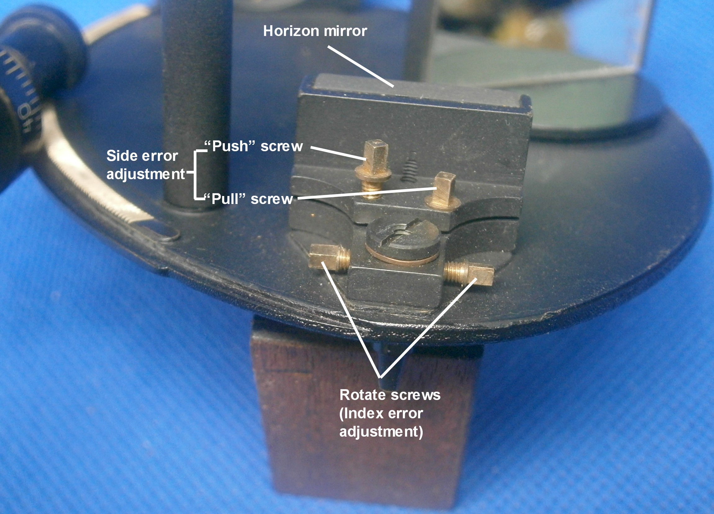
Figure 13: Horizon mirror adjustment.
It is not clear for whom this interesting little sextant was intended. Produced in small numbers, it must have rivaled a full-sized sextant for cost. There are plenty of box sextants around, but the Ilon is much easier to read than the crowded vernier scale of a box sextant and though the latter were useful to surveyors for reconnaissance surveys and to artillerymen for setting up their guns, improvements in survey instruments may well have made the sextant redundant for these purposes. The professional seaman is unlikely to have wished to be seen with anything other than a full-sized instrument, leaving only the well-heeled yachtsman or the collector as a possible purchaser. Perhaps this ingenious little instrument was too good for its own good, as they appear to be excessively rare, suggesting perhaps that it did not sell well.
I am grateful to Murray Peake for the loan of his instrument.
3 October 2014: In response to this post, Alan Heldman remarks that the design “…would easily lend itself to giving the user the option of putting the handle on the left side as well as the right side. With the handle on the left-hand side, the user could easily work the micrometer screw with his right hand.” There does not seem any reason why the handle could not be retrofitted to the left plate, though it would have to be almost horizontal and high up to clear the index arm.
Chris White writes “ Just saw the Ilon sextant article. Victor Carbonara was my grandfather and i worked at Ilon for a couple years in the 1970’s. I actually assembled and sold a number of these sextants from the parts inventory years after they had been discontinued.
It is a great sextant for marine use. Fussy to build due to the short arm requiring higher accuracy. “

You must be logged in to post a comment.