This post is preceded by one on “The Observator Mark 4 Sextant”.
I was recently asked if I would restore a sextant which had been given to Laura Dekker prior to her setting out from the Netherlands in August, 2010 to circumnavigate the world in a yacht. She had finally come to rest where she had been born, on her parents’ yacht, in the New Zealand city of Whangarei, some 200 km south east of my home in Pukenui. It was my pleasure to undertake the task and later to return the instrument to this remarkable young person. She describes her battles with the Dutch authorities, who refused to allow her to set out at the age of 14 years, and her subsequent voyaging in her book: One Girl, One Dream (Harper Collins, 2014).
I had previously described the interesting Observator Mark IV sextant (April 2014). Laura’s instrument was plainly of an earlier era, probably from the 1950’s. Figure 1 shows the sextant as received. It bears no particular inscription, so I have chosen to call it the “Observator Classic”. The frame is of bronze and the whole sextant is exceptionally heavy at 2.32 kg (5 lbs 2 oz), compared to a Hughes and Son three ring micrometer sextant at about 1.5 kg and a W Ludolph sextant of similar robust build at 2.05 kg. It has a lighting system and as Figure 1 shows, corrosion had caused the lighting fixture to part company with its stem (All figures may be enlarged by clicking on them. Return to the text by using the back arrow.).

Figure 1: Sextant as received.
Figure 2 shows the condition of the rack and the entry to the battery compartment, complete with long-dead batteries. One can also see the exceptionally heavy ribbing of the frame, suggesting that it was perhaps a sand casting. Patient wire brushing restored the battery compartment to a conducting state while, once the stem of the lighting fixture had been persuaded away from the index arm fitting, it was the work of a few minutes to silver solder the stem back into place.
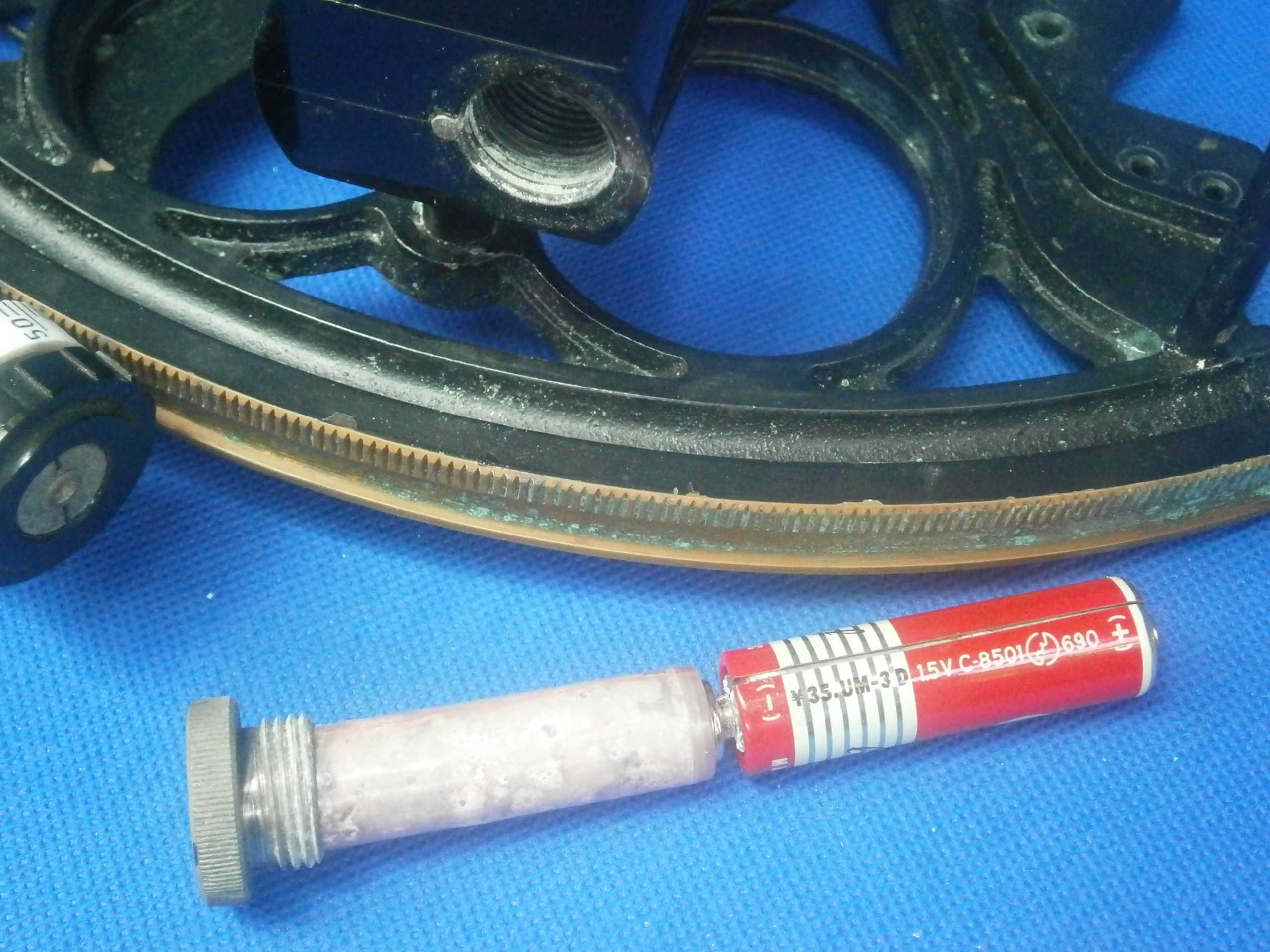
Figure 2: Rack and battery compartment.
Figure 3 shows the structure of the micrometer worm and its shaft, perhaps somewhat over-engineered, but robust and adequate to purpose. The shaft has a taper on to which the worm is forced by a nut to ensure concentricity of the worm. At the other end of the shaft , a combined thimble and drum screws on to the shaft. It is located by a parallel register ahead of the threaded portion and secured in place by a locknut. The shaft rotates in two bearings in a bronze swing arm and axial preload is provided by a spring which is held in place by a cap that screws into the swing arm.

Figure 3: Micrometer exploded.
Figure 4 shows more detail of the micrometer mechanism. The cone ends of two screws, one each side of the swing arm engage with conical holes at each end of the arm and these screws are adjusted so that there is no end play but the arm can rock freely between the two screws, which are then locked. A leaf spring (not seen) between the swing arm and the lower end of the index arm holds the worm in engagement with the rack and the worm can be disengaged by squeezing the two together. Extensions of the trunions that house the cone-ended screws act as keepers to prevent the lower end of the index arm from lifting off the frame and keep the worm aligned with the rack.

Figure 4: Detail of micrometer mechanism.
The telescope rising piece design lies somewhere between the more-or-less elaborate nineteenth and early twentieth century arrangements for adjusting the height of the telescope above the frame (see, e.g. https://sextantbook.com/?s=fine+C+Plath), and the very simple later vee and flat used by most makers after about 1950. The telescope rising piece is square and fits closely into a socket screwed to the frame. A thumb screw locks it into position (Figure 5).
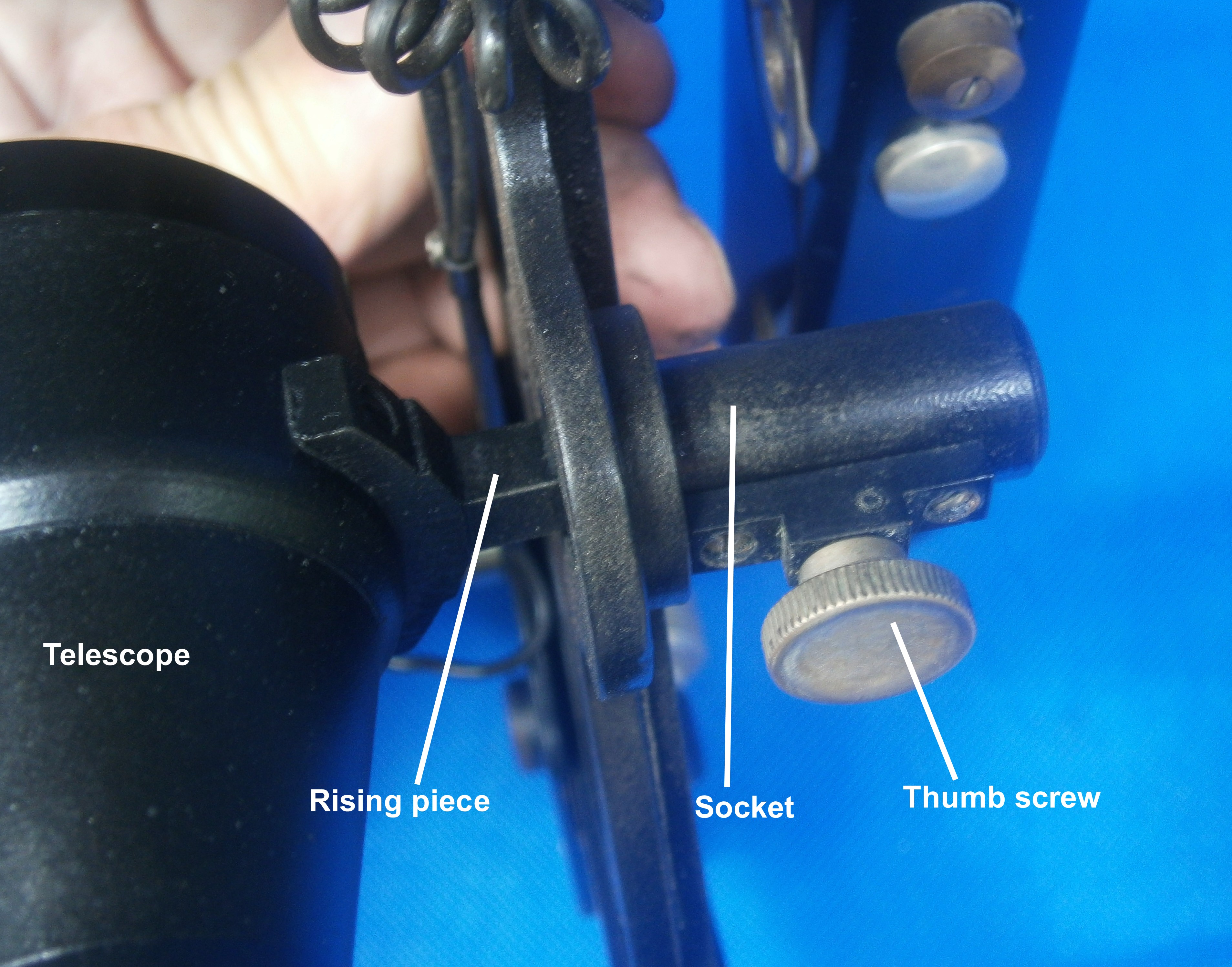
Figure 5: Telescope mounting.
After cleaning up, making and replacing the mirrors, it remained only to repaint the instrument to give the pleasing result shown in Figure 6 and to clean up and re-varnish the case (Figure 7).

Figure 6: Finished instrument.

Figure 7: Restoration complete.

You must be logged in to post a comment.