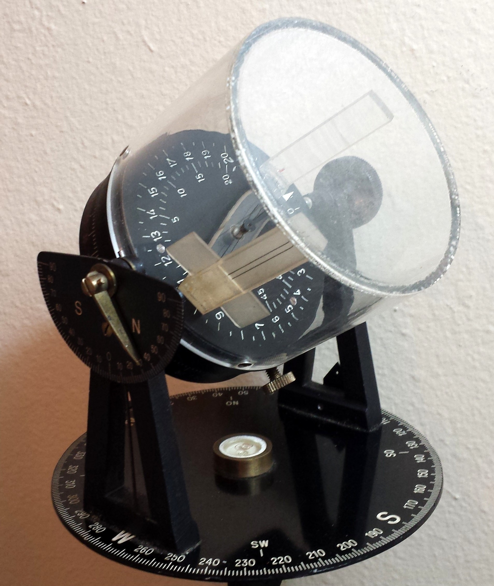
Frontispiece: Dan LaPorte’s sun compass.
This post was preceded by “A Fleuriais’ Marine Distance Meter” A Stuart Distance Meter”;“A Russian Naval Dip Meter”; and “An Improvised Dip Meter”
Sometimes, kind people lend me their precious instruments for me to deconstruct and examine so I can post details on this site. I invited Dan LaPorte to contribute a “guest blog post” and he has kindly obliged. Dan’s contribution is in blue, and my comments and additions are in black.
Last year I obtained a WWII Plath sun compass via an e-bay purchase. At the time I really didn’t know exactly what I had bid on and won, but I did know it was something out of the ordinary.
First, a little about me and why I would be remotely interested in such an item. I am a retired US Merchant Mariner having sailed for some thirty-five years at sea, twenty of those as a Ship’s Master. During that time, I acquired many skills and interests, one of them being magnetic compass correction. For years I’ve used an Abrams and an Astro sun compass for such duties. Both work on the same basic principal of local time or hour angle to obtain a true bearing of the sun or other celestial body. Hence I was immediately interested in the Plath sun compass.
Upon delivery of the item I was saddened to find that the clock work no longer functioned (the Plath uses a Junghans 30 clock work with optical sight for taking a bearing of the sun). In fact the Junghans 30 movement was also used in the ME 109 fighter of the same era. The idea is to set the correct time (more on this later), so the sun compass will track the sun’s path and hence a constant bearing using the sun can be obtained. When functioning and set correctly a true bearing can be recorded of a landmark to obtain a position, or drive (or fly) from a known position to another by following the desired course. Another use of the Plath would be to check and correct an aircraft’s magnetic compass while on the ground.
After a bit of research I found that this model was used almost exclusively by German troops deployed to the North Africa corps during WWII. Of course all this would have been unknown to me if not for the assistance of Mr Malcolm Barnfield. By contacting Malcolm via his web site: http://www.sundials.co.za , I was able to obtain a wealth of information on the Plath. Malcolm is without a doubt one of the most knowledgeable people in the world on the topic of sundials, sun compasses and their use. Without Malcolm’s expertise on the topic I would have certainly been lost for much longer, and perhaps forever. Malcolm was also good enough to put me in contact with other very talented men, highly regarded on the same topic, such as Mr Konrad Knirim who provided a manual for the Plath, and Mr Kuno Gross, who translated it from German to English for me. These highly accomplished men in their fields were good enough to assist me in my search for information regarding the Plath.
While history of the Plath was very interesting, it did nothing to solve the one large remaining problem – it simply didn’t keep time and thus was nothing more than an interesting item to marvel at and only ponder at its use.
Enter Bill Morris. Bill and I had communicated for months on various topics related to celestial navigation both air and sea. Bill is regarded by all that know him as one of the most knowledgeable people in the world where navigation instruments and their structure are concerned. Bill has written books on the topic and provides detailed manuals for repair of several sextant types both aeronautical and nautical. His manuals are truly works of art and allow the layman to repair and bring sextants back to working order. Bill had in the past repaired an old A10A aircraft sextant for me that works perfectly to this day. Given his talent for repairs, knowledge of machine tools and ability to work on intricate and complex antiques with a sure touch, I asked if he would be good enough to have a look at the workings of the Plath. I should state at this point that I was, and remain very protective of the Plath and would not allow just anyone to begin repairs on it. Bill was my first and only choice that I would trust enough to allow any attempt at repairs. As luck would have it Bill was to travel to Katy in Texas, not all that far from my home. Add to this I would be able to finally meet Bill face to face. In short it was a perfect and fortunate turn of events.
I was able to meet Bill and his lovely wife for a visit in August of this year. We enjoyed a very nice chat and lunch, covering topics ranging from navigation to what should be seen while in Texas. I left the Plath safely in Bill’s hands, with hopes he could repair it. A mere week later I had the Plath in my hands and working perfectly.
At this point the Plath was repaired, and I had a basic knowledge of how to use it. When the Plath arrived I at once set it to local standard time adjusted with the EQT ( Equation of time) from the nautical almanac. To my dismay it did not point to North or any other direction. In fact is seemed to be some 15 degrees off to the East at best. That is, I would have to be another time zone to the East for the Plath to be anywhere near correct in obtaining a true bearing. Adding to my frustration, I was not entirely clear on how to orientate it to obtain a true bearing (the manual giving scant information in the translation). I set both the Abrams and Astro Compass in a hope to clarify the situation, this only proved to entangle my thoughts even more, at least for the moment.
A few words about the equation of time are perhaps appropriate. Our daily life is governed mainly by the sun and its passage across the sky is not perfectly regular. It slows at some times of the year and speeds up at other. This is partly because the Earth’s orbit is slightly elliptical, so that it speeds up when nearer the sun and partly because the Earth’s axis of rotation is inclined at about 23 1/2 degrees to the plane of its orbit, so that the component of the Sun’s apparent velocity parallel to the equator varies with the seasons. It is very difficult to make clocks to follow these variations, so the concept of mean solar time was invented, the average time for the Sun’s apparent rotation around the Earth. The difference between the apparent time on a given day and the mean solar time is known as the equation of time, often shown as a graph as in Figure 2, and in the bottom right hand corner of the daily pages of the Nautical Almanac. In the sun compass, it has to be applied as a correction on a given date to the mean time so that the alidade will point correctly to the sun.
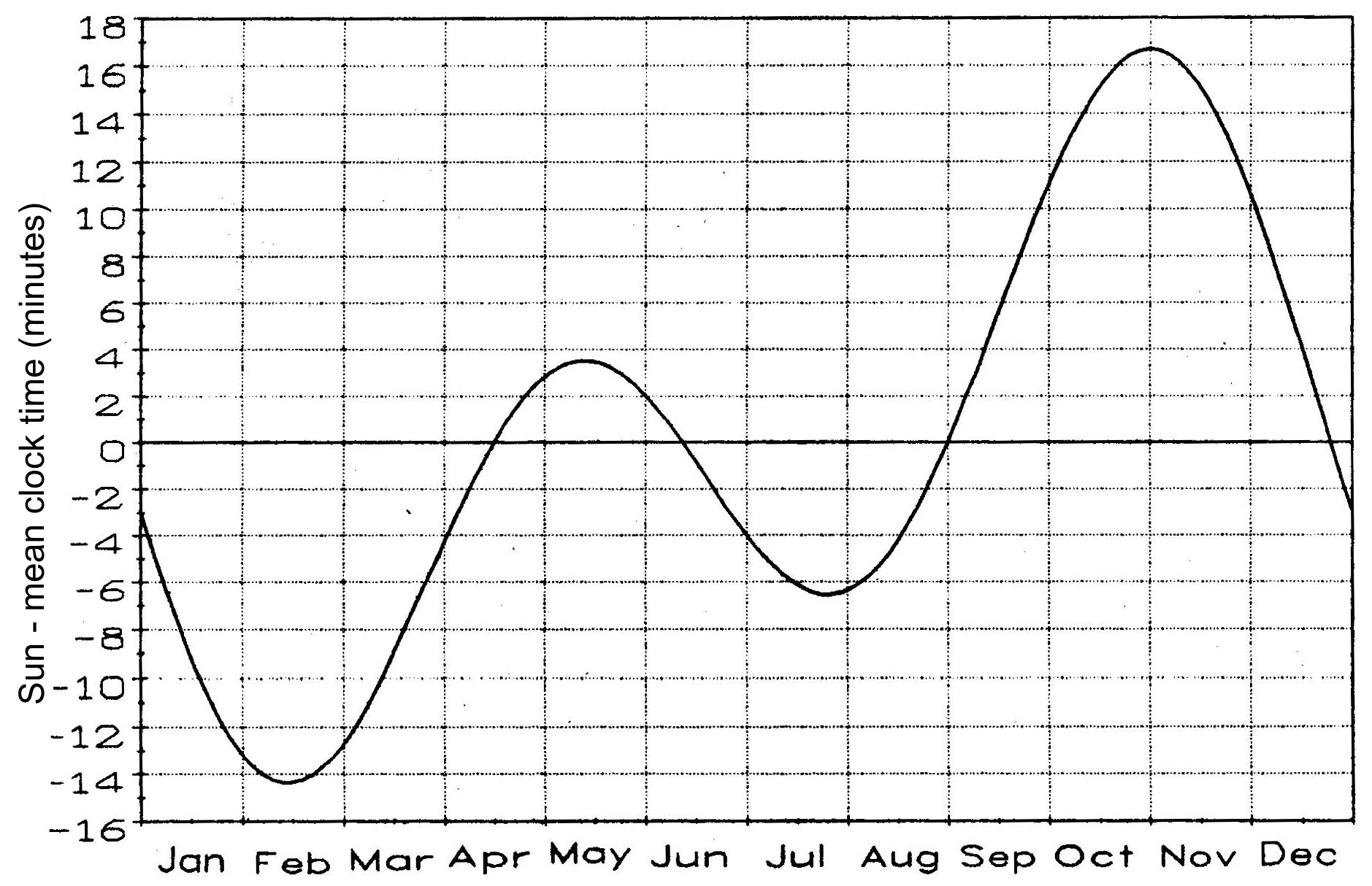
Figure 2: The equation of time.
After further study I found the problem. To outline what the problems was I first have to explain the use of the two sun compass types I was more familiar with. As stated previously, my tools used for obtaining a bearing of the sun or other celestial body was the Abrams or Astro Compass. The Abrams uses local standard time, adjusted east or west of the standard time meridian, the observer’s approximate latitude and an adjustment for EQT provided on the face of the sun compass. When all these details are known and set the instrument will provide the desired bearing by using the shadow of the sun. The instrument has to be updated by moving the time marker one mark on the scale every four minutes. This of course is due to the movement of the sun covering one degree of longitude every four minutes. Simple when you know how. The Astro Compass uses the settings of: Local Hour Angle (LHA), declination of the body and latitude of the observer. The declination of the body is obtained from the Nautical Almanac, LHA is calculated from your known longitude and applying it to the GHA of the sun or other celestial body. Latitude of the observer would also need to be known and set on the instrument. As with the Abrams the Astro needs to be constantly updated by moving the LHA scale in keeping with the sun’s motion across the sky.
Why am I boring the reader with these details? Simply to drive home the use of the Plath and the ingenious setting of the unit. Unlike the Abrams and Astro the Plath is set to GMT standard time (not DST). The user would also need to apply EQT to the time setting in order to obtain solar time with the EQT sign ( -/+) reversed due to the correction from a local time to GMT. Once set to GMT – Solar time (GMT with EQT applied) the user then simply sets his latitude and longitude on the Plath. No further corrections and no almanac entries are needed. As long as the Plath keeps correct time, and the user updates the estimated position of latitude and longitude, the unit will continue to function. My mistake was in setting the Plath to local time. I had wrongly assumed local time would be used as with my other instruments. The Plath’s use of GMT is a perfect solution when one has time to reflect on the subject.
Needless to say when the details of correctly setting the Plath were known and understood another test was in order. So, one afternoon with the sun high and bright in the sky I set the Plath. It should be noted that as with all other sun compasses it needs to be mounted securely to a stable platform and levelled with the provided spirit level. I also set the Abrams and Astro compass at the same time, a kind of a sun compass smorgasbord if you will. To my amazement the Plath indicated true north as checked by my Abrams and Astro Compass (any course could have been selected for the test). Given that the ultimate test of the Plath was to maintain a true bearing for hours or even throughout the night a test for the rest of the evening continued. I allowed the Plath to run for a few hours checking it now and then. As per the design, the Plath displayed a constant true bearing until sunset due to the clock works keeping time and following the transit of the sun across the sky. The Abrams and Astro compass would have had to be manually corrected continually for the entire event. The value of the Plath became even more clear when you imagine using it in a desert with no natural land marks. Given the successful test I personally would not have a problem using it for land navigation across a desert to this day if I knew what course I needed to travel from my location to destination. No need for GPS signals or the like. Just simple old style navigation would serve the user very well indeed. In fact I’d prefer to use the Plath instead of the Abrams or Astro compass due to the Plath’s ability to constantly maintain the required bearing, thanks of course to the Junghans clock works.
The final test was the following morning. As the sun rose in the East the Plath tracked perfectly still displaying the true bearing of North as she was set the evening before. Perfect! After seventy plus years the Plath with the assistance of Bill Morris worked as she worked many years ago in the North African desert.
I wish to thank Dr Bill Morris, Mr Malcolm Barnfield, Mr Kuno Gross, and Mr Konrad Knirim with having similar interest, assisting me, answering my questions, being patient, and at times commiserating with me on this project. These men: doctor, military historian, engineers, authors, experts in their fields, took the time to assist a retired sea Captain with his quest to restore an antique sun compass to operational status. Simply put, without them and their assistance the Plath would have remained locked away in my study with other odd instruments, not used, not understood and in a non-functional condition. It would have been an unfortunate end for such a fine instrument. As it turns out she may well run another seventy plus years.
Captain Dan LaPorte (ret)
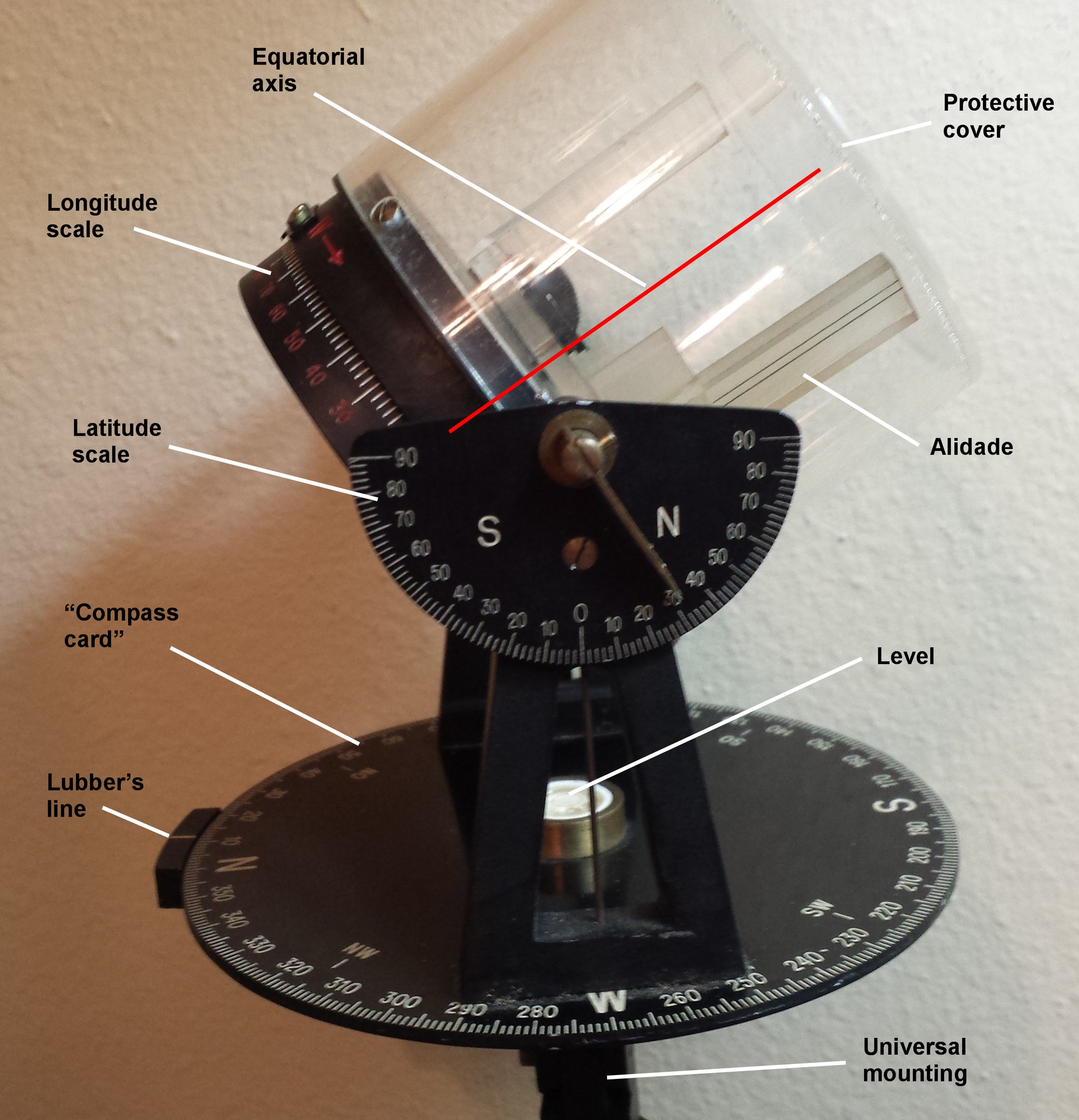
Figure 3: General arrangement.
Now for a few anatomical details. The compass is mounted on the vehicle or aircraft via a universal joint, which can be quickly locked or unlocked in order to level the base plate (which I have labelled “compass card” in Figure 3 above) using a circular level in the centre of the plate. The base plate index corresponds to the lubber’s line in a magnetic compass and the line can be correctly aligned with the fore and aft axis of the vehicle using a sort of iron sight. In Figure 3 this can be seen as a thin vertical rod in a gap in the trunnion above the W of the base plate. On the other side is a point, just visible in Figure 1. The two trunnions support the horizontal axis of the compass and this axis is provided with a latitude scale on one end and a knurled locking knob on the other. A moment’s thought shows that when the scale is set to the local latitude, the equatorial axis, which I have drawn as a red line, will be parallel to the Earth’s axis. The horizontal axis bears a clock with a twenty-four hour dial and the clock can be rotated inside an equatorial mounting ring provided with a longitude scale and locked at the local longitude.
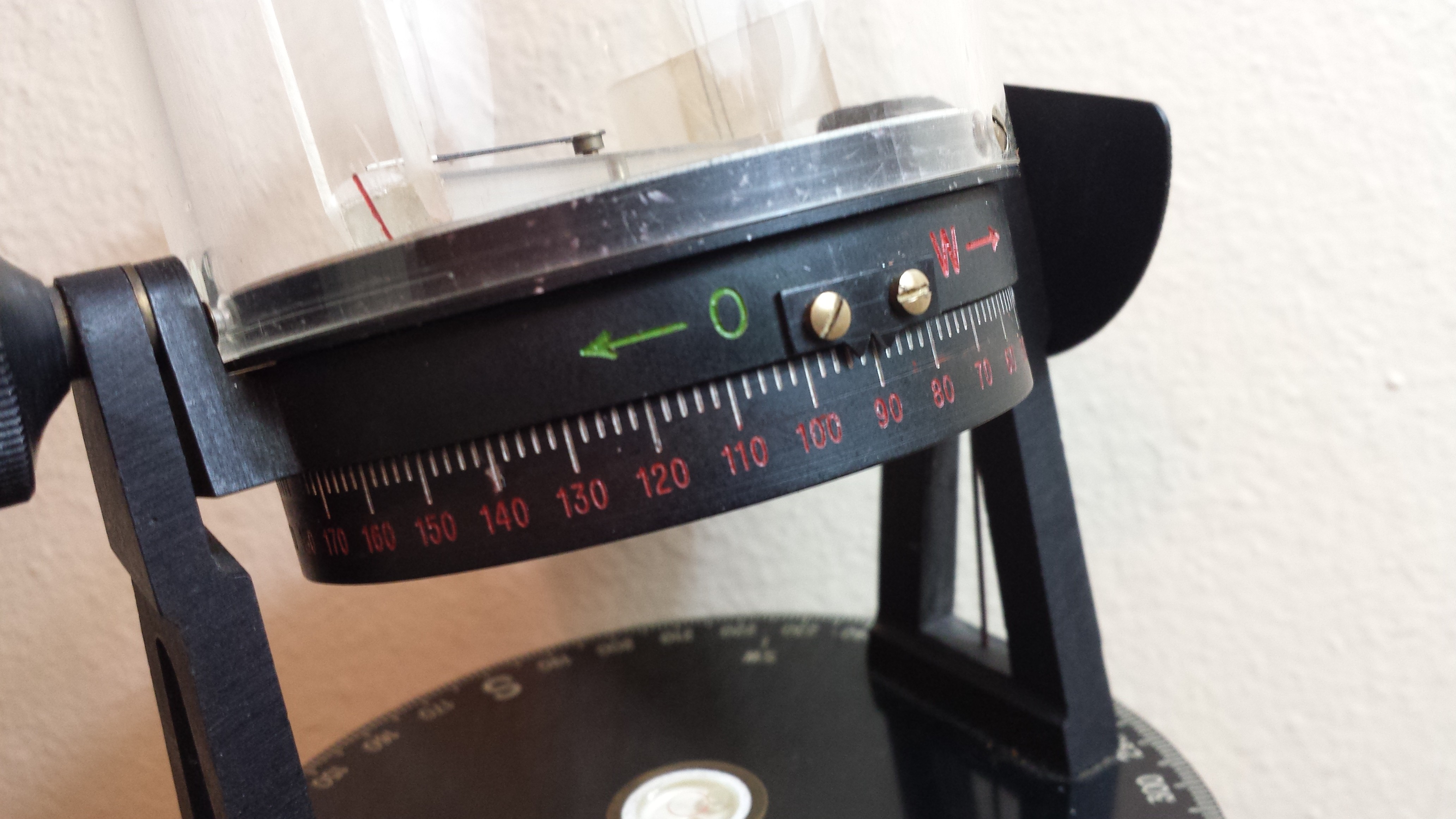
Figure 4: Equatorial mounting ring and longitude scale.
The watch is provided with a rather unusual hour hand in the form of an alidade (Figure 5a) and also has a conventional minute hand.

Figure 5a: Structure of the alidade.
The alidade is made of Perspex (Lucite). One end has a vertical cylindrical lens that projects an elongated image of the sun on to a ground screen at the other end. The screen has two vertical setting lines and a lower, transverse extension to help in initial setting. When the time is set to the correct Universal or Greenwich Mean time, adjusted for the equation of time, and the latitude and longitude scales set to their local values the base plate is rotated so as to bring the elongated image of the sun between the setting lines. If the vehicle is pointing north, the base plate index will then indicate north. If the vehicle turns and the base plate re-adjusted to bring the sun back between the setting lines, the direction of travel will be indicated by the base plate reading. The clock will keep the alidade tracking the sun correctly as long as the direction of travel does not change and if the direction of travel does change it is necessary only to bring the alidade back into alignment to get a correct indication of the new direction of travel. Amateur astronomers will recognise this as an adaptation of the familiar equatorial telescope mounting. The whole is enclosed by a protective Perspex cover. Figure 5b gives another view
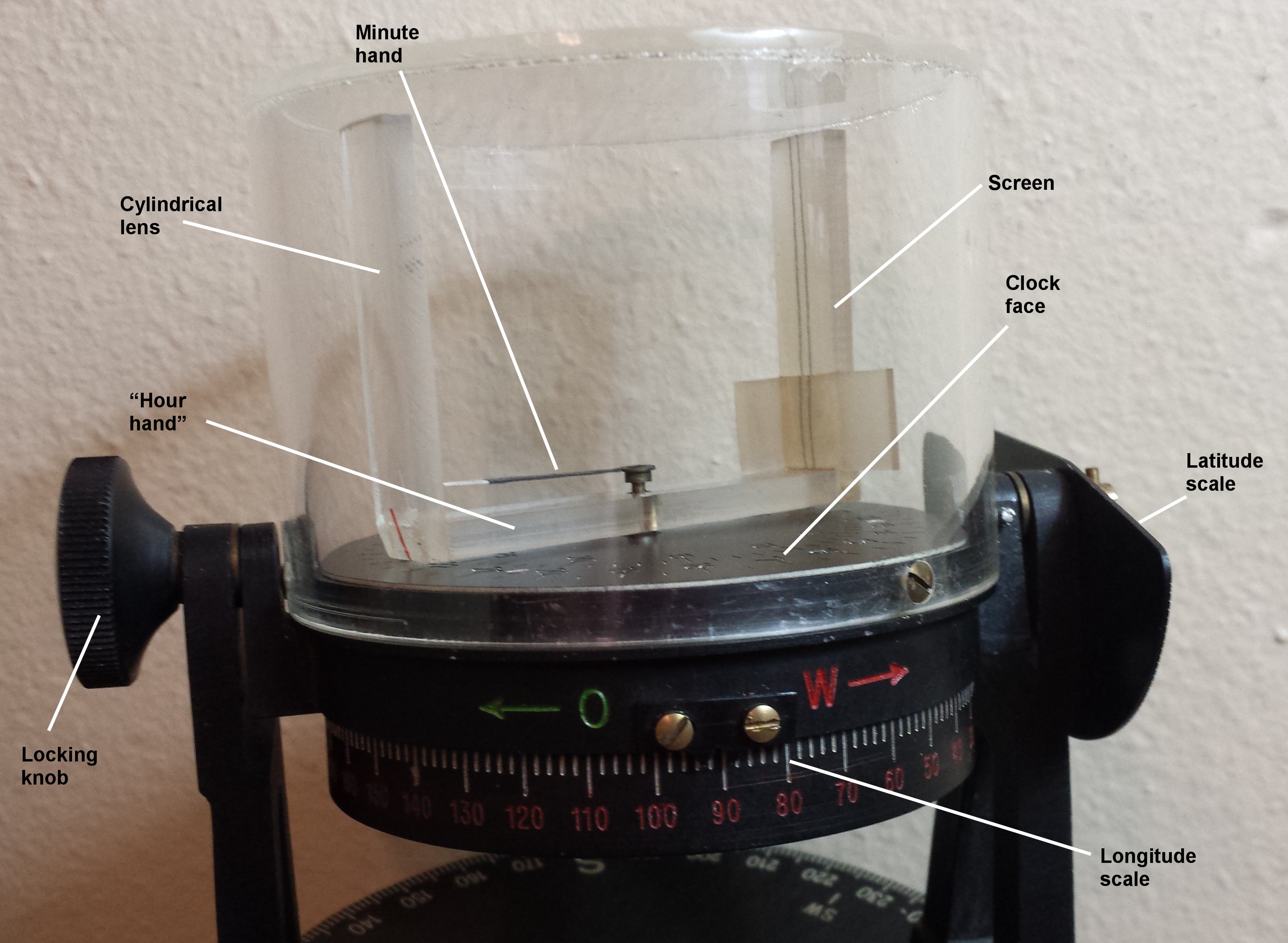
Figure 5b: Further view of alidade and scales.
I do not propose to give many details of the clock mechanism except to point out that, somewhat unusually, it is wound up by rotating the spring barrel rather than by rotating the spring arbor. This allows some simplification of the internal power train and also allows setting of the hands by means of a co-axial arbor (Figure 6).
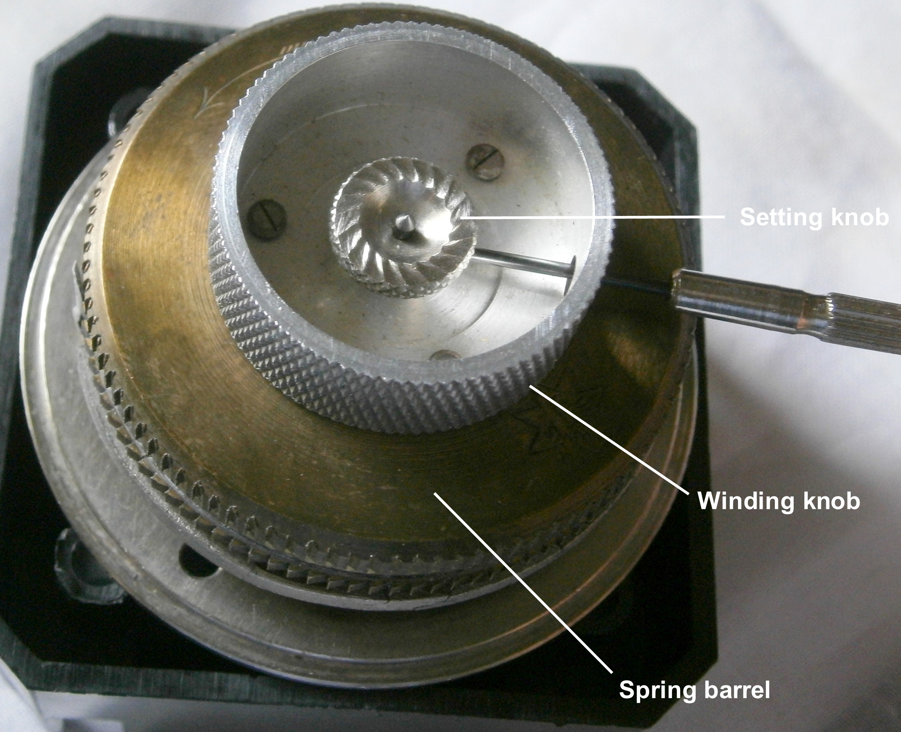
Figure 6: Winding and setting knobs.
Figure 7 shows how power is transmitted to the train from the spring via the central winding gear.

Figure 7: Winding gear detail.
Dan and I would be glad to know of any errors or significant omissions and to hear from other owners about their experience with this ingenious instrument.
Bill Morris
Pukenui
New Zealand


You must be logged in to post a comment.