A French sextant restoration

25 07 2022

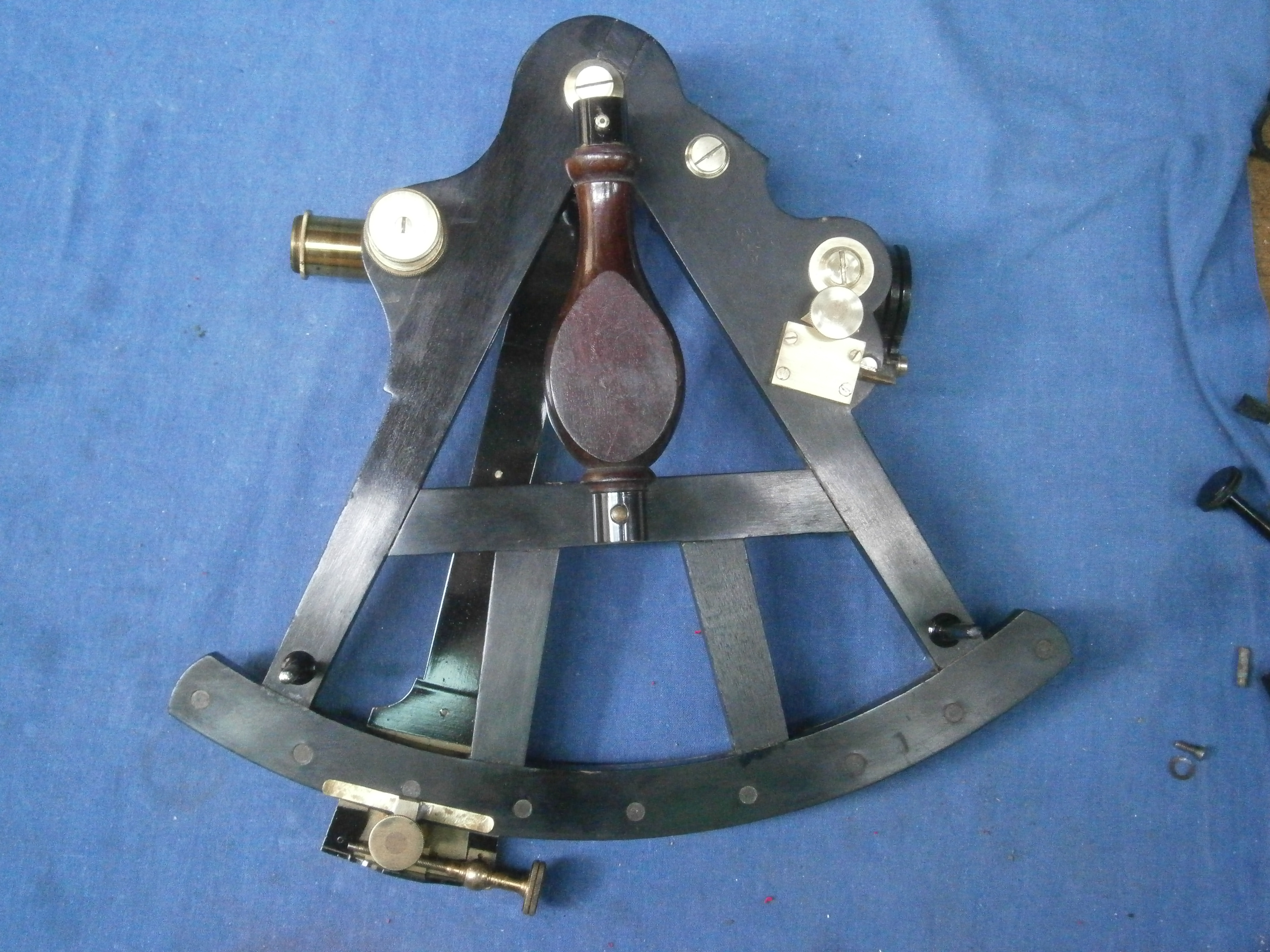
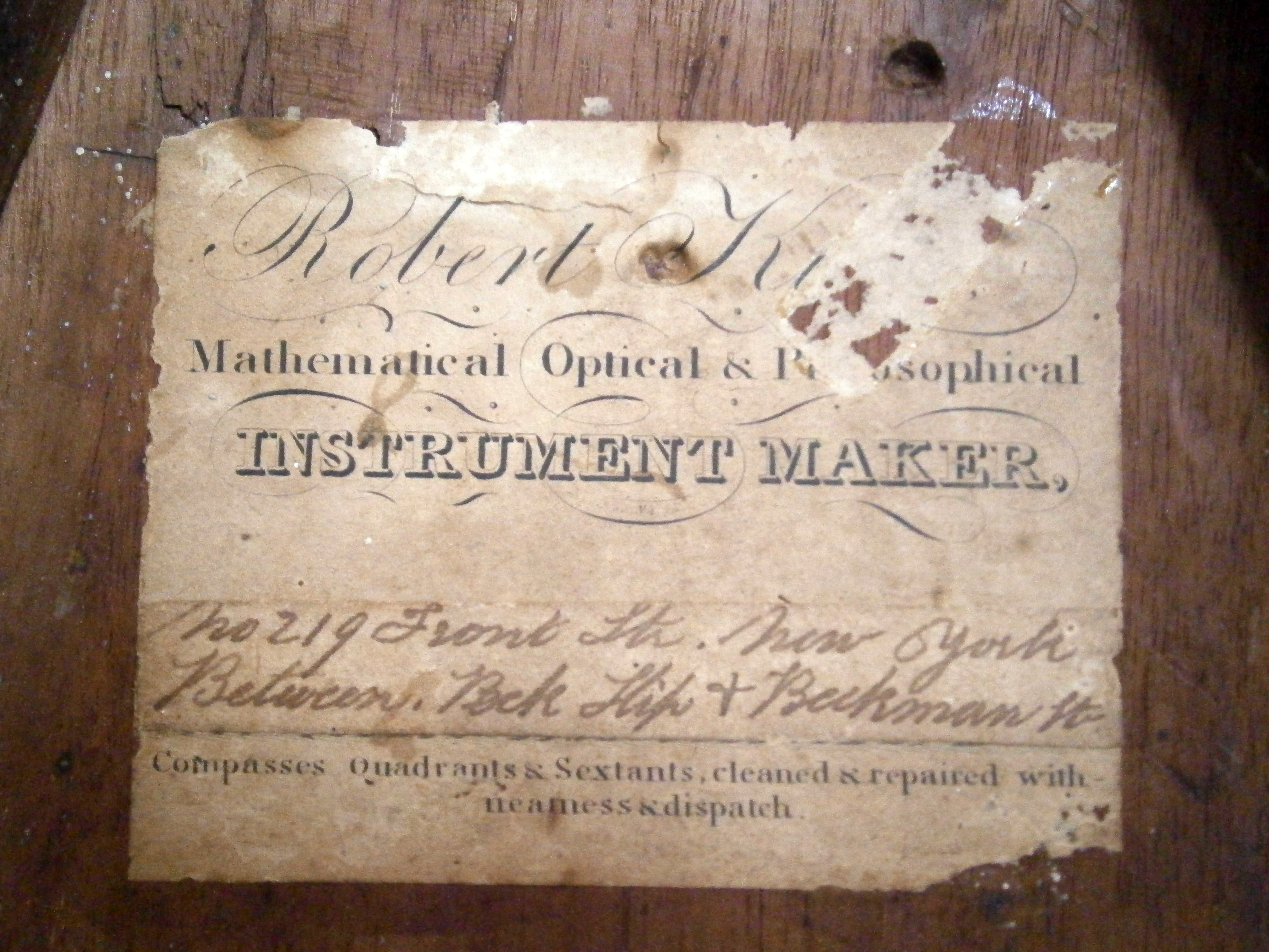
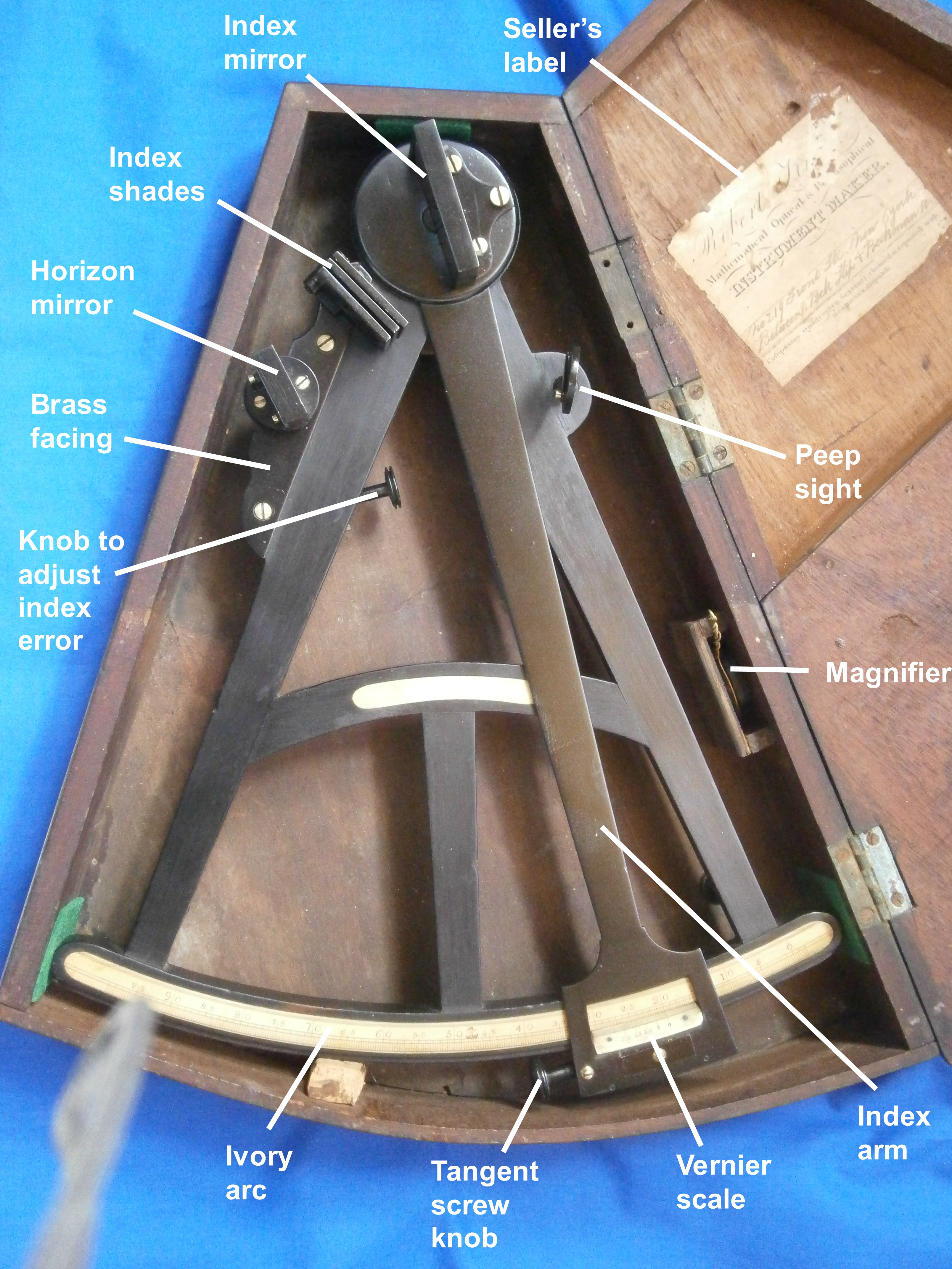
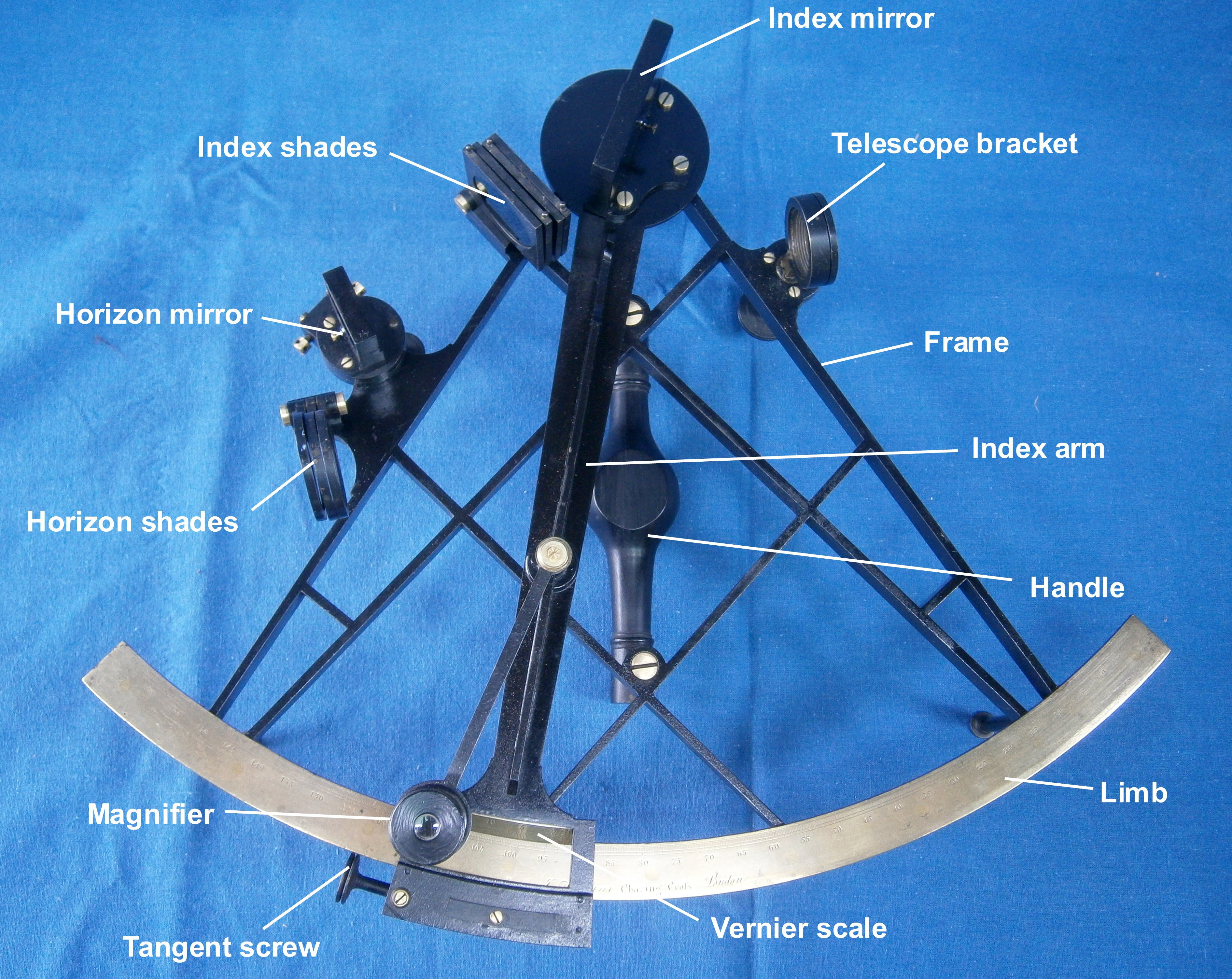
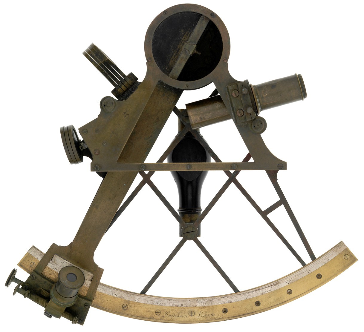
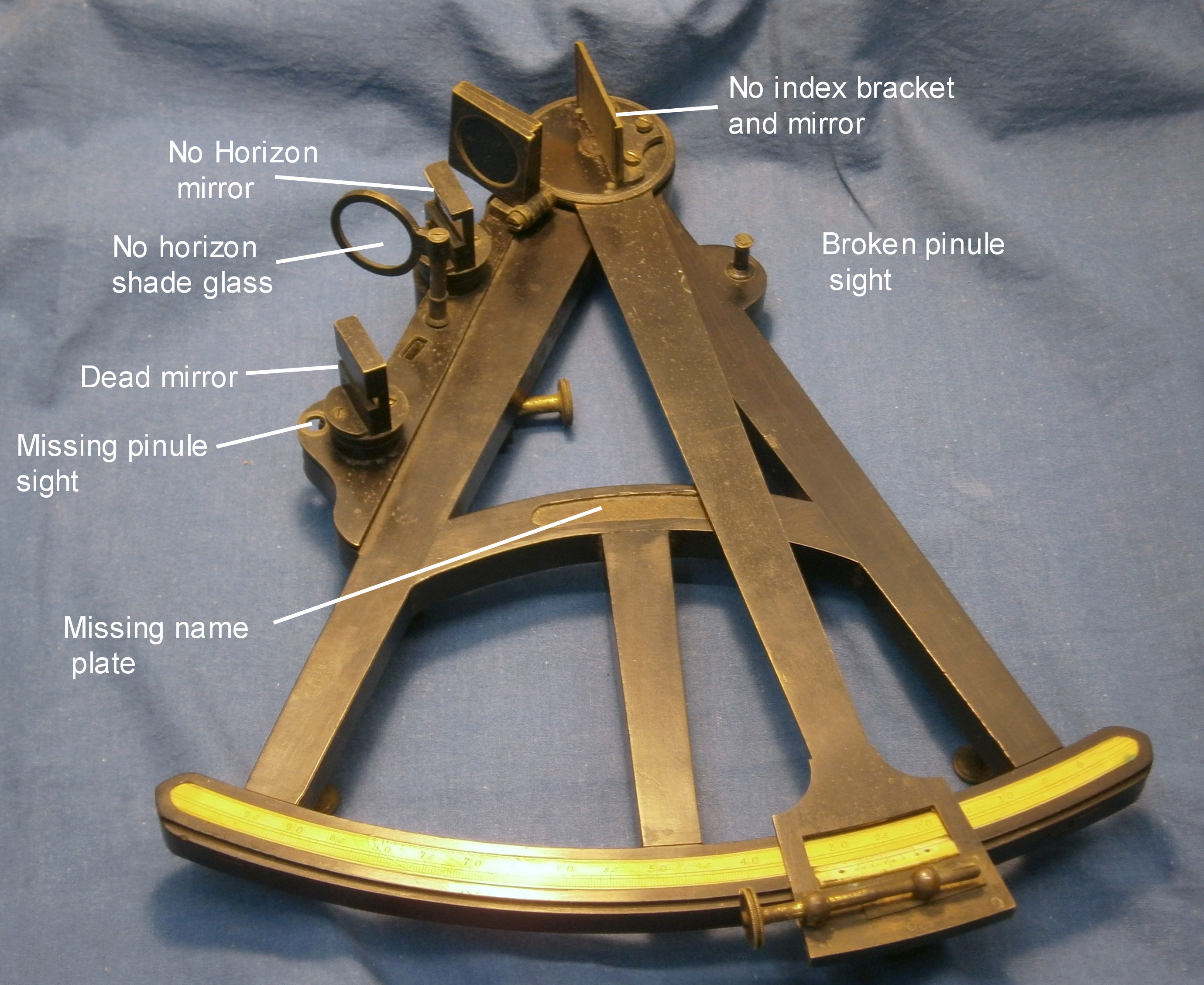
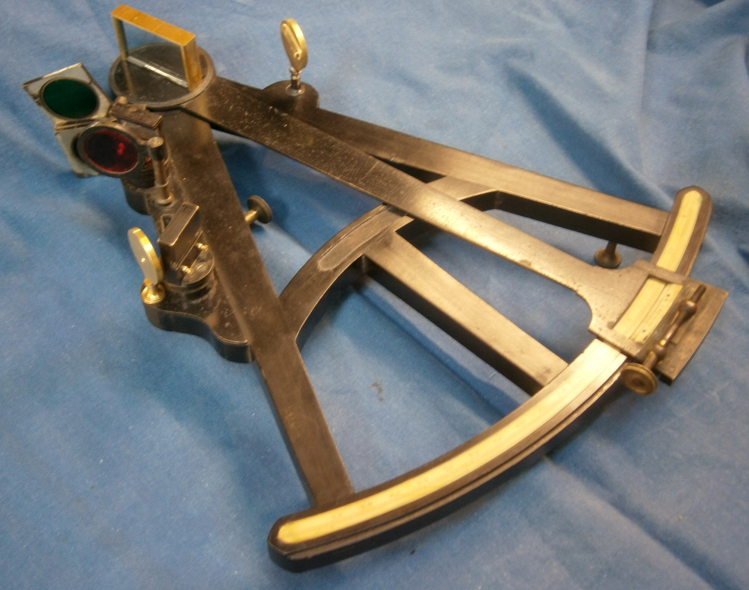
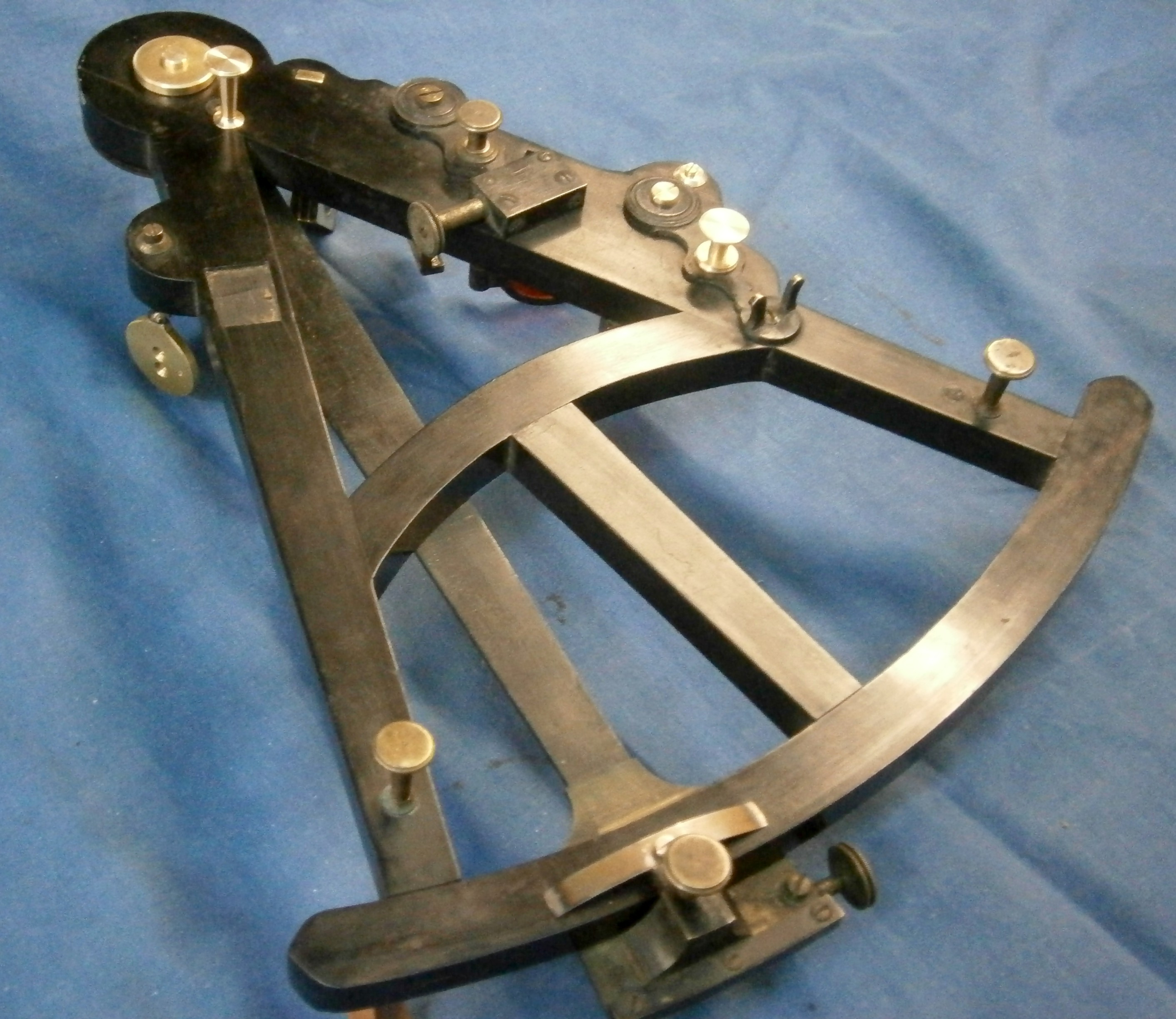
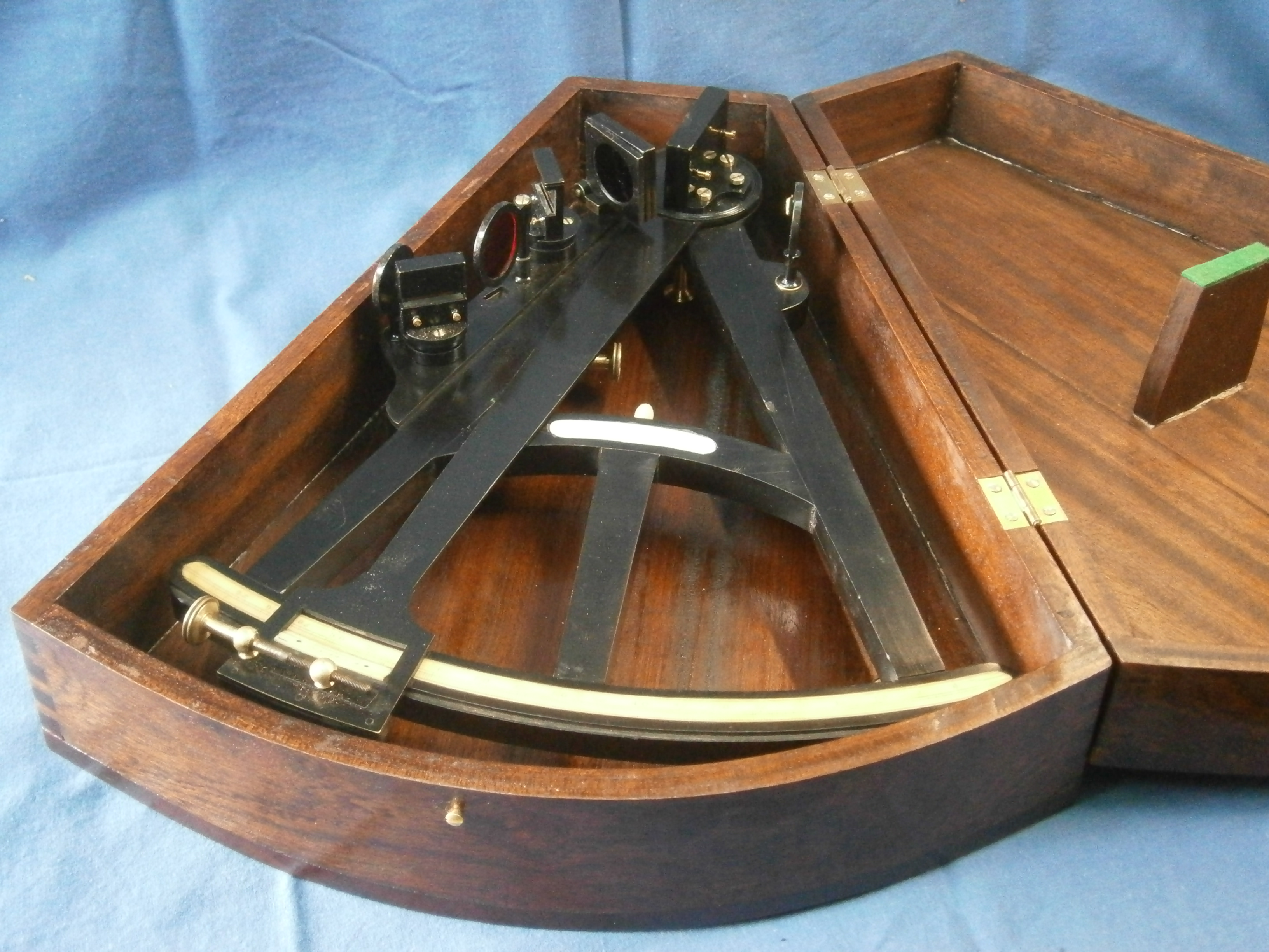
During a lock-down period for Covid 19 in 2021, a large box arrived from a collector in Australia. In it were four antique sextants and a circle which Dave wished me to restore for him and over the intervening months I did just that. A few weeks ago, when New Zealand opened its gates again to overseas visitors, he came to visit his mother, and also made the trip up to the Far North to collect his instruments. During his visit, he was able to look over my few late eighteenth and early nineteenth sextants, and before he left he entrusted me with another sextant and a small box of spare parts, in the hope that I could restore it for display rather than actual use. Figure 1 shows the front or left-hand side of the instrument as received except for the index mirror bracket, which I had cleaned and painted before I had thought about photographing it. I had also removed heavy tarnishing from the scales by dint of patient rubbing with ammonia solution.

Figure 1: Front as found

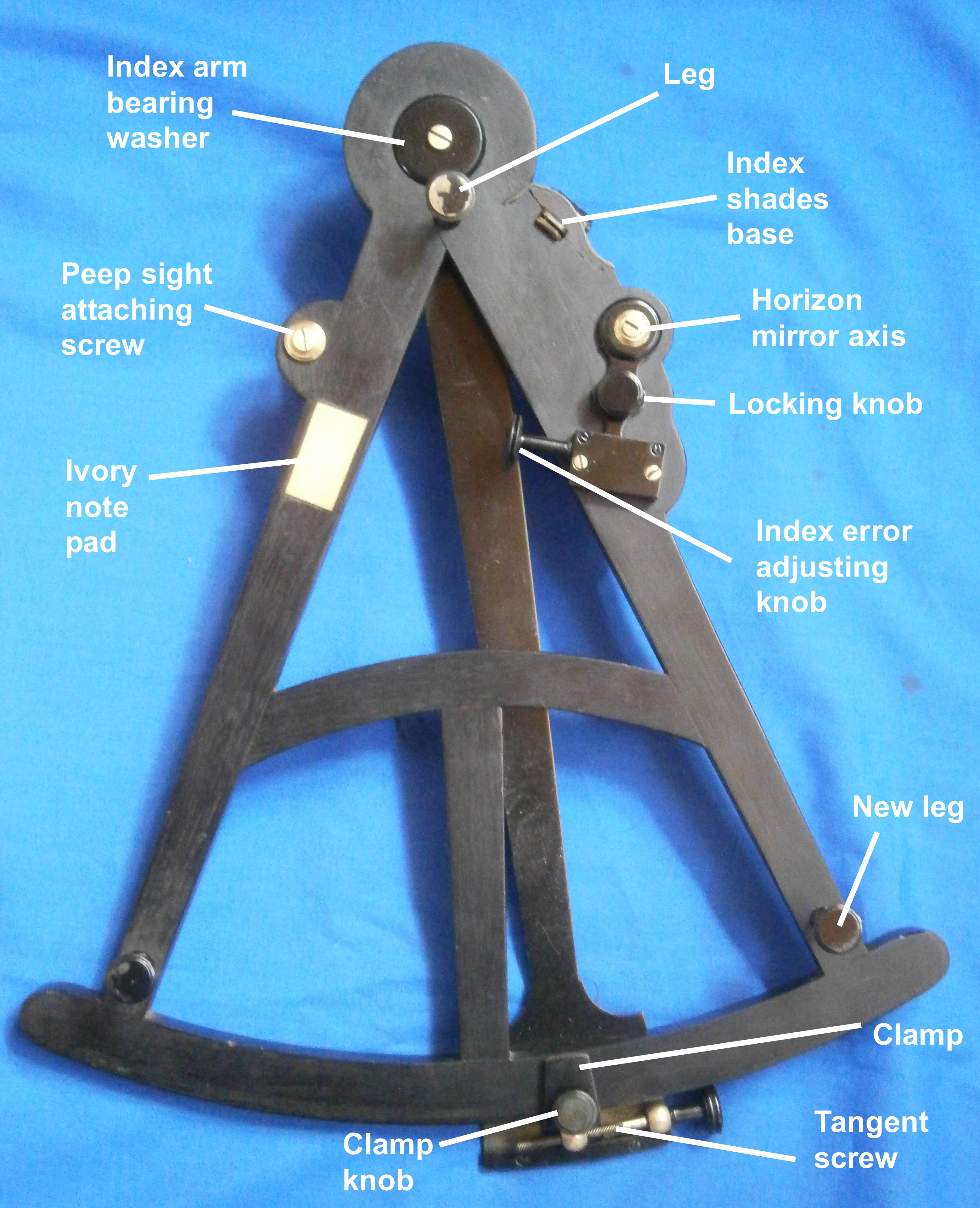
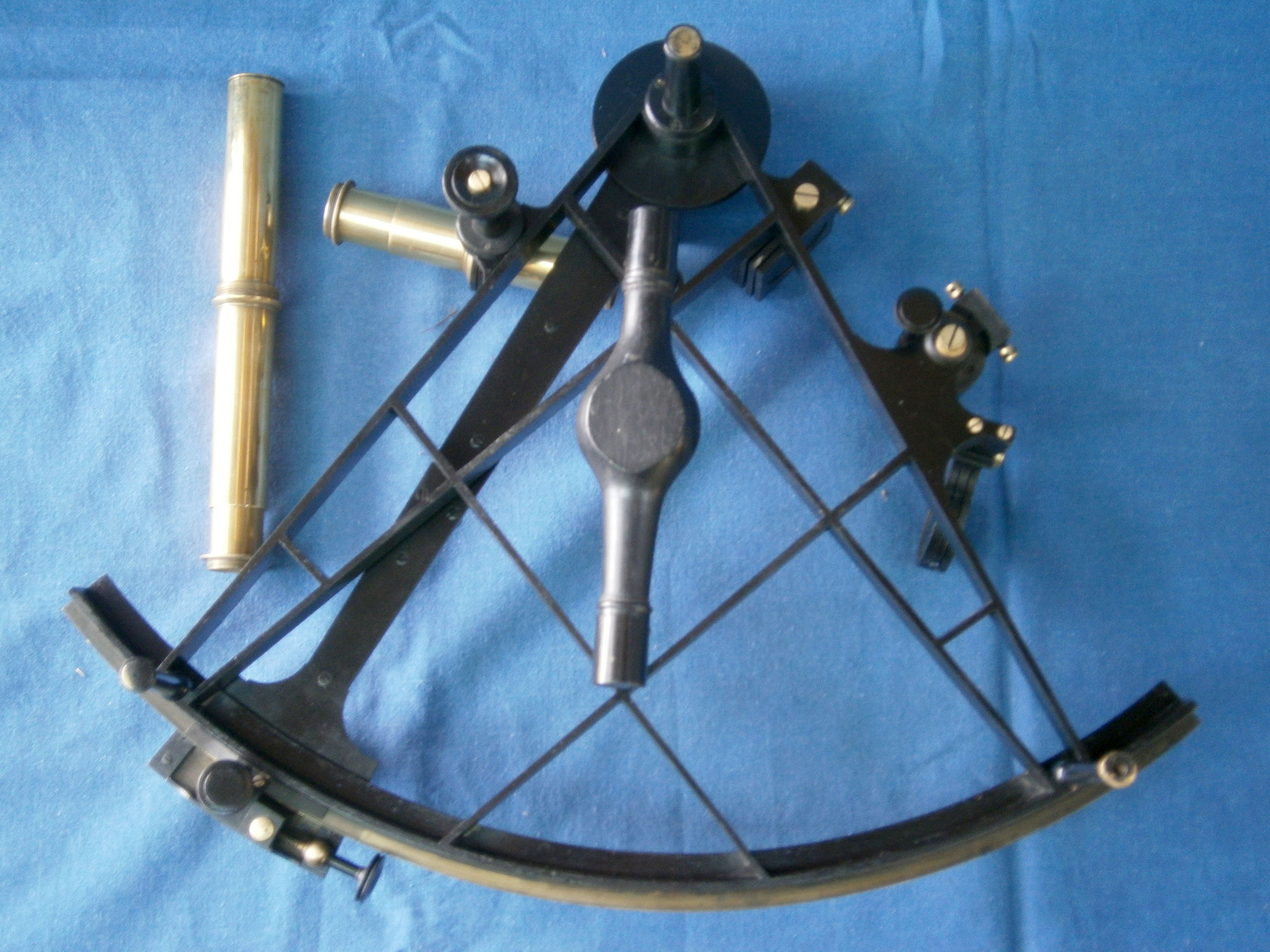
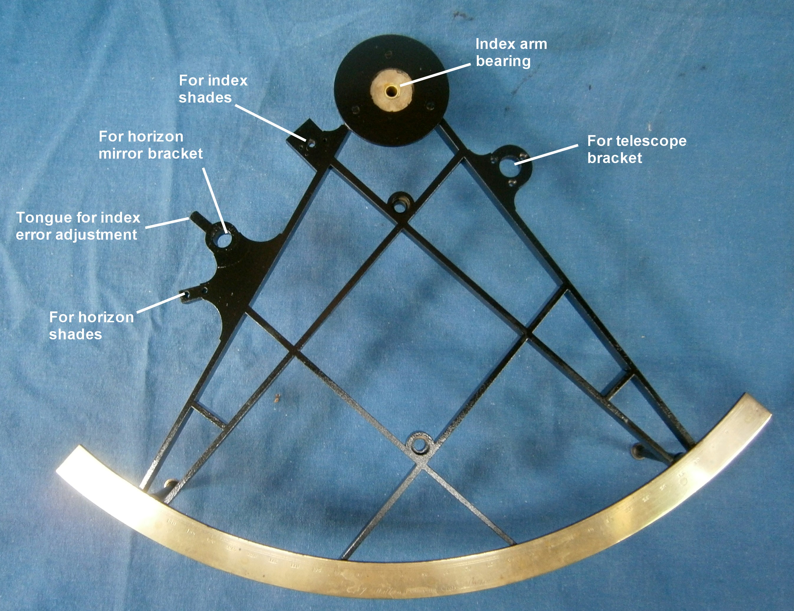
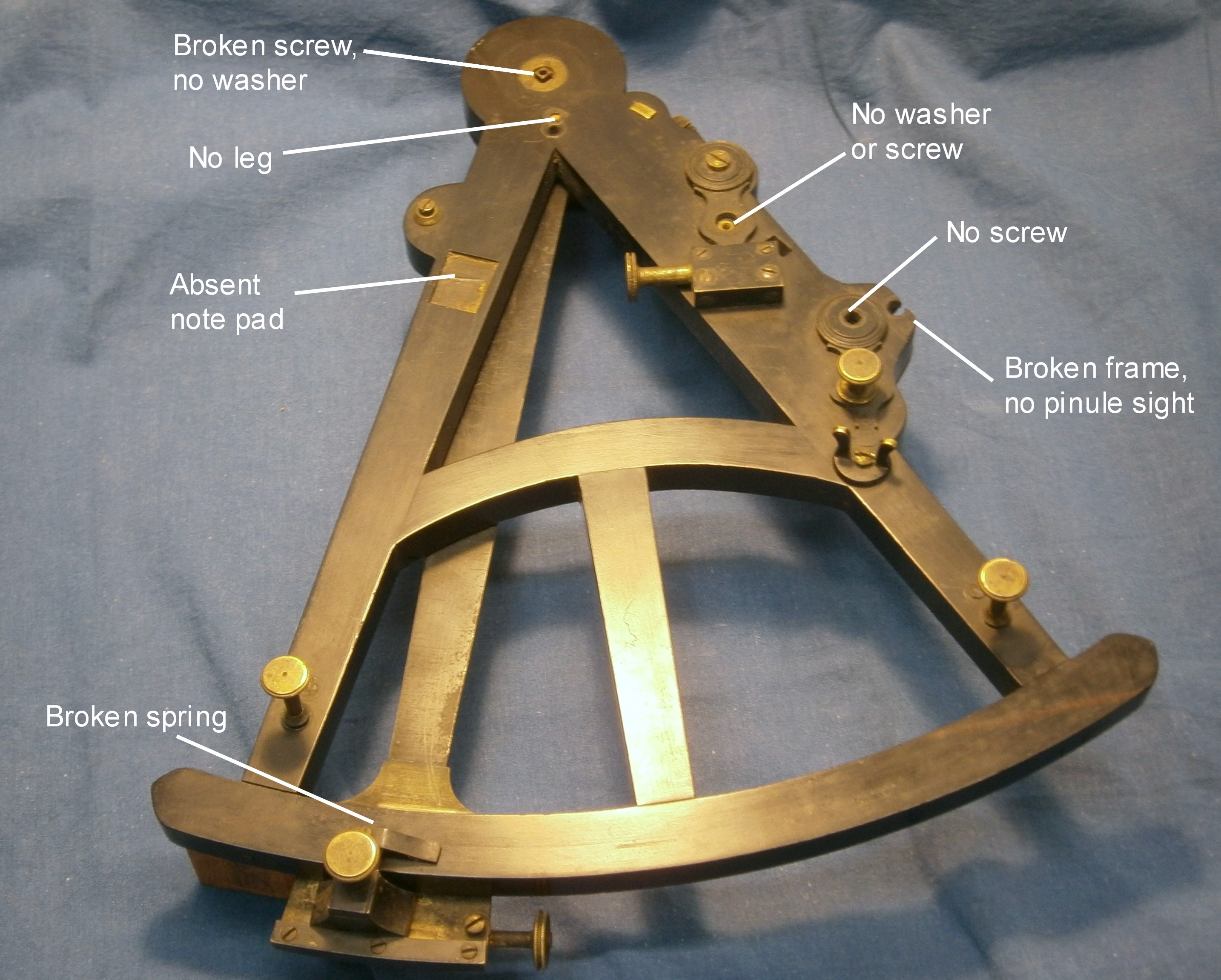
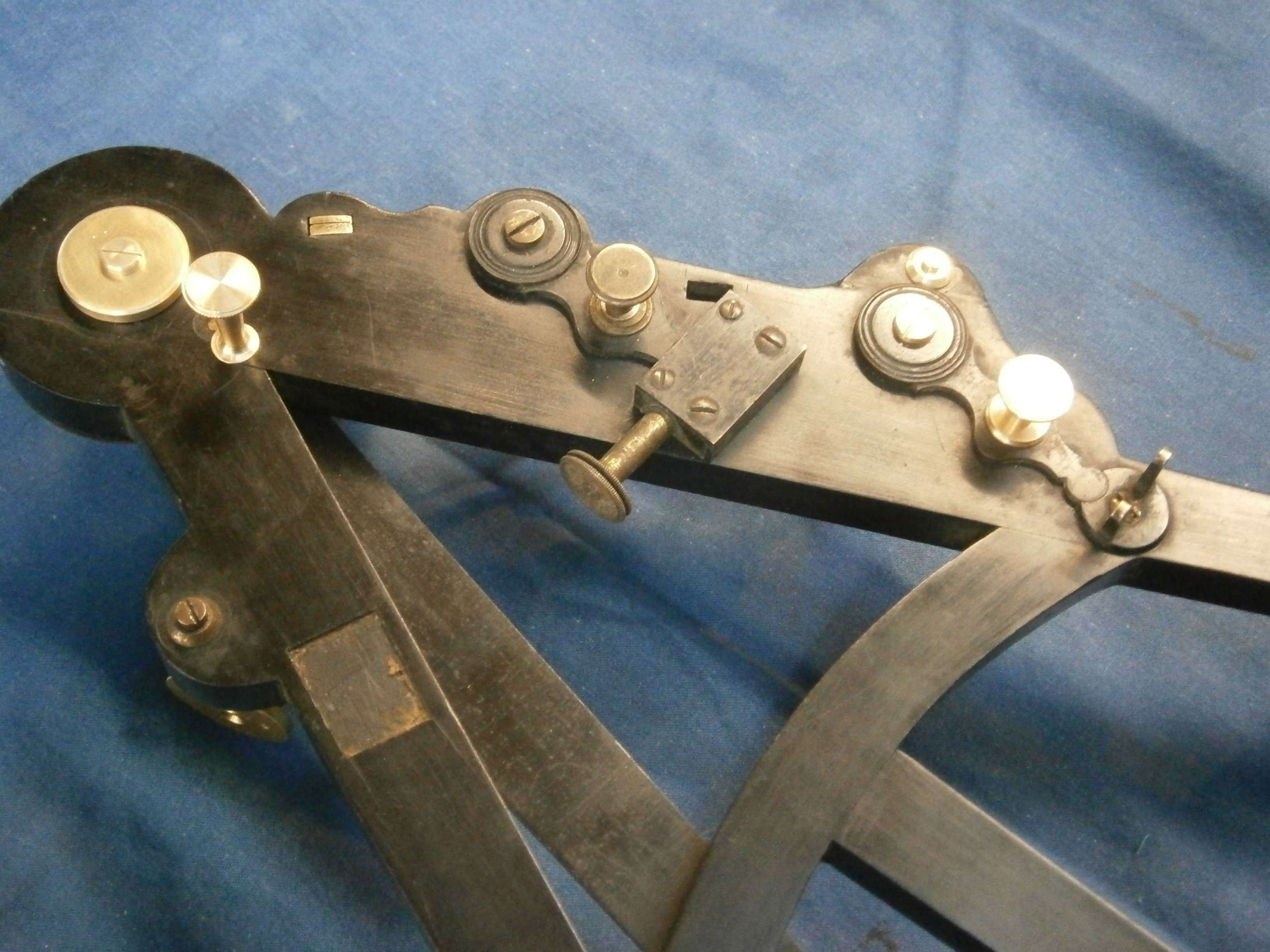
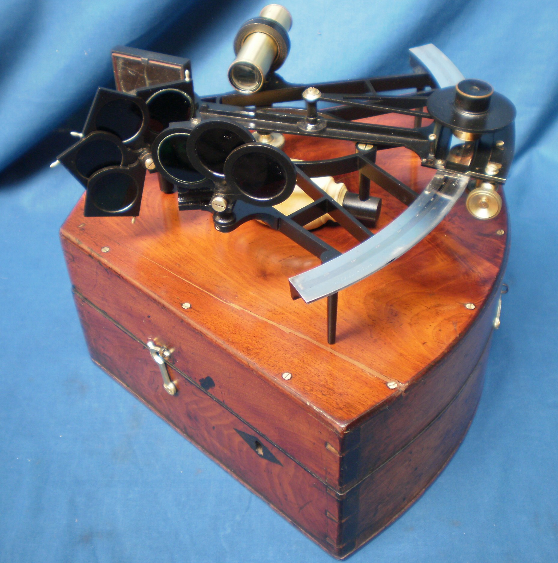
Missing is any form of sighting device, the index mirror bracket, all the horizon shades, the tangent screw assembly and the shade screen for the vernier scale. A thumb screw half way down the index arm marks where a magnifier arm for reading the scales was no doubt placed. Figure 2 shows the rear or right-hand side as found.

Figure 2: Rear as found

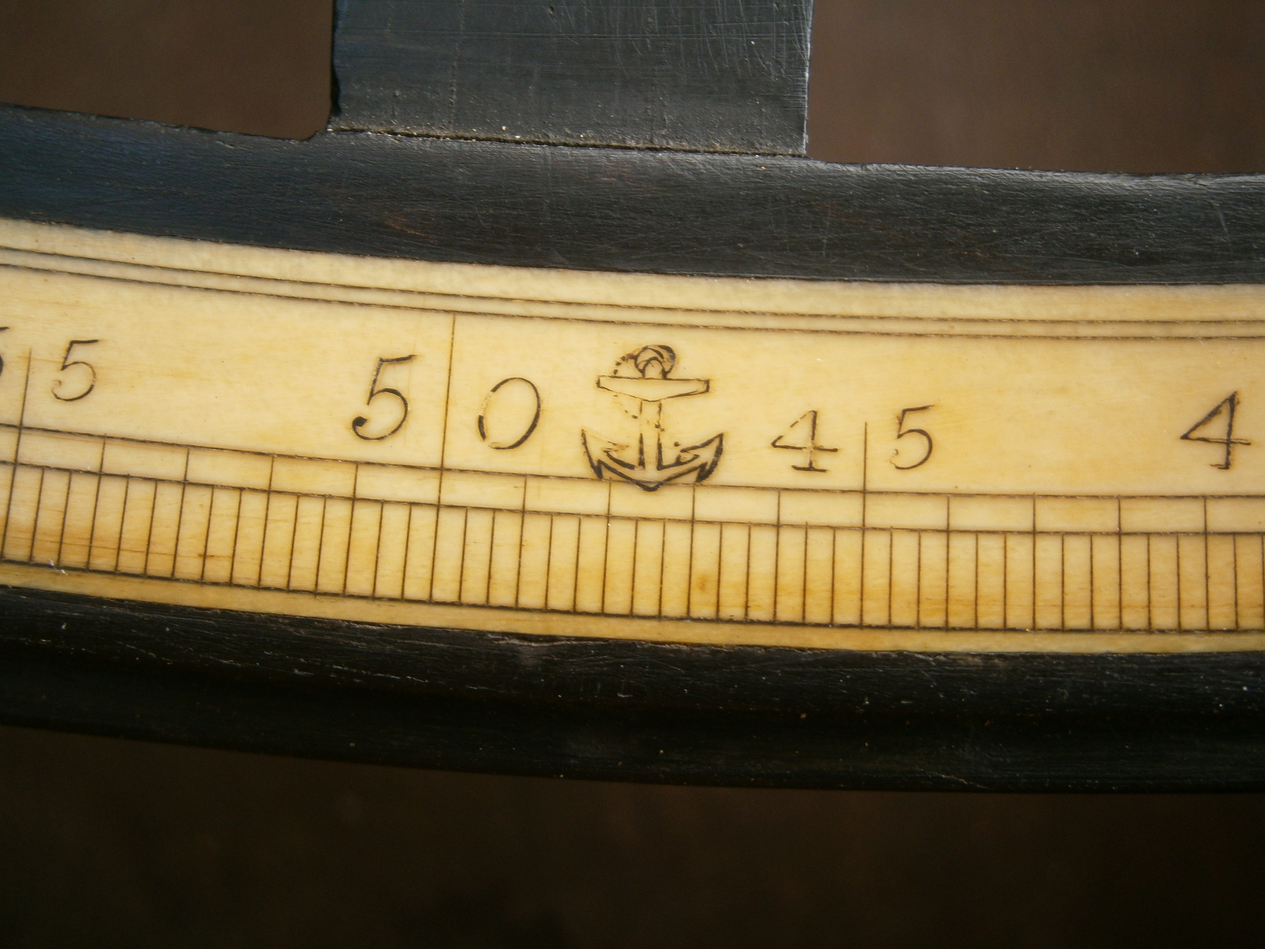
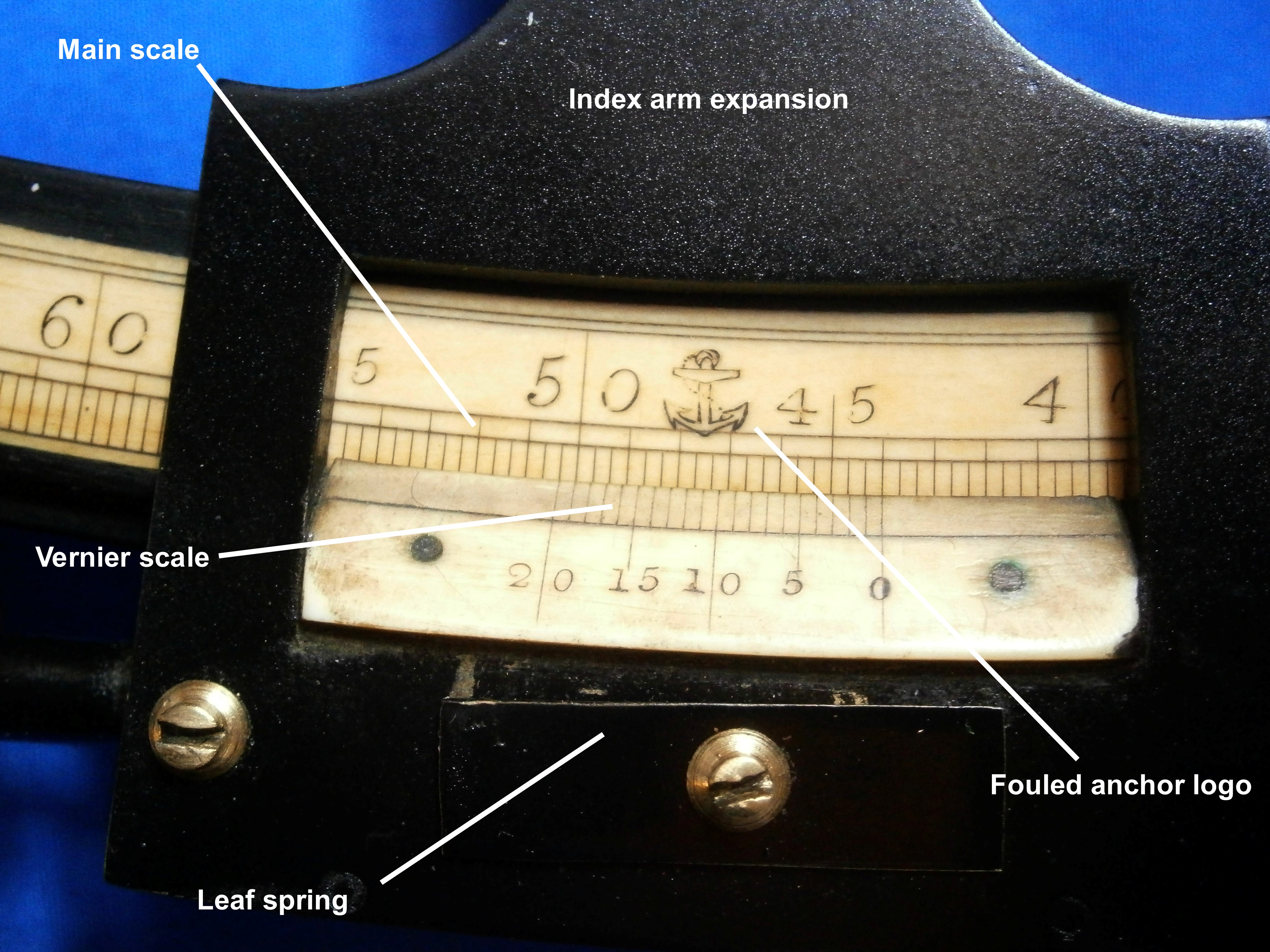
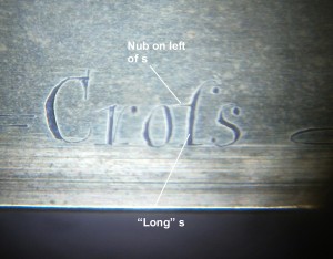
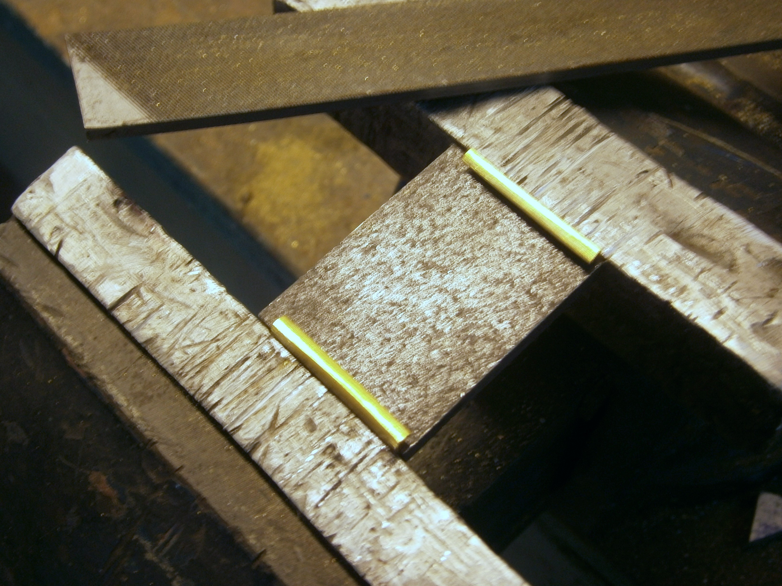
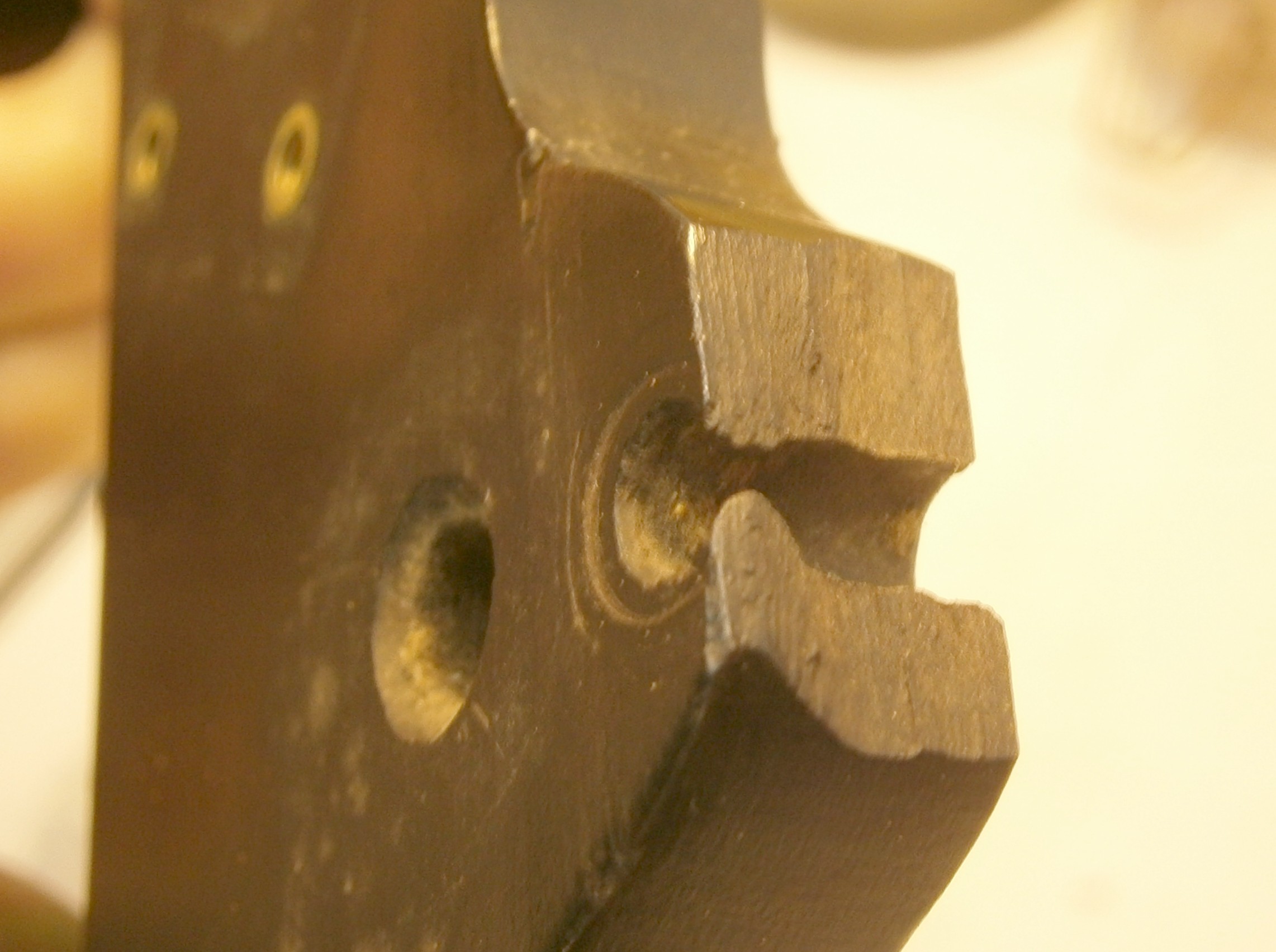
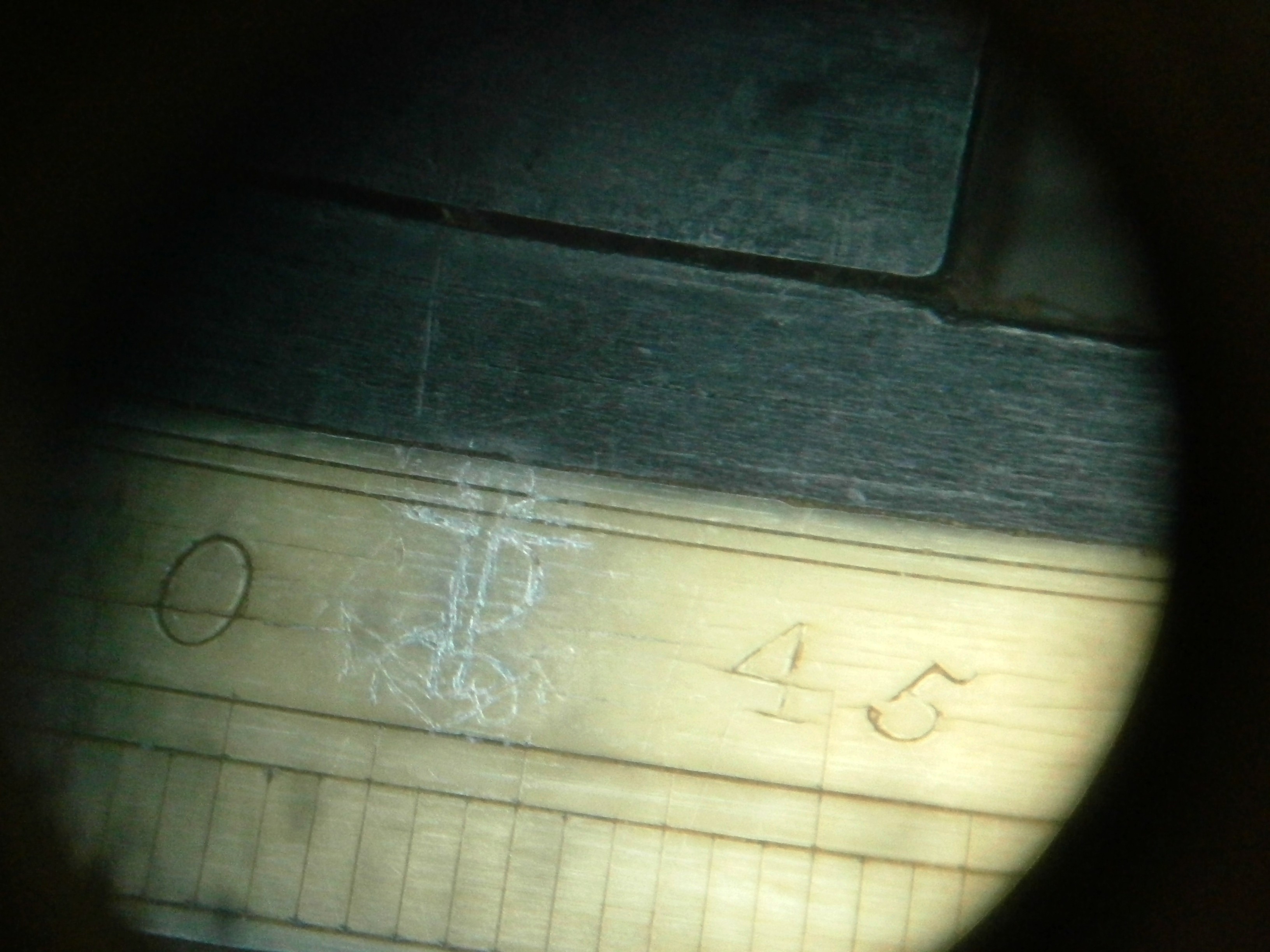
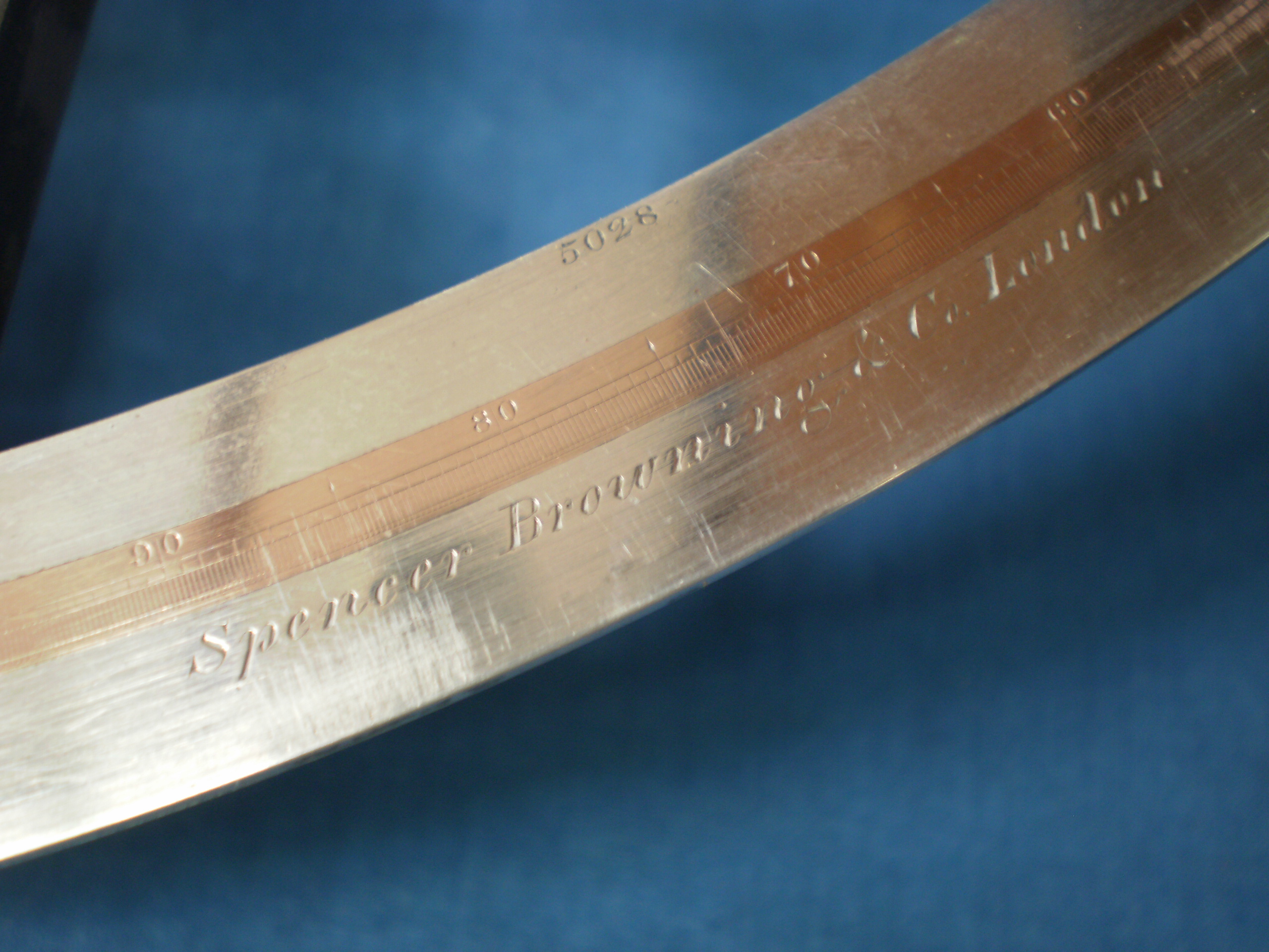
It is somewhat unusual to find a silver-in-brass arc married to a wooden frame, in this case of heart ebony, a strong, dense and stable African hardwood. More usually, wooden framed sextants have ivory arcs glued in a rebate on the front of the limb, while early metal-framed sextants commonly had ivory arcs inlaid. Figure 3 shows one of the nine rivets that attach the arc to the frame and the maker’s name. I have not been able to find any details of Védy of Paris or indeed, whether he was a maker or merely a retailer. The fact that the instrument is numbered suggests the former. Perhaps some reader can tell me more?

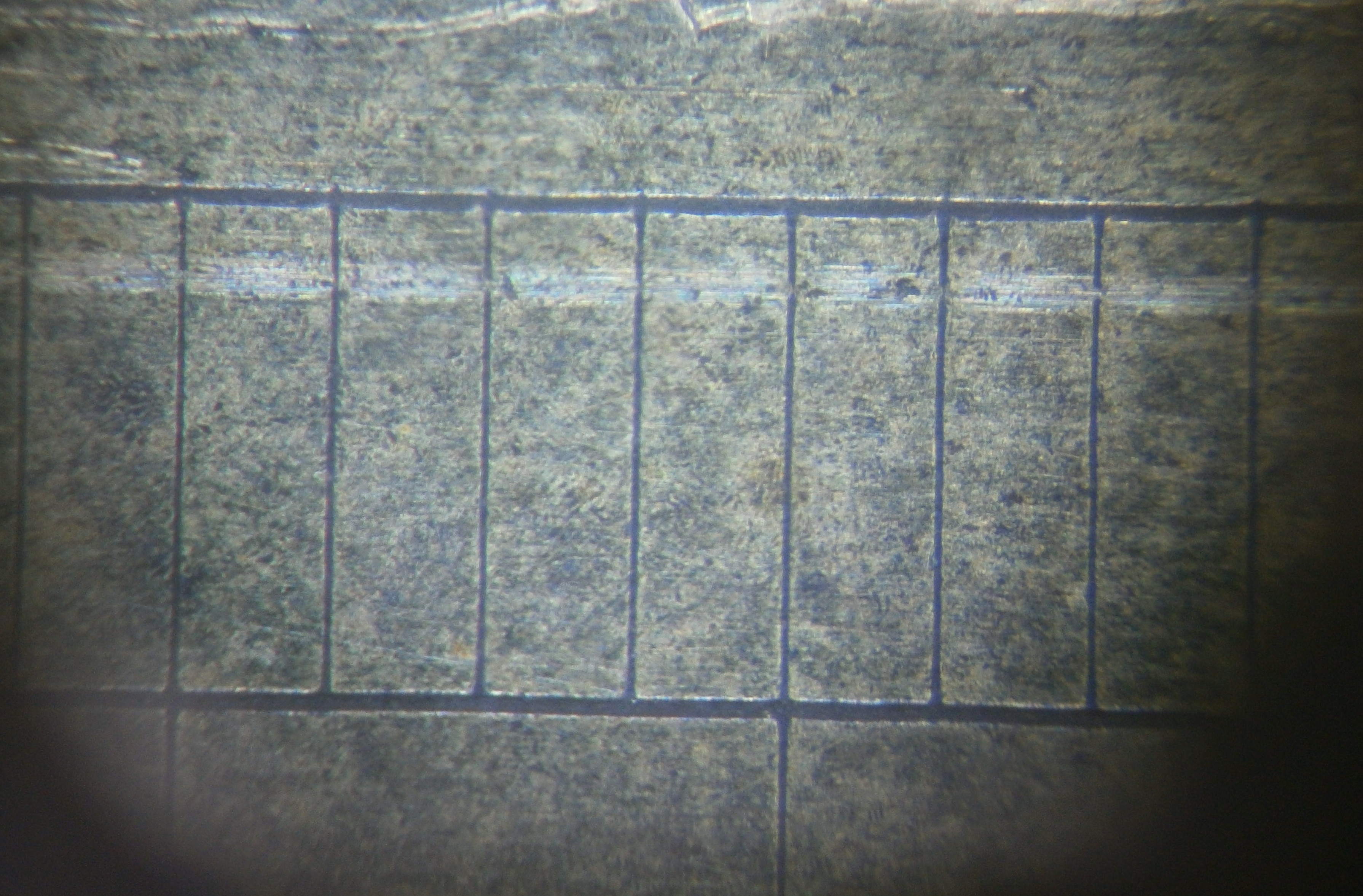
The dividing of the scale is of high quality and it is known that Bochard de Saron acquired Jesse Ramsden’s first dividing engine in 1775 and made it available to French artisans until he literally lost his head in April, 1794, during the French Revolution. The state then continued to make it available to instrument makers, including the leading maker, Etienne Lenoir.

Figure 3: Main scale and name.

The mirror adjustments are complex and archaic at a time when most sextants of English manufacture had adopted the simpler method described by Peter Dolland in 1772 in a letter to the Astronomer Royal, Nevil Maskelyne, and published in Phil. Trans. 1772 62, 96 – 98. It was also described in Patent no. 1017 of 22 May 1772. “I have contrived the frame , so that the glass lies on three points, and the part that presses against the front of the glass has also three points exactly opposite to the points between which the glass is placed. This contrivance may be of some use; but the principal improvements are in the methods of adjusting the glasses,...” The method not only removes stresses in the mirror but also allow for simple adjusting of perpendicularity of the index mirror and removal of side and index error at the horizon mirror.

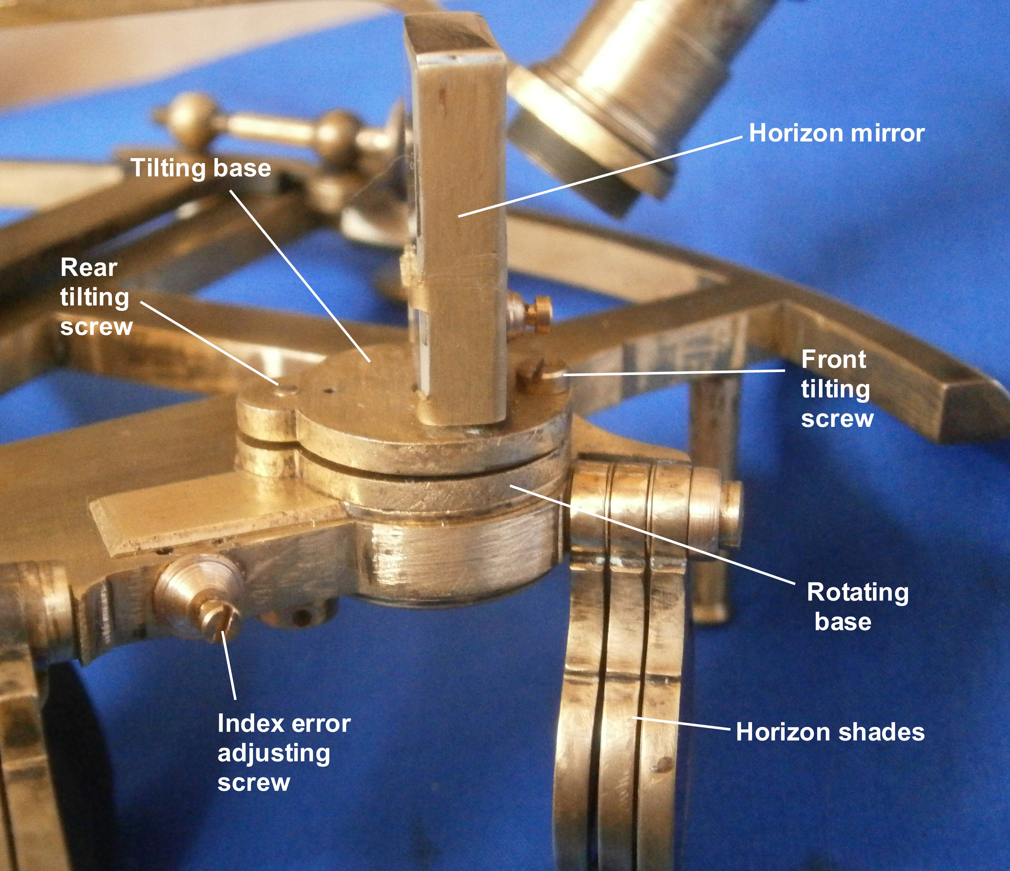
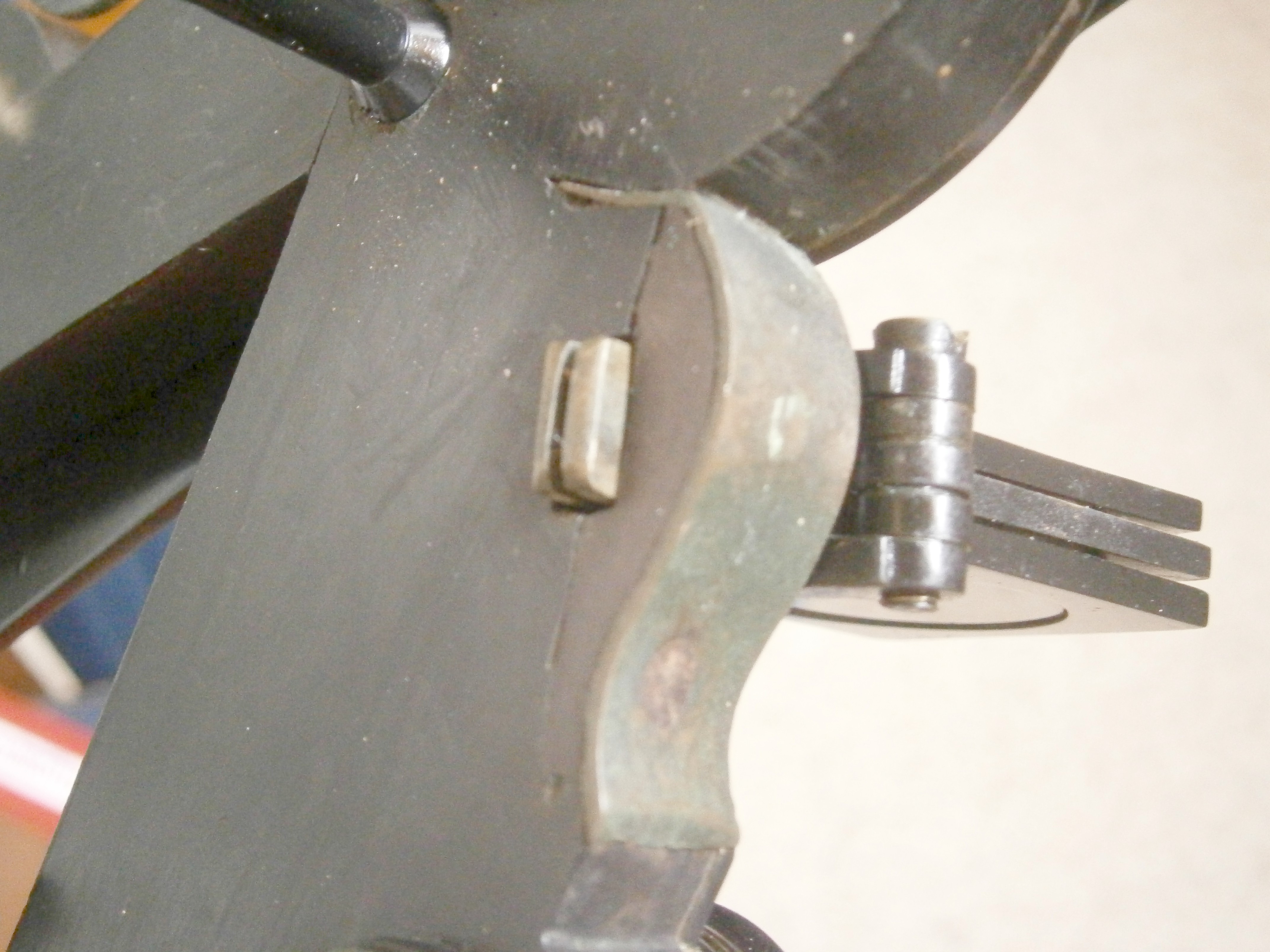
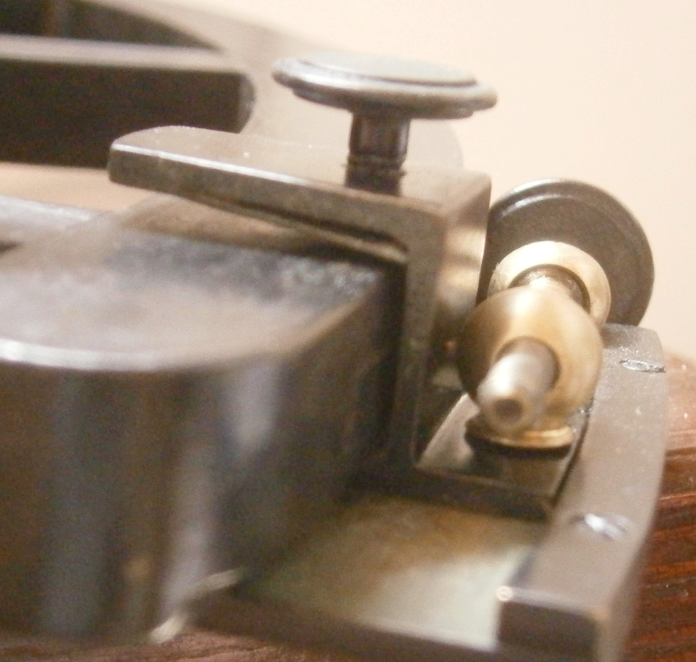
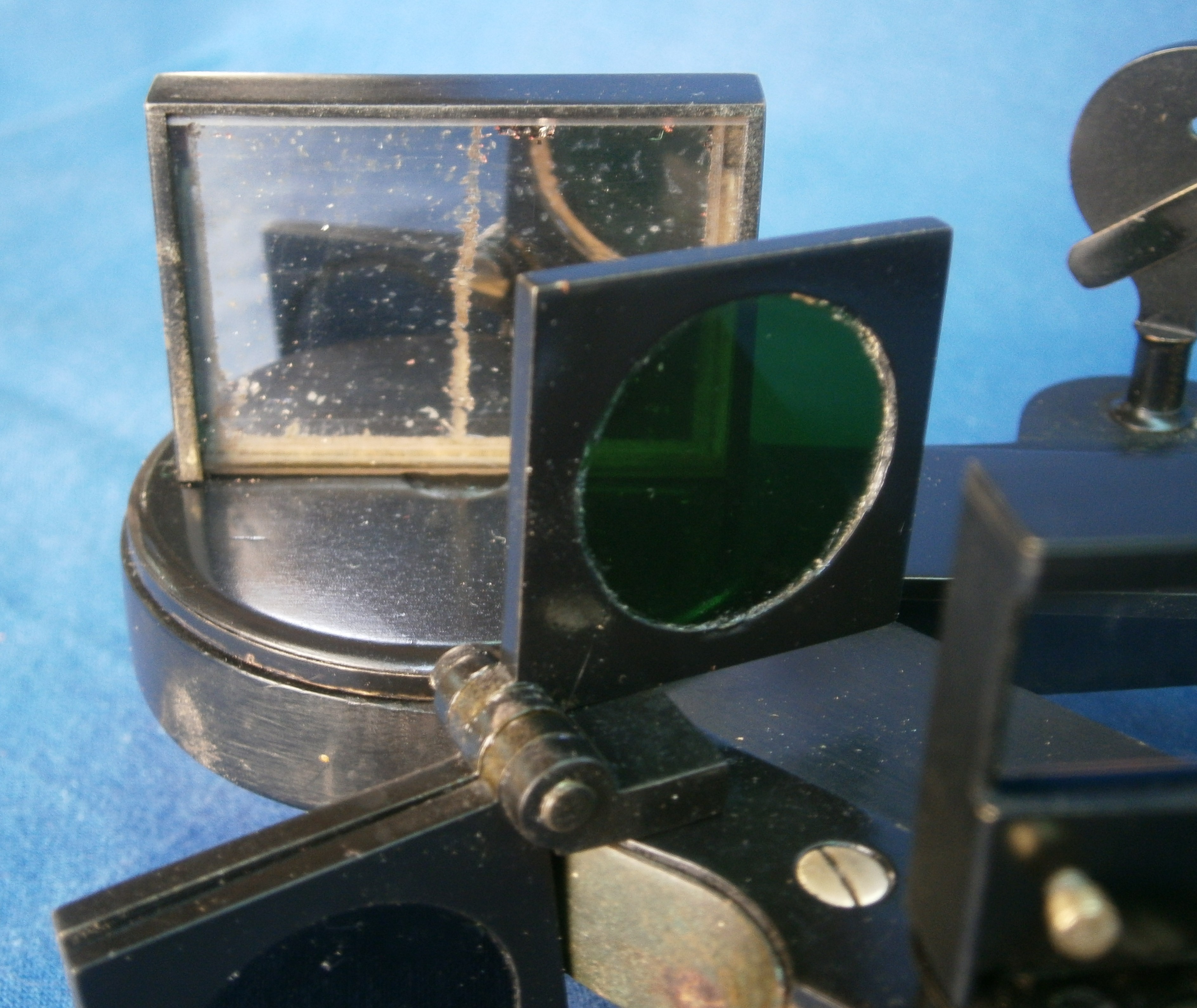
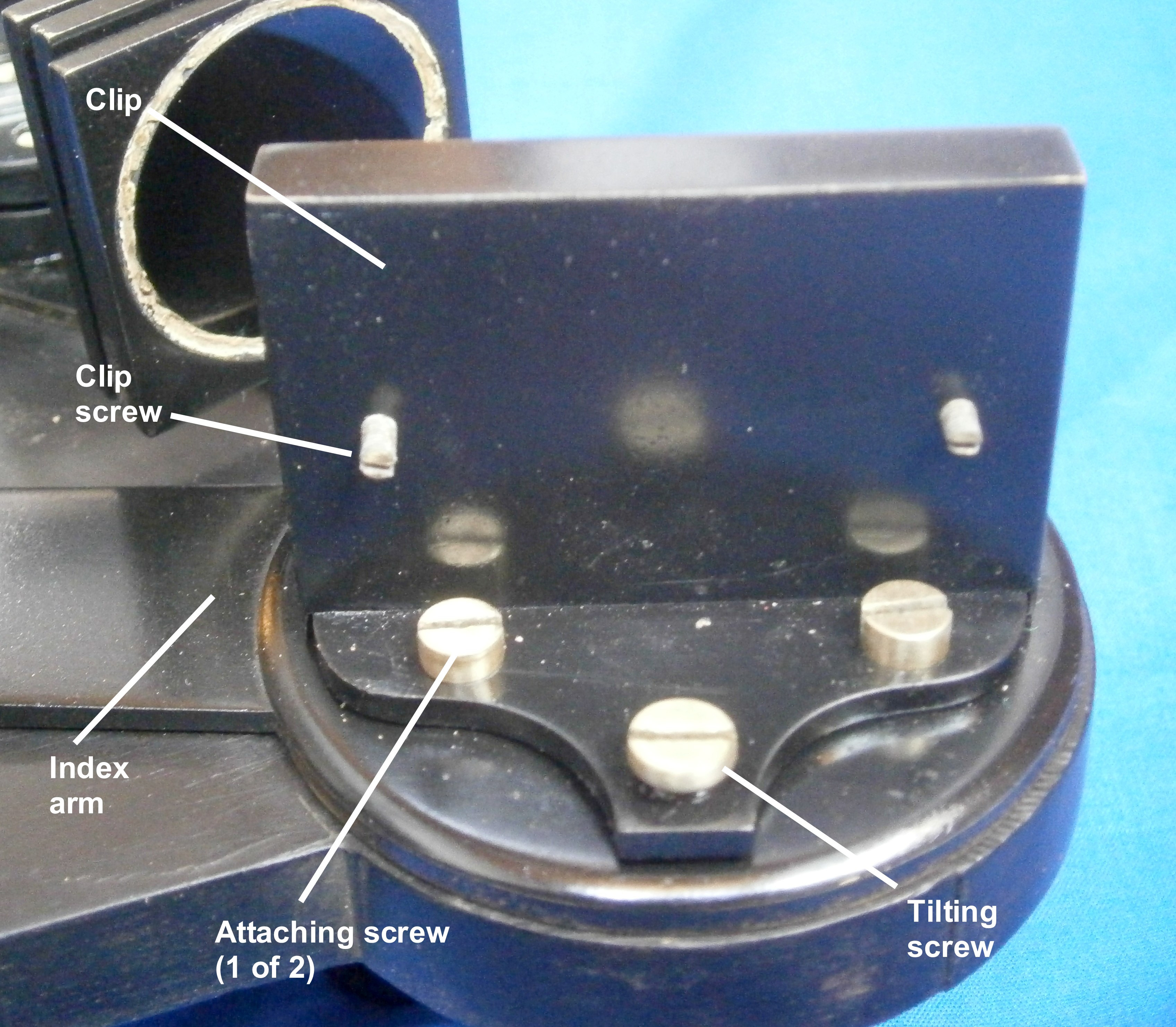
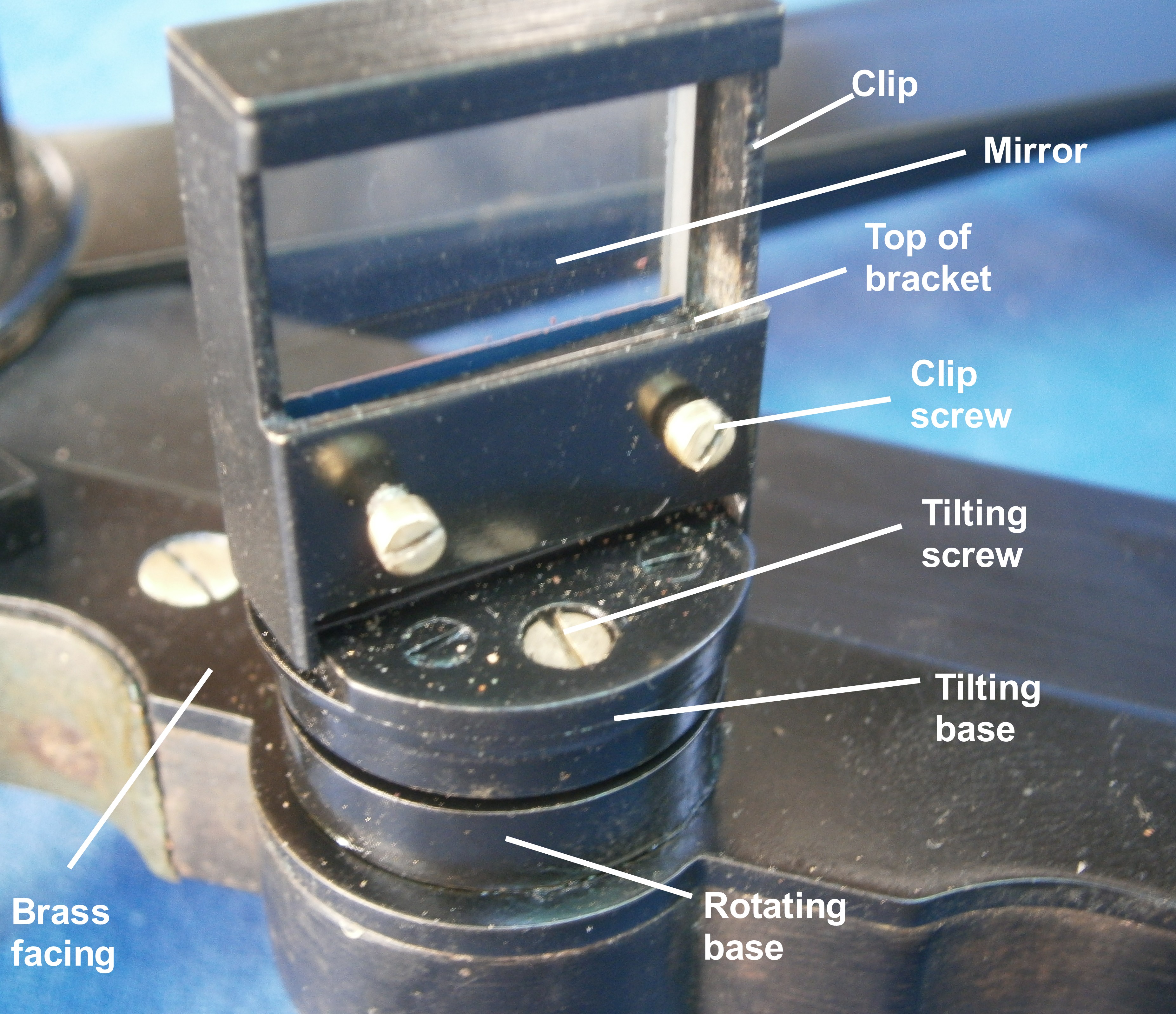
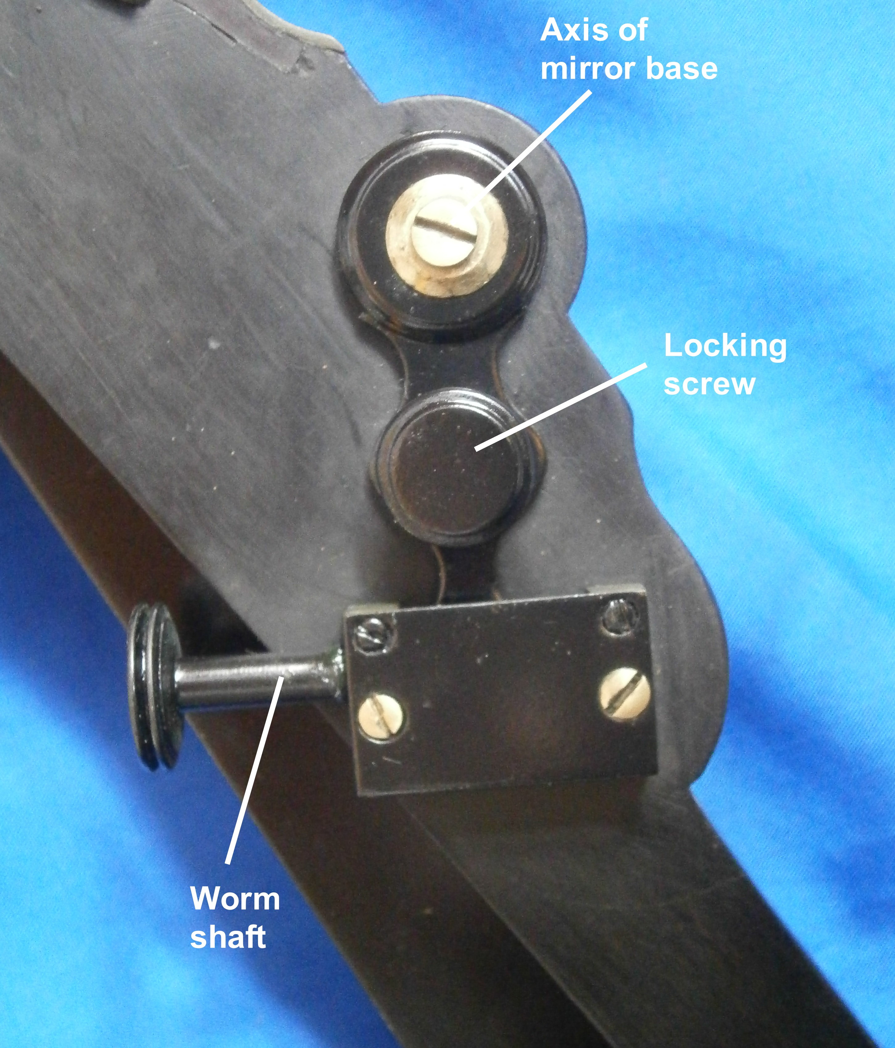
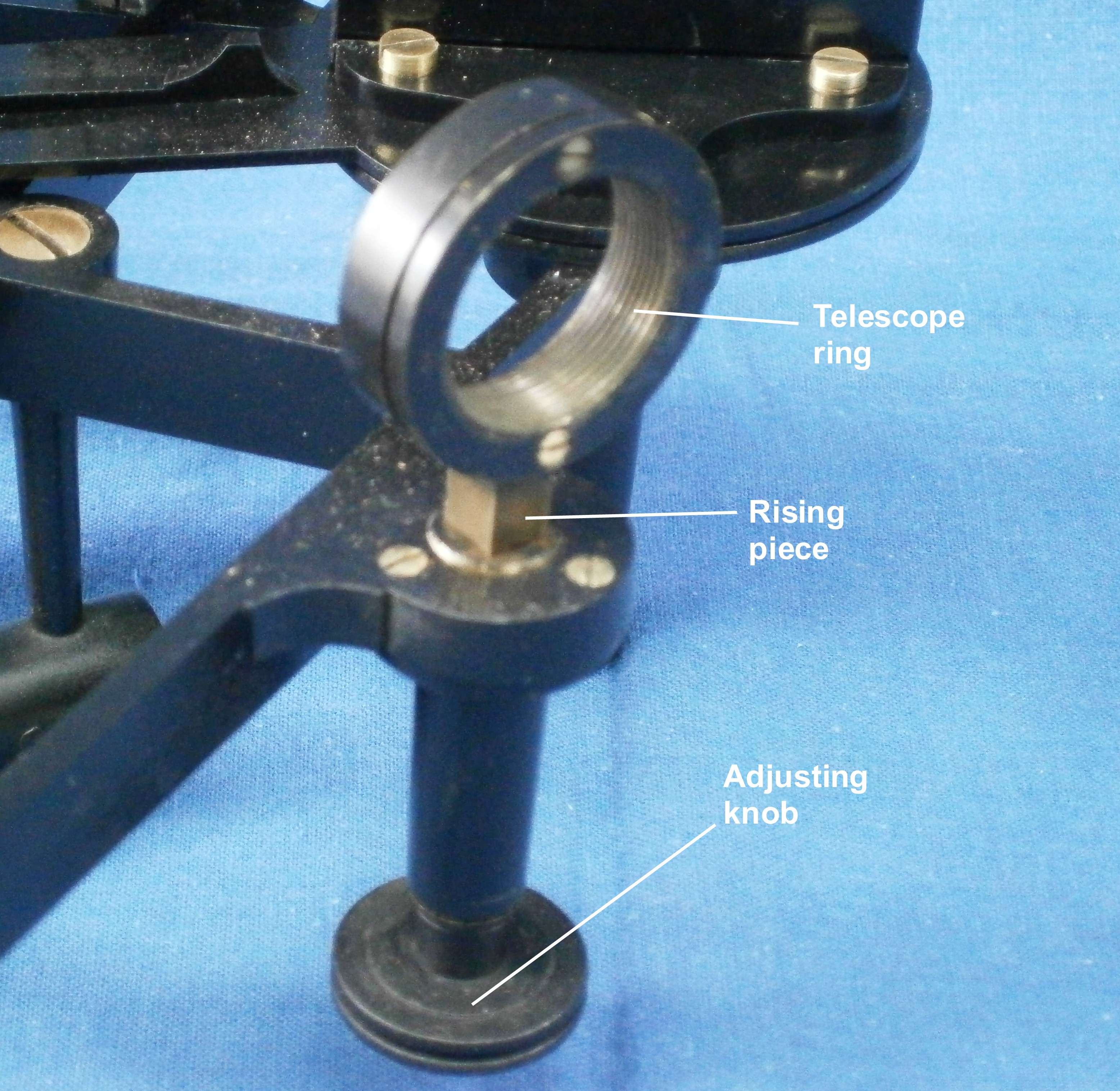
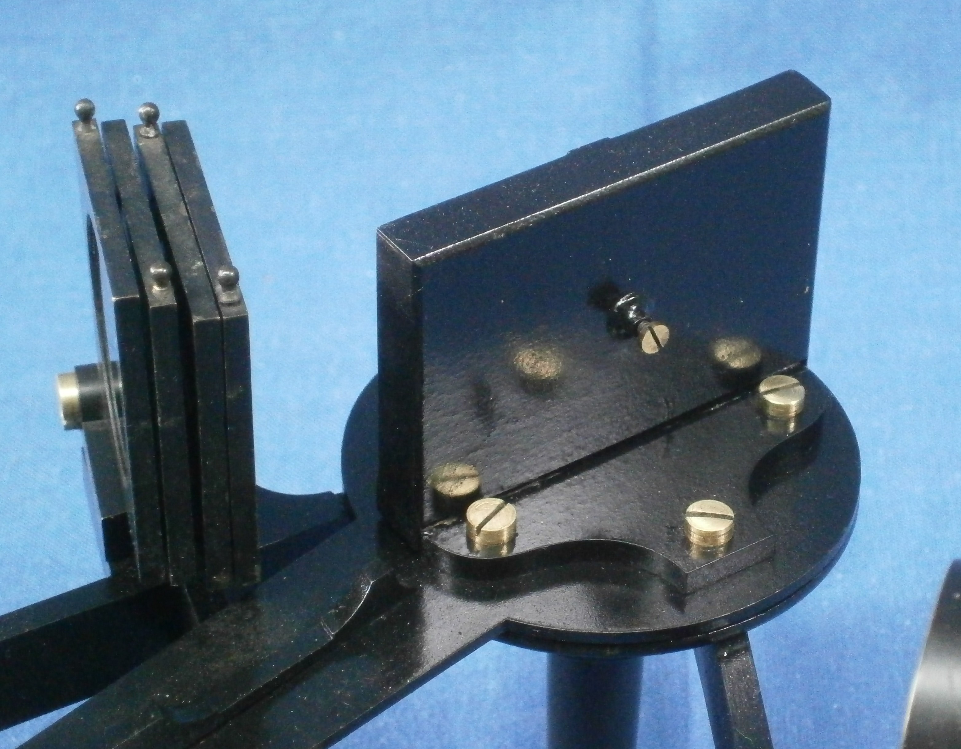
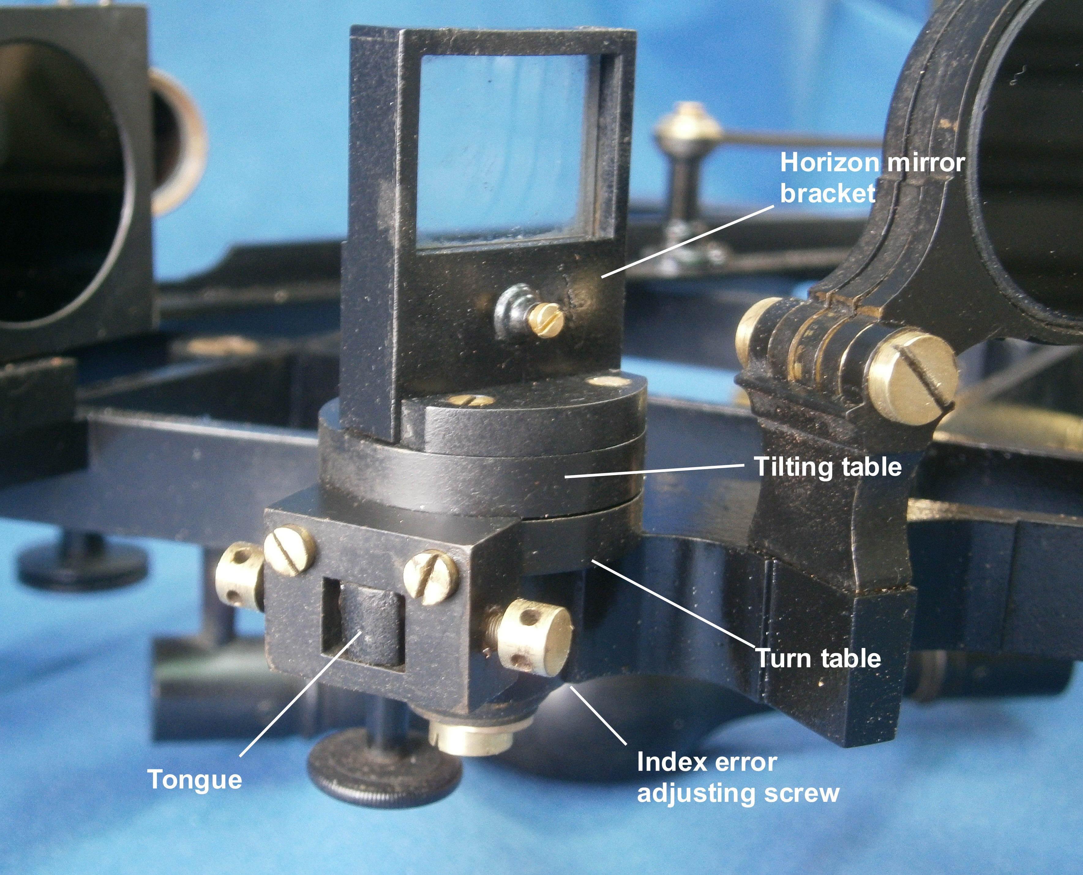
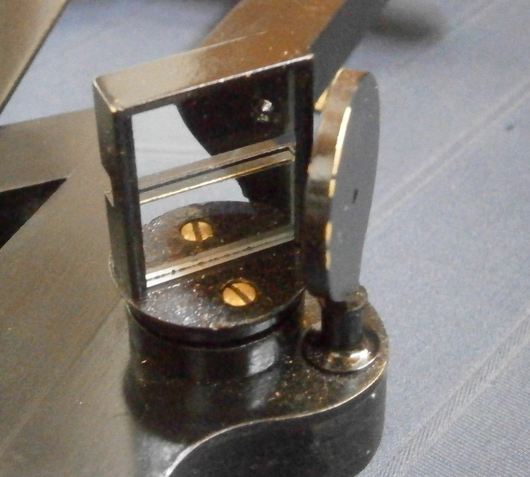
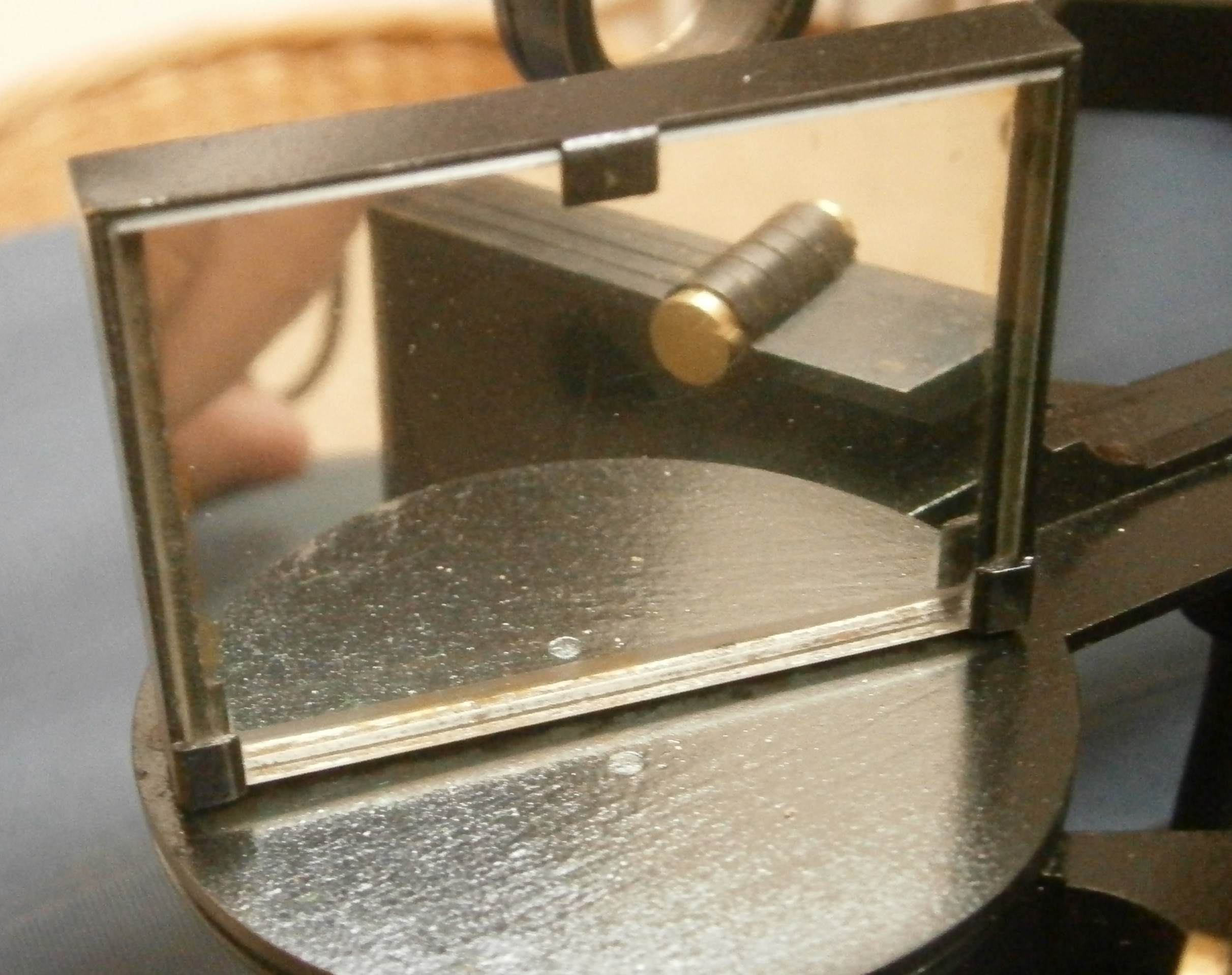
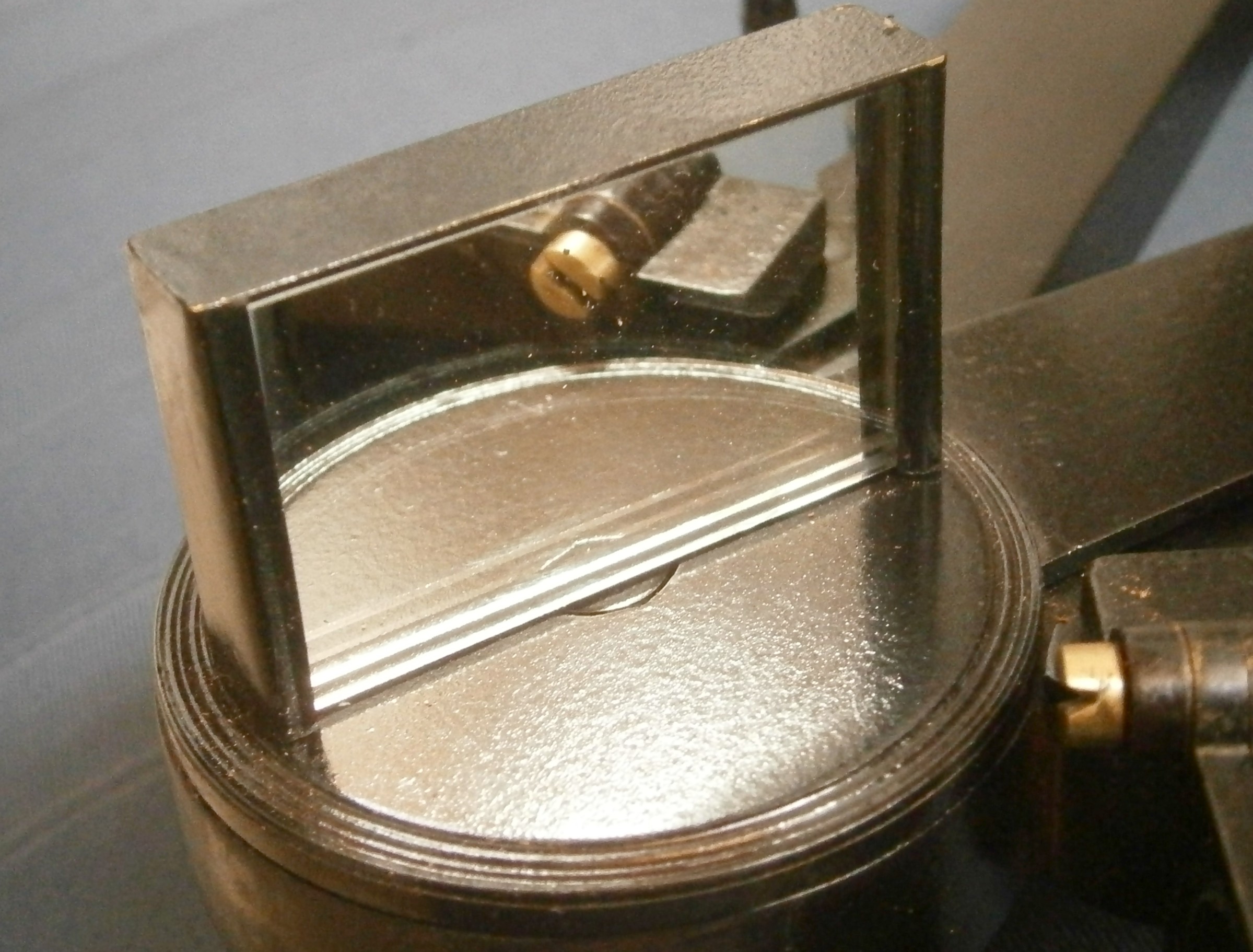
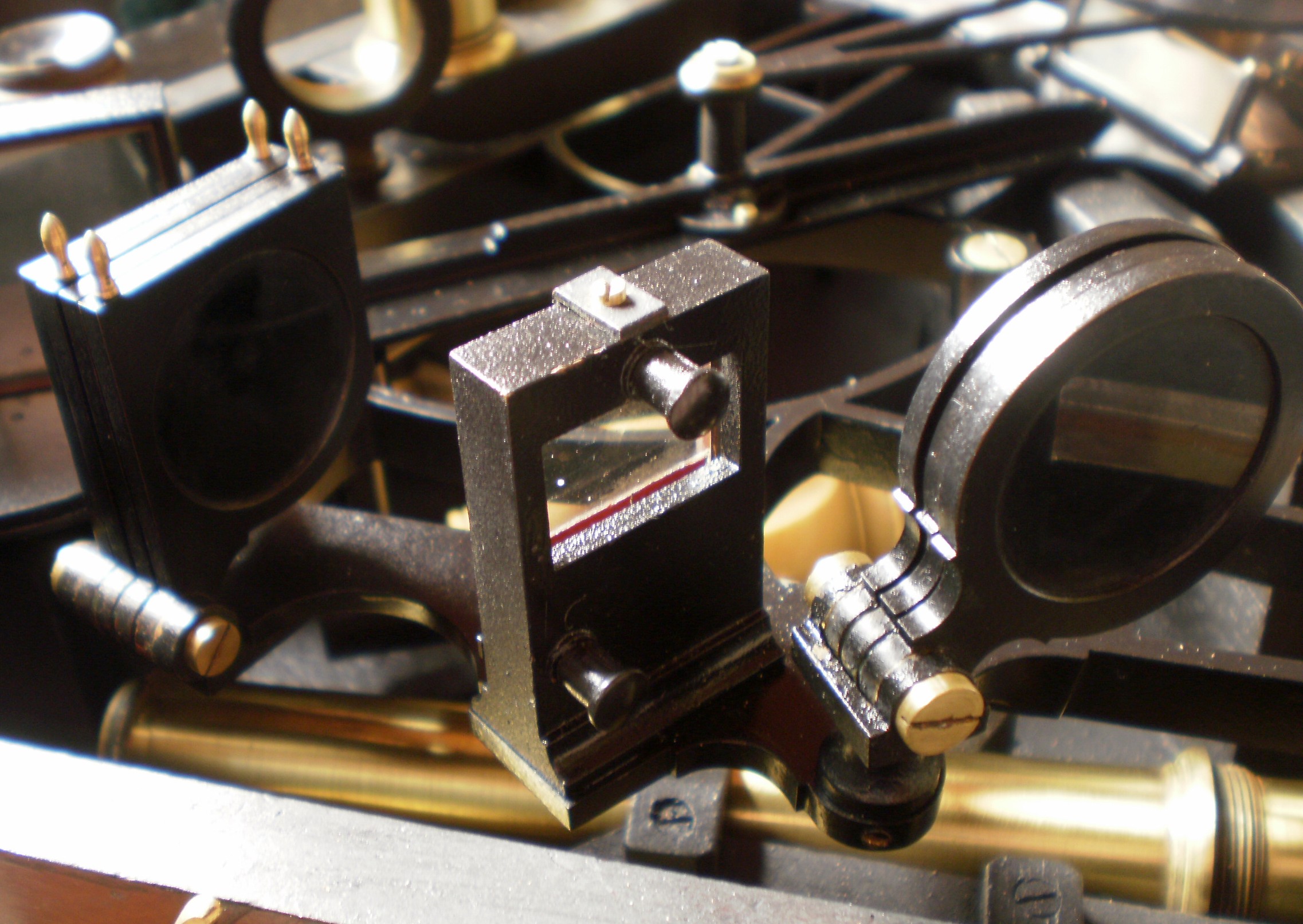
Figure 4 shows the means of adjusting out side error. The horizon mirror is held against a vertical bracket on top of a round base by means of a clip and two screws. The base is hinged on to a rotating base the shaft of which extends through the frame to a means of adjustment to be described below. An adjusting screw operates against a spring that surrounds it, allowing the base to be tilted and the mirror made parallel to the index mirror.

Figure 4: Means of correcting side error.

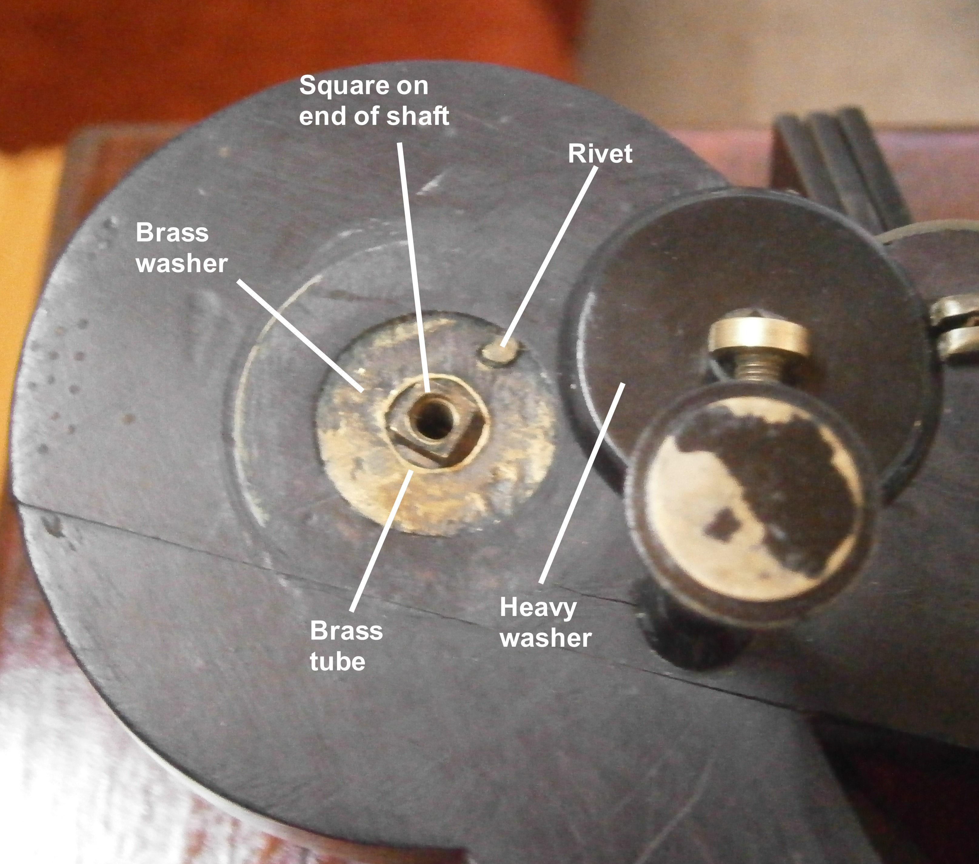
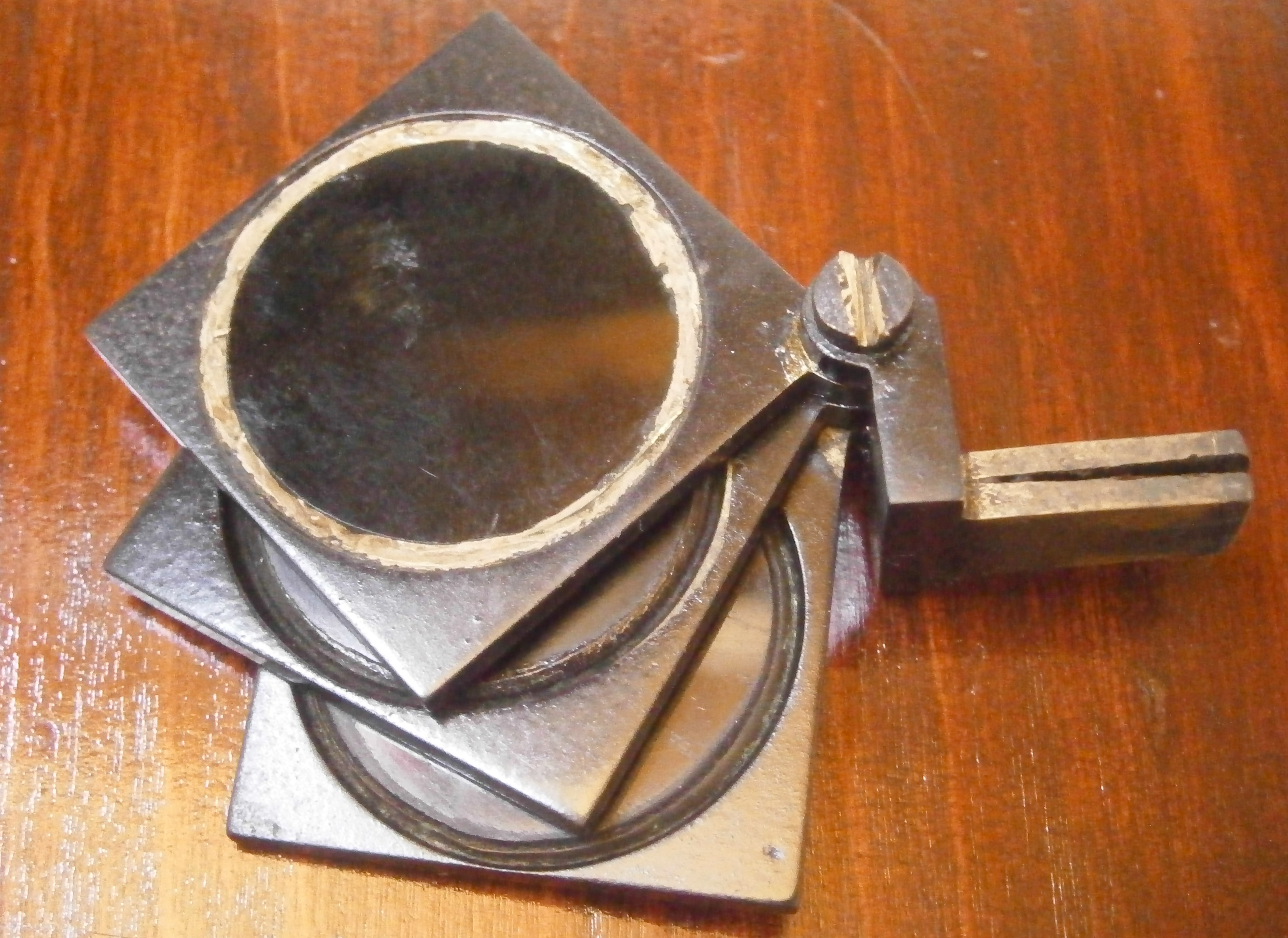
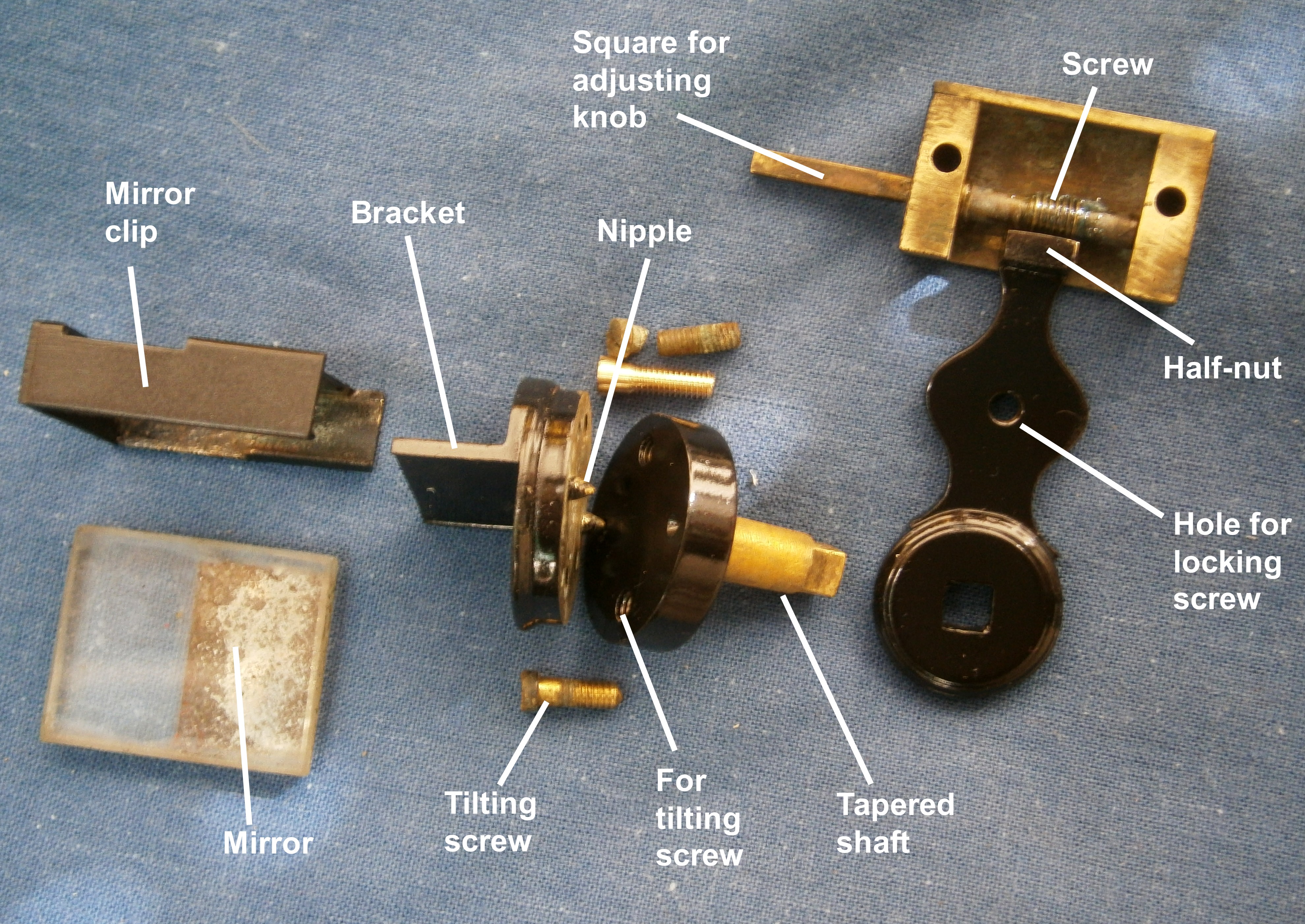
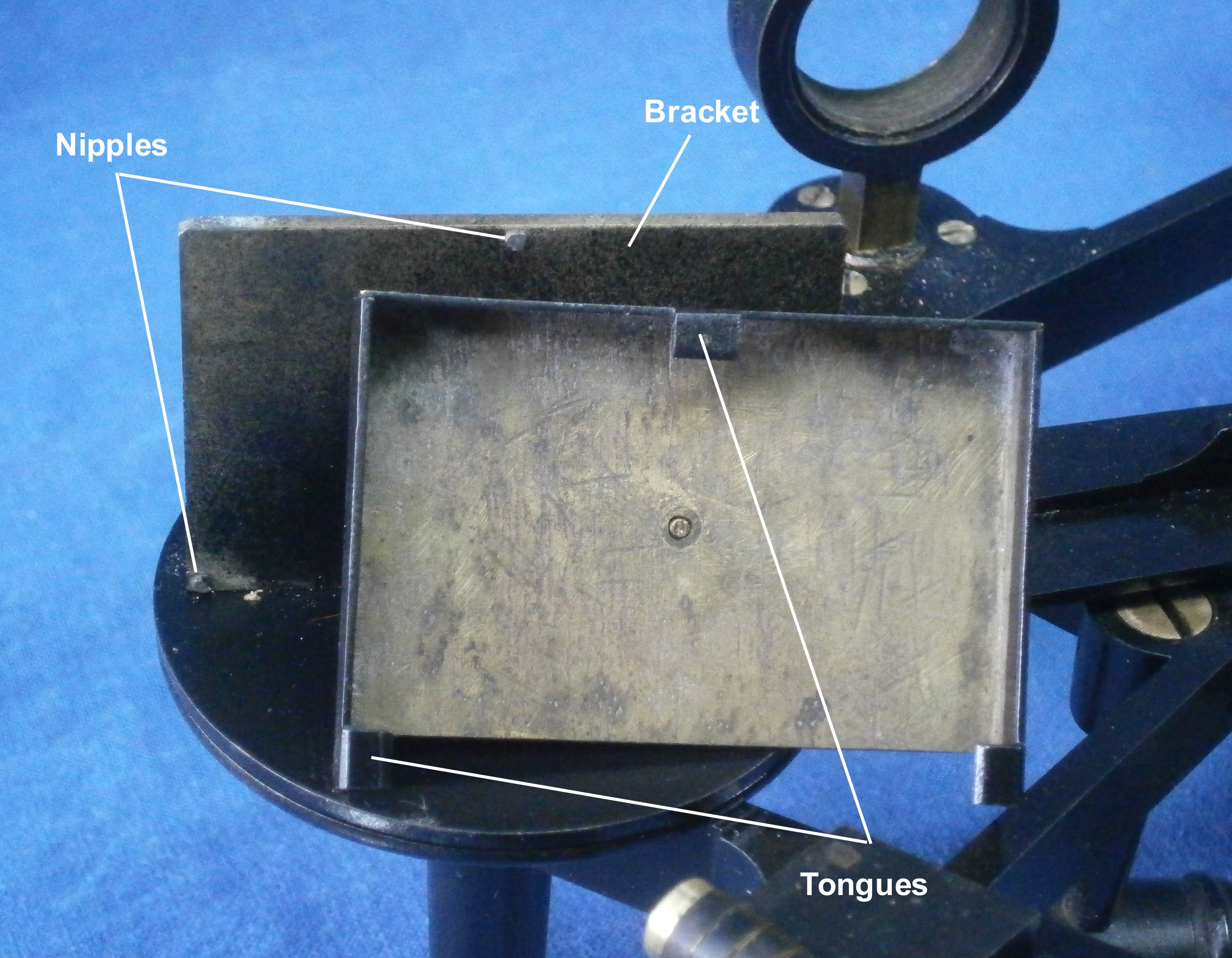
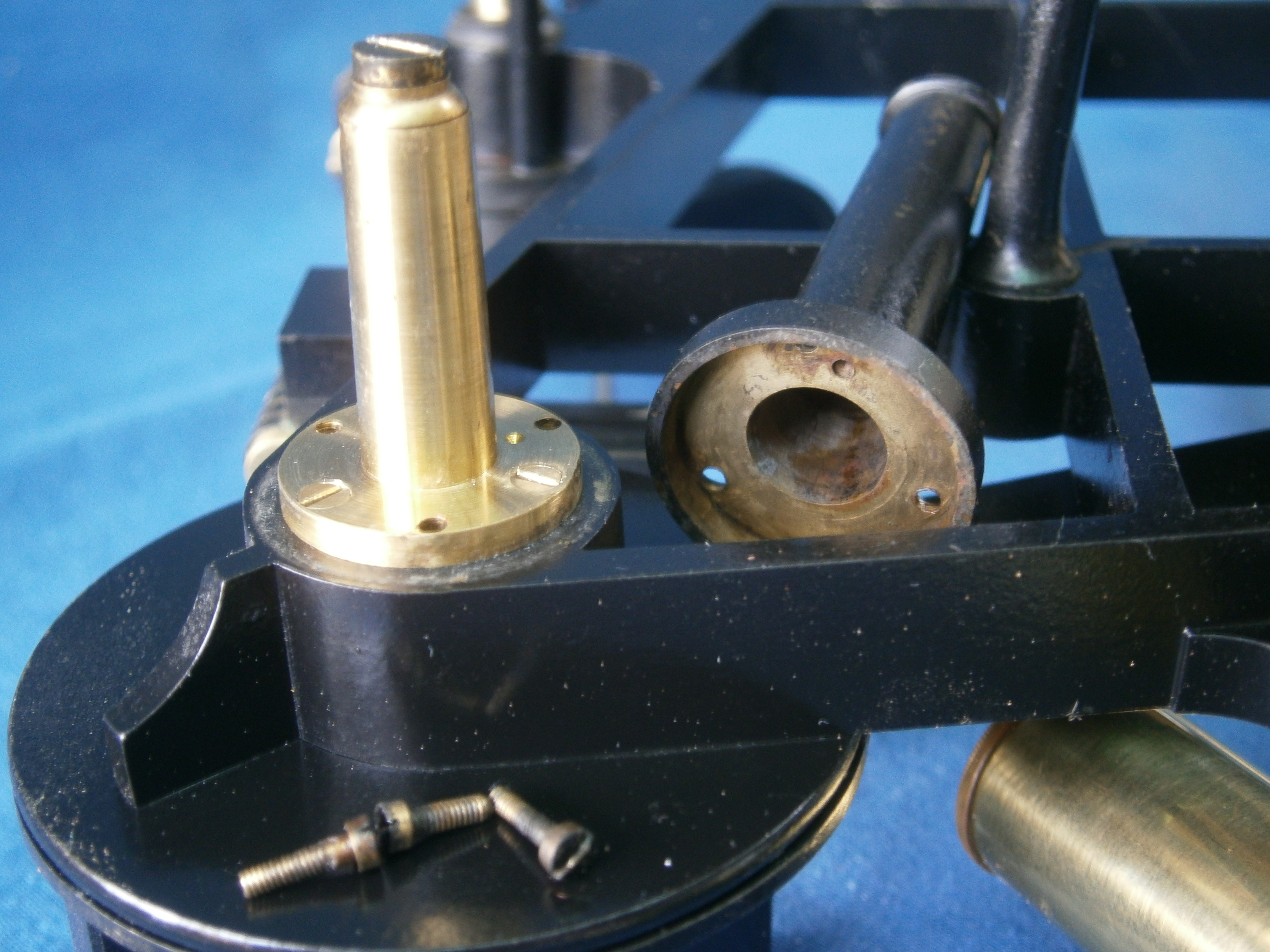
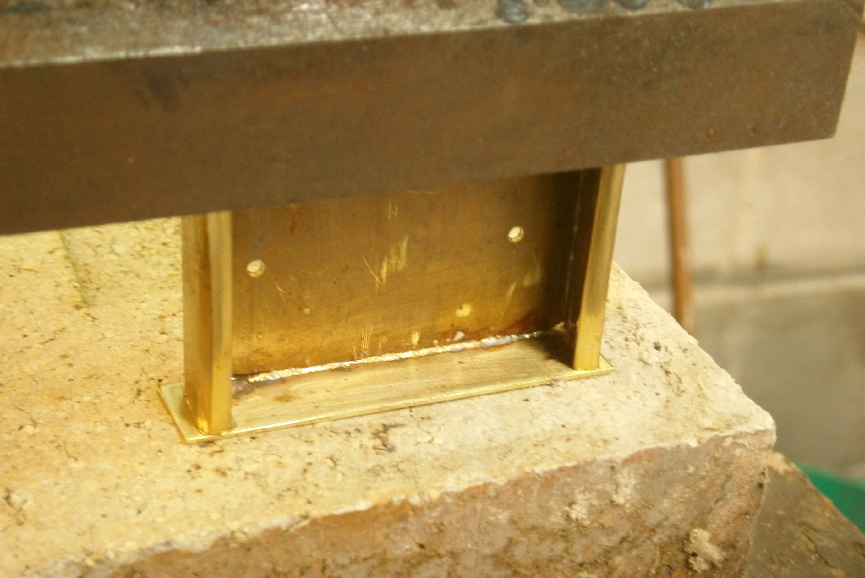
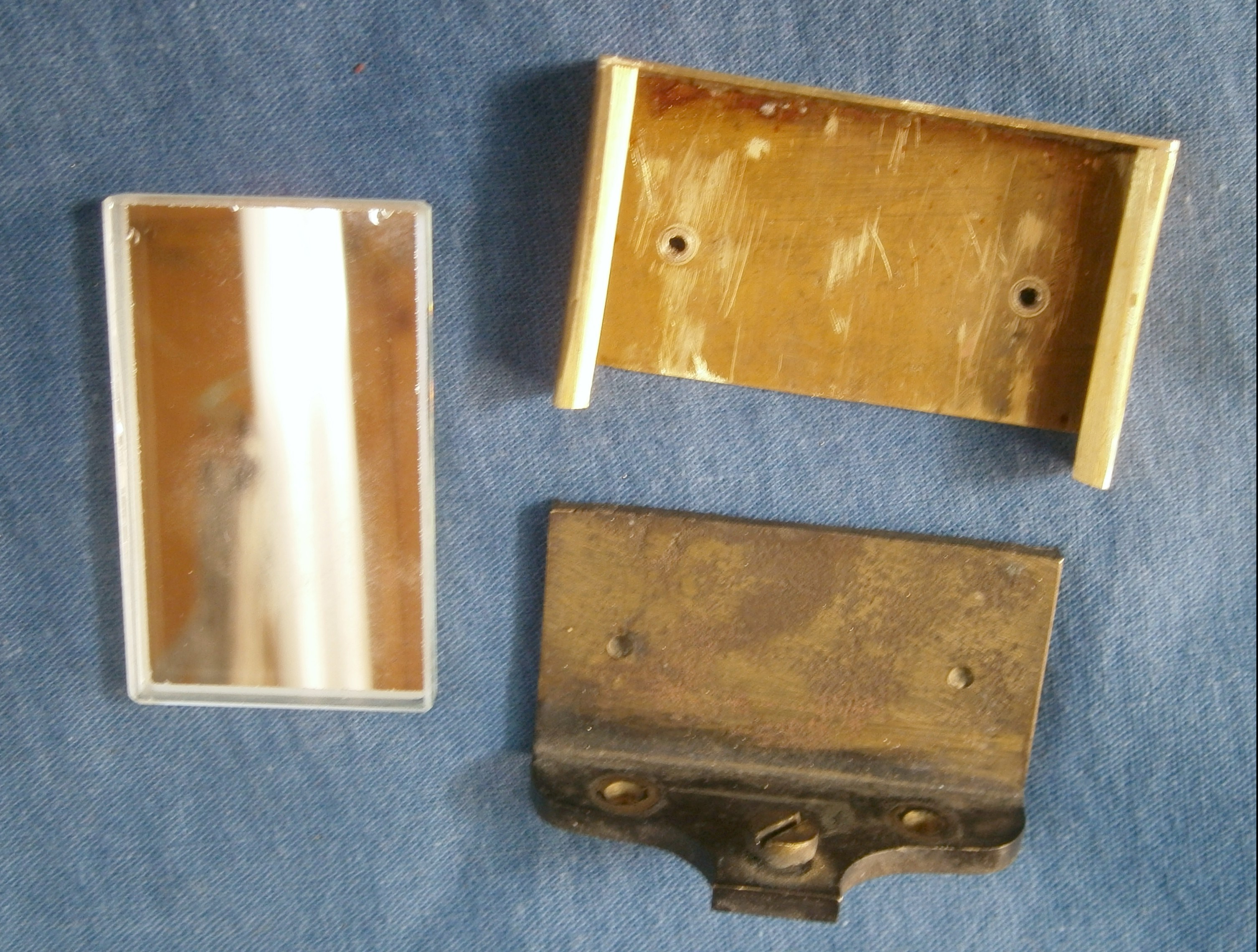
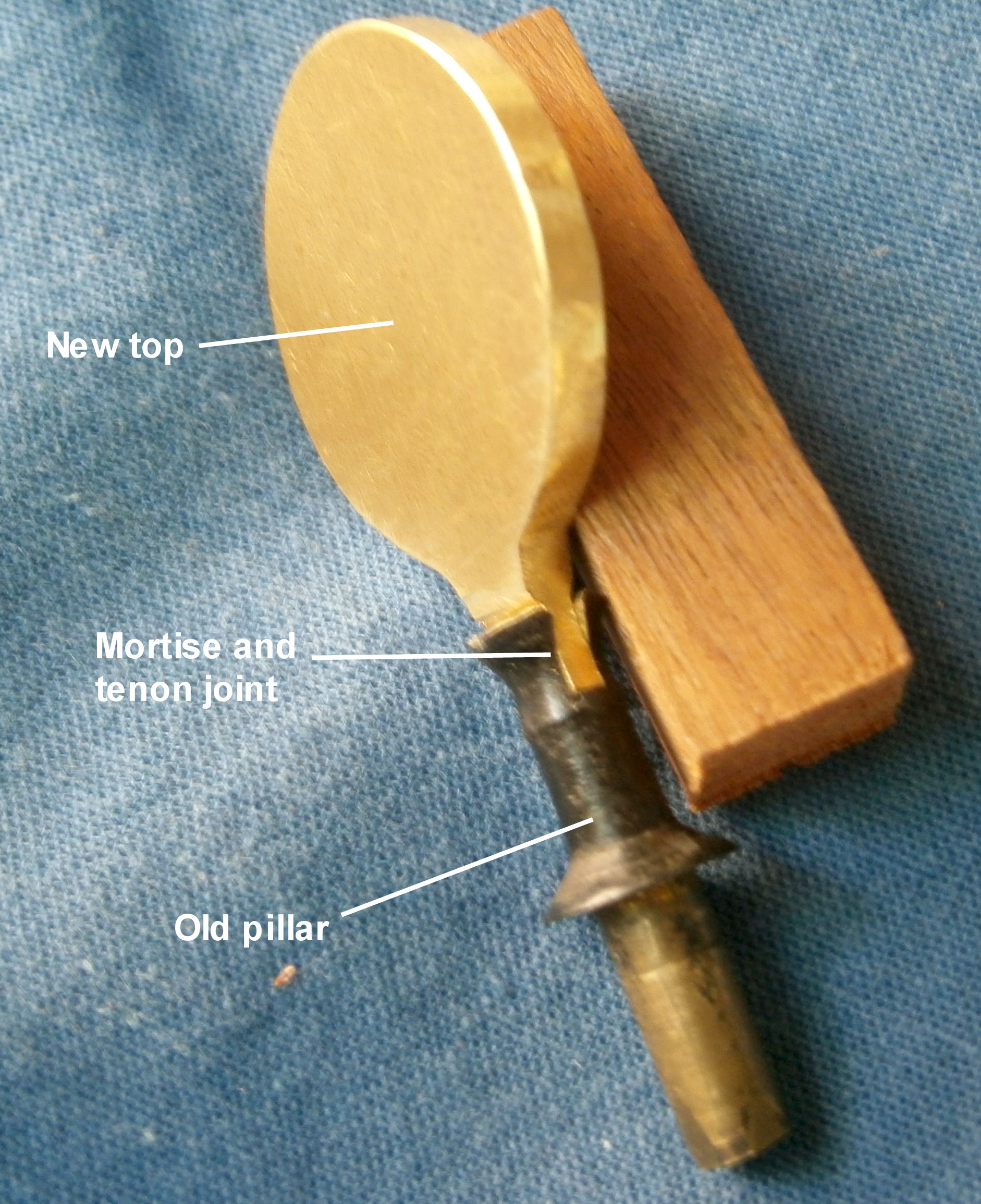
Figure 5 shows the end of the shaft of the rotating base. It is connected via a square on the end of the shaft to a sector that has a half-nut on its end which engages with a worm inside a fabricated brass box. The sector is retained on the shaft by a screw with a large head(not shown). The worm box is attached to the frame by means of two screws which engage with two threaded brass bushes let into the frame. The sector can be locked in place by means of a clamp screw. Rotating the squared end of the worm shaft in turn rotates the rotating base and allows fine adjustment of the index error. Figure 6 shows the assembly exploded.

Figure 5: Means of correcting index error.
Figure 6: Index error adjustment exploded.

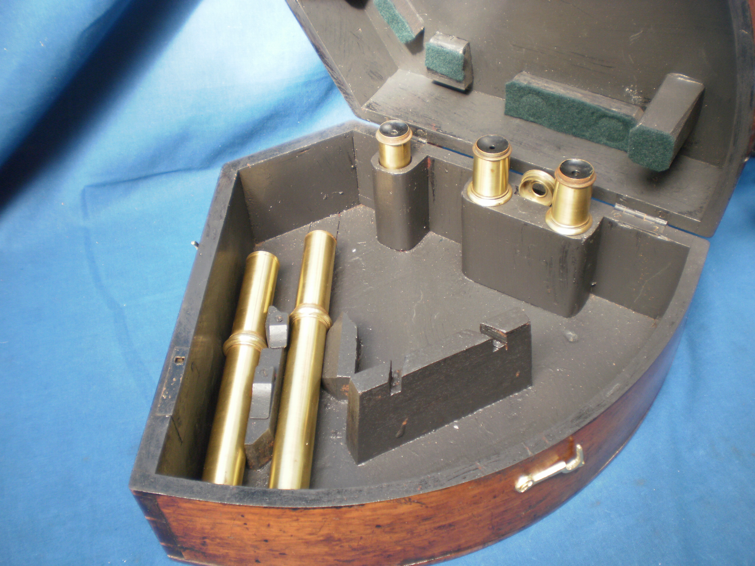
In the box of possible spare parts was a sighting tube. Happily, the thread on its body was of a larger outside diameter and of a different pitch to the internal diameter of the existing telescope rising piece, so I was able to turn it down and cut a new matching internal thread. I was able to ascertain the pitch of the latter by pressing a piece of Plasticene into the thread, removing it and then using an engineering microscope to measure the impressed thread.

Figure 7: Telescope mounting

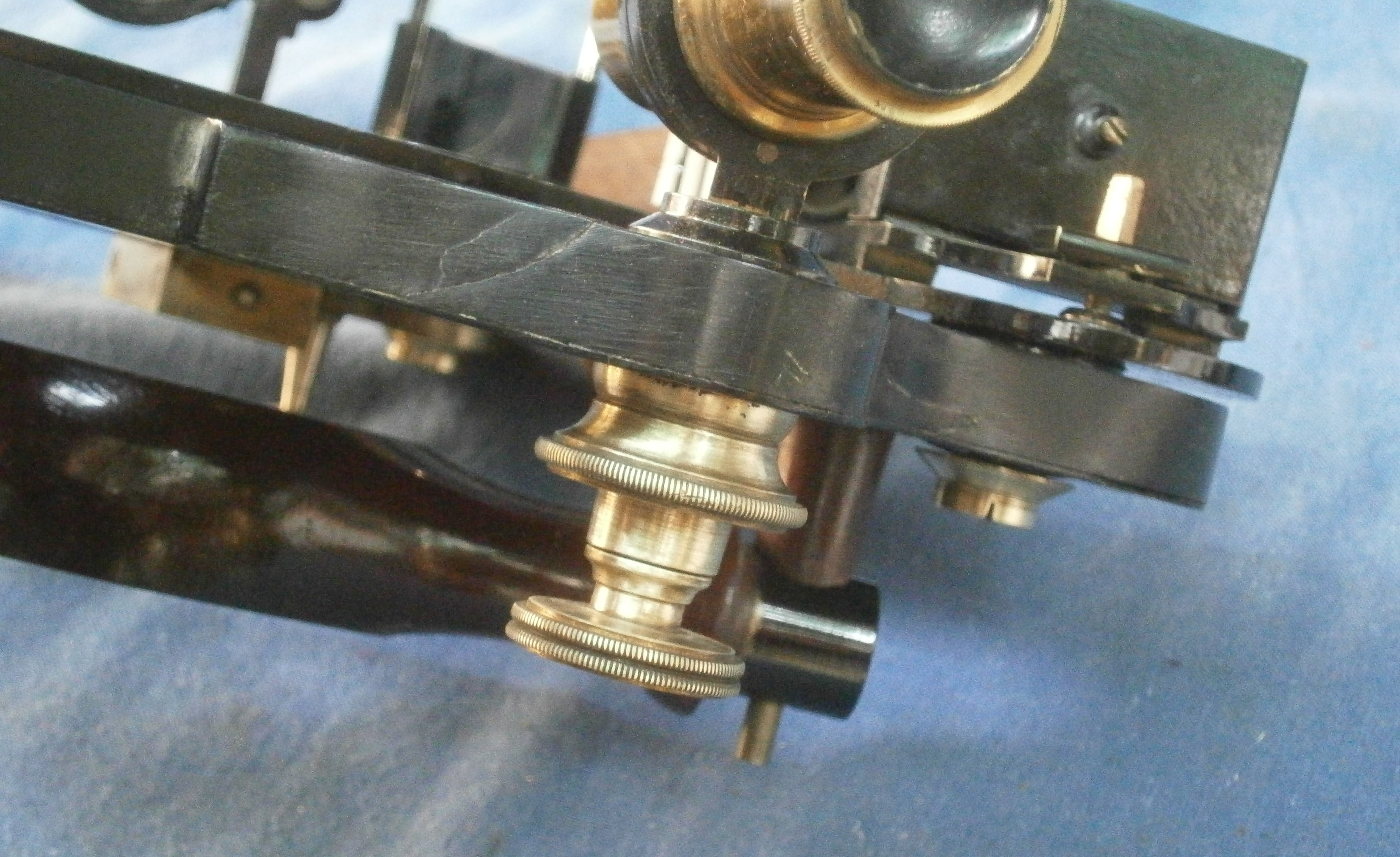
Figure 7 shows the telescope mounting. Avid readers of this blog will have noticed the similarity of the mounting to that shown in Figure 1 of my post of October, 2021, on a reflecting circle. This does not necessarily mean that the two instruments were contemporary, but rather that apprentices would copy masters, sometimes over several generations, or specialist makers of small parts would supply to “makers”, who were assemblers and finishers, rather like modern automobile manufacturers.

Figure 8 shows the mounting exploded. A large knurled nut holds a bush securely in the frame and the triangular stem of the rising piece slides in a triangular hole in the bush. A screw is held captive in the bush by means of a knurled thimble which has a square hole in it to match the square on the end of the screw. A countersunk screw(not shown) passes through the thimble into the end of the adjusting screw and tightening it secures the adjusting screw in the bush, allowing free rotation without up and down movement.

Figure 8: Telescope mounting exploded.
Figure 9: Tangent screw.

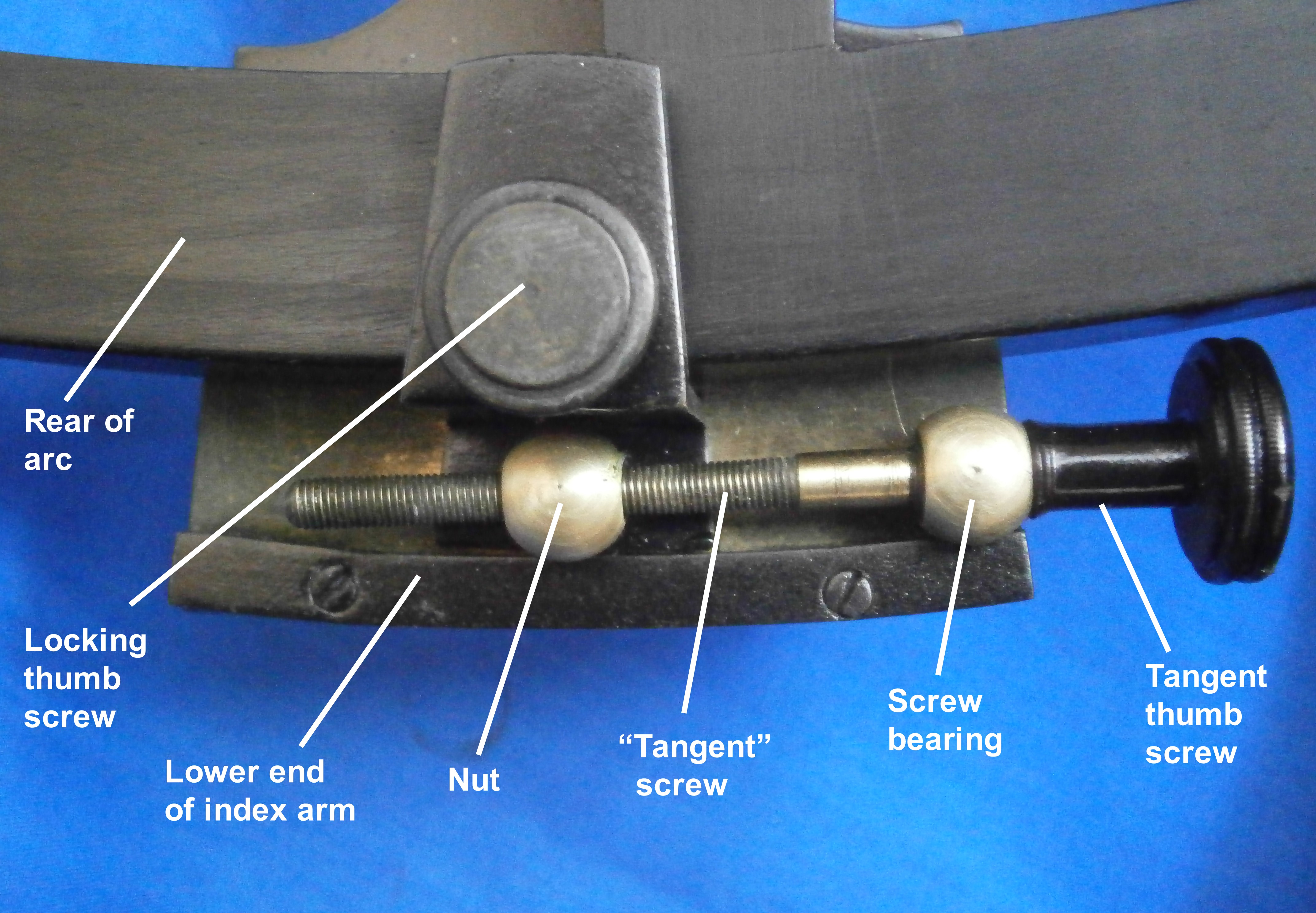
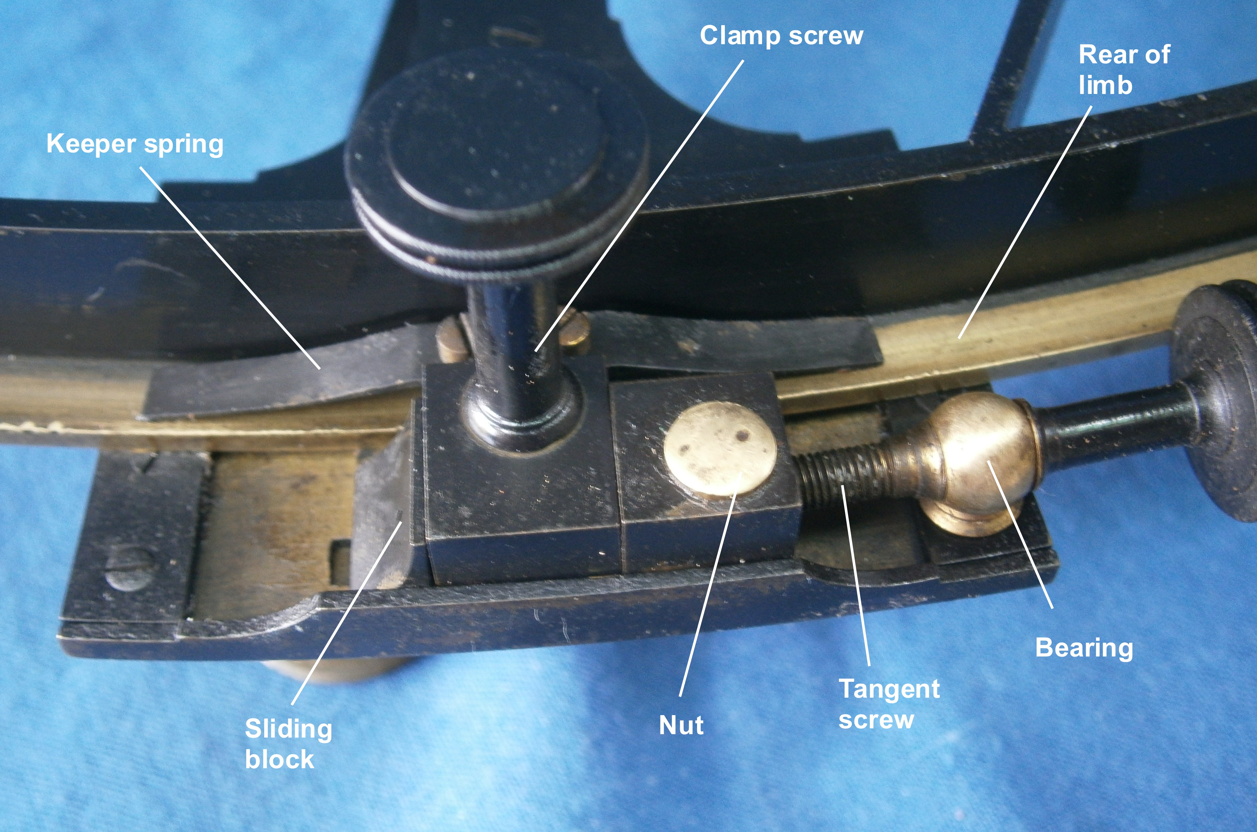
Reference to Figures 1 and 2 shows that the tangent screw with its nut and bearing were entirely missing, the sliding block was present and a mangled leaf spring remained. With the parts available, I was not able accurately to reproduce what was present before, but Figure 8 shows a closely similar appearance, the main difference being that the bearing was secured by means of a screw passing from the front of the index arm into its base. The original bearing was probably spherical and held in a spherical seat.

When the lock screw is tightened, the sliding block is locked to the limb and when the tangent screw is rotated the index arm slides over the block. When the lock is loosened, the index arm can be slid rapidly along the limb, while the leaf spring holds the arm in contact with the frame. The original spring and the little block that held it were too badly mangled to use and I had to make new ones. I resisted the temptation to use a piece of clock spring or a scrap of beryllium copper, and instead hammered a strip of brass to work harden it and make it springy as a contemporary artisan would have done. The resulting distortions had to be corrected by filing.

In the upper left of Figure 7 can be seen the way the index mirror is brought perpendicular to the plane of the arc. An adjusting screw with a square head is held captive in a tongue projecting from the index mirror bracket by means of a bar and two screws. There are two screws through feet securing the front of the bracket and their soles are slightly rounded to allow rocking as the adjusting screw is rotated in a threaded bush let into the top of the index arm. Peter Dollands invention, mentioned above, made these little complexities redundant. A mirror clip from the box of spare parts was easily modified with a file to fit the bracket.

There were three rather battered horizon shades in the box of parts and it was the work of a few minutes to make a shouldered screw and three washers to fit them into the existing bracket. I domed a further thin washer by placing it on the end grain of a scrap of wood, sitting a ball bearing in the hole and striking it hard with a hammer. This gave me a thin and stiff spring to adjust the friction when the screw was tightened. This type of spring washer is now known as a Belleville washer, patented in 1867 by Julien Belleville of Dunkirk. Fairly obviously, the principle was well known before that. A lock nut at the end of the screw then completed the assembly.

Figure 10: Horizon shades.

The index arm bearing followed the pattern shown in Figures 25 and 26 of my post for 11 March 2012 and it required only cleaning and greasing.

I used black laquer on brass surfaces, leaving screw heads bright as seems to have been the custom, and used black shoe polish to brighten the frame to complete the restoration.

Figure 10: Completed front view.
Figure 11: Completed rear view

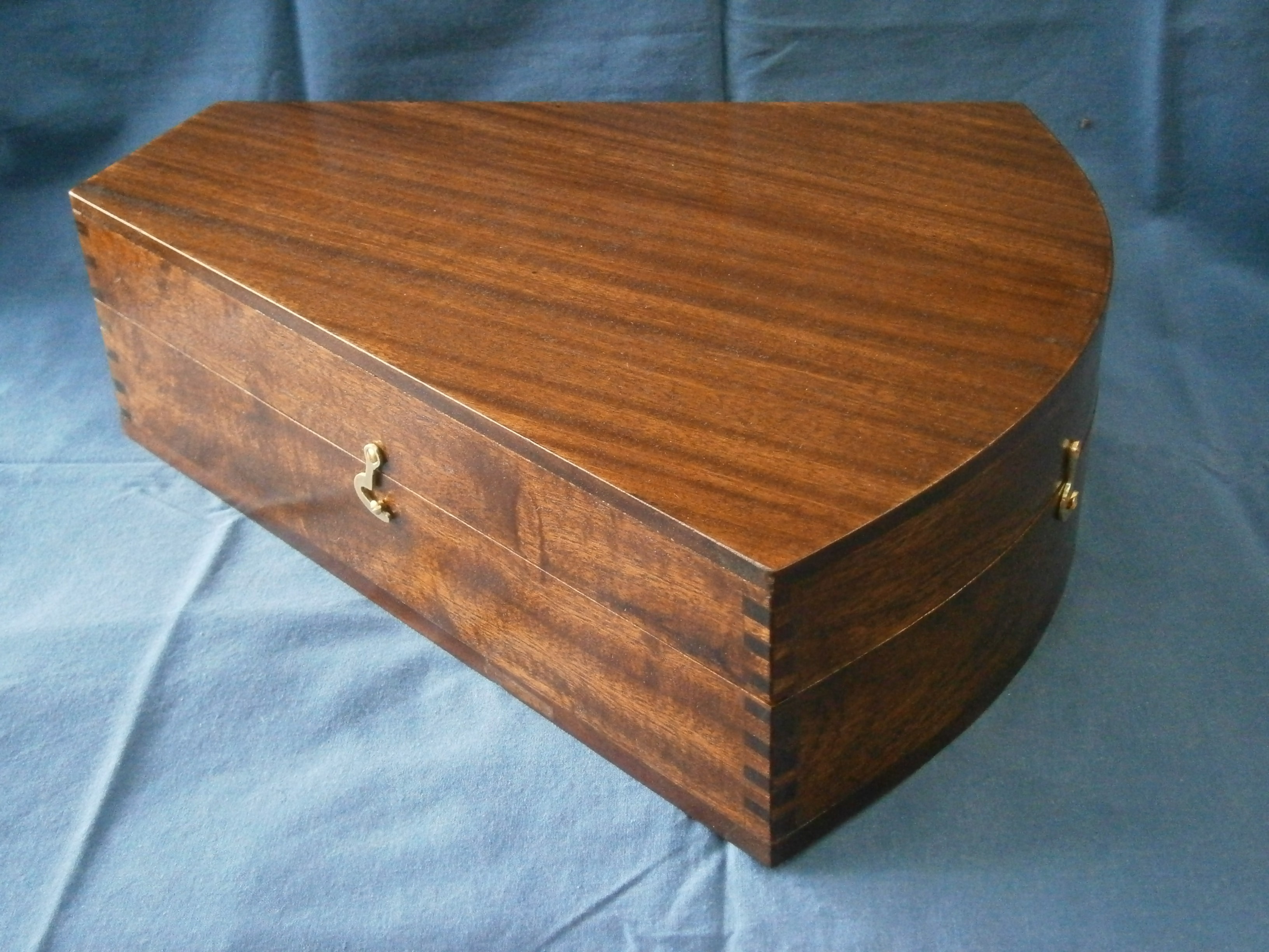
The finished restoration is shown in Figures 10 and 11.

Postscript Murray Peake has kindly provided me with some details of the maker, Louis Félix Védy, 1811 – 1875. He was active in the middle of the nineteenth century and was a principle supplier to the Dépot de la Marine. He was made a Chevalier de la Legion d’Honneur in 1851. His apprentice master was Antoine-Francois Jecker, 1765 – 1834, who worked for six years under Jesse Ramsden.


A Small Ramsden Sextant

14 10 2021

On page 64 of Peter Iflands Taking the Stars is a figure showing a small sextant bearing Jesse Ramsden’s name. According to Ifland, this was one of the last sextants made by Ramsden, though by the time of his death he had many workmen and it is unlikely that he made the instrument personally. Part of a batch of instruments sent to me by a friend in Australia for restoration was an identical instrument named W Harris 47 Holborn London. Harris was active from 1816 to 1839, though he almost certainly did not make the sextant bearing his name. It was common practice for retailers to put their own names on sextants, clock, chronometers and the like that had been made by others. Figure 1 shows the sextant in the condition that it reached me and Figure 2 shows the naming.

Figure 1: Sextant as received
Figure 2: Name.

Apart from the obvious dirt and perished shellac, the scale magnifier, horizon mirror clip and mirror, handle and sundry screws were broken or missing, while the tangent screw adjustment was seized. I followed my usual practice of reducing the instrument to its individual parts for a thorough clean in soapy ammonia solution followed by removal of all the decayed shellac and broken screws.

My friend had sent me a box of optical parts which included an Ramsden-type magnifier from a small theodolite complete with threaded barrel, so that my task was to saw out the arm from 3mm brass sheet, file it to final shape and cut an interior thread in the lathe to accept the barrel. Unfortunately, the square on top of the pillar had corroded away, but as the instrument was only to be displayed in future, I simply attached the arm with a screw (Figure 3).

Figure 3: New magnifier arm.

I made the missing horizon mirror clip by folding and soldering thin brass sheet, making and soldering in place a threaded boss for the retaining screw. The clip is visible in several of the figures that follow, including Figure 4 which shows the restoration largely complete.

Figure 4: Restoration nearly complete.

The index arm bearing is the conventional tapered brass journal in a bronze bearing that Ramsden made much use of in all his instruments and it is possible that he originated the practice. The bearing had become detached from the frame and was much battered, so I had to turn down the outside from its rough cast and bruised state. As there were no screws and it was impossible to determine the pitch of the old ones, as there was no standardisation of screws until the mid-1800s, I had to re-tap the holes to a BA standard and make new screws to fit (Figure 5). A threaded cap covers the end of the bearing and also acts as a leg.

Figure 5: Rear view of restored instrument.

The most striking feature of this little instrument is that the scales are both bevelled so both lie in the same plane, making for easy reading as both have the same contrast. Less obvious is that the scales are read from the centre of the instrument, rather than from the edge of the limb (Figure 6).

Figure 6: Scales and Tangent screw details

The arrangement for the tangent screw is rather unusual The screw is held captive in a bearing which is attached to the clamp, the underside of which may be seen in Figure 5 above. A curved tongue extends from the clamp and fits closely in a groove machined in the lower end of the index arm. The base of the nut retains it in place. The nut is attached to the index arm so that when the clamp is operated and the screw turns, the index arm is rotated and slides smoothly along the stationary tongue.

No provision is made to adjust perpendicularity of the index mirror, rather, it was made correct in the first place, a practice followed by only a minority of late nineteenth and twentieth century sextants. However, there is provision to make the horizon mirror parallel to the index mirror to adjust out side error, and to rotate the horizon mirror to adjust out index error (Figure 7).

Figure 7: Horizon mirror adjustments.

There was a wide variety of methods to adjust the horizon mirror, lasting even into the 1940’s with the perverse methods used in the US Navy’s Mark II sextant (described in my post of 30 November 2010). However, Peter Dolland took out a patent number 1017 in May 1772 for “Adjusting and improving the glasses of Hadley’s quadrants and sextant…”. In a letter to Neville Maskelyne (Phil.Trans. 1772 62, 95-98) he described the method which has been used for the large majority of sextants for most of the last century and a half, that of three screws bearing on the back of the mirror and opposed by three springs at the front.

Nevertheless in the late eighteenth and most of the nineteenth century, sextants used a variety of complex and ingenious ways to accomplish the same thing. Figure 7 above shows the approach taken with this little sextant. The horizon mirror is held against three pips on a bracket by a clip and a screw bearing on the back of the bracket. The bracket is mounted on a base which has two pips on its underside more or less at right angles to the telescope axis and the base is rocked with these pips as an axis by means of two screws, the rear one of which pulls from below by means of a knurled screw while the other one pulls from above by means of a slotted cheese head screw. It seems that there may have at one stage been a spring involved that allowed just the use of the front screw, but I was unable from the remains to work out how this was arranged.

This tilting base is attached by the screws to a rotating base and a slot is machined in the face of the frame to accommodate a tongue that ends beneath a rectangular hole in the rear of the frame. A cover extends from the rotating base to cover the roof of the slot (Figure 7) while another cover is provided to cover the hole in the rear (Figure 8). The tongue can be moved back and forth against a stout helical spring by means of a screw that passes through a threaded boss, thus rotating the mirror to adjust out index error. The foot of the boss is retained in the frame by two retaining pins.

Figure 8: Index error adjustment detail.

All that remains is to note that the arrangement of the four index shades is conventional, while the three horizon shades are neatly fitted in as shown in Figure 7 above. The shades fit over a pillar and are held in place by a squared washer and a cheese-headed screw. The squared washer prevent rotation forces from being transmitted from the shades to the screw, so that latter can be used to adjust the friction without risk of it undoing.

I have two more sextants to describe from the current batch of restorations as family and other commitments decide and hope that you have enjoyed your reading so far. If there is any specific topic you would like me to cover, please let me know at nzengineernz@gmail.com (I have no formal engineering qualifications, but during my clock-building years, someone called me a time engineer…).


A Late C18 Wooden Quadrant Restored

18 01 2020

Previous posts in this category include: “A C18 sextant named J Watkins”, “An Old Wooden Quadrant Restored”, ” A turn-of-the-century French sextant”, “A Half-size Sextant by Lefebvre-Poulin”, ” A Fine Sextant by Spencer, Browning and Co”,  “A C19 Sextant Restoration” , “Making a Keystone Sextant Case” , “Restoring a C. Plath Drei Kreis Sextant” , “Heath Curve-bar sextant compared with Plath” , “A Drowned Husun Three Circle Sextant”, ”Troughton and Simms Surveying Sextant” , “A Sextant 210 Years On” , “A fine sextant by Filotecnica Salmoiraghi”, “A British Admiralty Vernier Sextant”, “An Hungarian Sextant via Bulgaria” ,  “A Half-size Sextant by Hughes and Son” and “A Fine C Plath Vernier Sextant”, “Heath and Co’s Best Vernier Sextant.” and “An Early C19 Ebony Quadrant Restored”.

Two thousand and nineteen was a busy year for me and now that 2020 is upon us I find that I have not written a post in this blog for about a year, though not for want of trying, as I see that I got as far as writing the title of this one in August, 2019, having bought the instrument in April. My chronometer blog (www.chronometerbook.com) fared a little better, with one post. I have begun to make a catalogue of my nautical sextants and related instruments, and this morning found that I had omitted to describe a survey sextant that I acquired in 2013, so I will try to write about that after this one, in between mending and rating chronometers.

1 Case exterior

Figure 1) Case exterior.

All the photographs are of the instrument after restoration. For some reason, I did not think to take photographs as I proceeded. Except for a small area of the case at the bottom right and a re-positioned hinge, the case was intact. The stepped case looks rather archaic and I have come to associate it with early American instruments, or rather, instruments sold in America. If any one knows something different, I would be glad to hear of it. Where it is un-stained, the timber is light brown, but I am inclined to doubt that it is mahogany. Again, American readers may be able to inform me.

The octant came to me missing two of its legs and its peep sight. Fortunately, I could copy the remaining leg, and for the peep sight I had a model of the pillar that I could copy from a restoration described in my post of 13 June, 2018.

2 Label

Figure 2: Seller’s label.

A seller (there may have been others) was “Robert King of 219 Front Street, New York.  Between Beekman Street and Peck Slip.” The hand-written address is pasted on top of the rest of the label. All these names still exist, but unless 219 was down an alley way, it has been replaced by a modern-looking frontage. Perhaps someone in New York can add information that it not available by my having looked on Google Earth. I have not been able to discover when Robert King was active as it is unfortunately a very common name. Very many instrument makers did not actually make the instruments that they sold and this applies particularly to sextants,  because of the requirement for a large and expensive dividing engine. It may be that they sometimes assembled instrument from major parts and possessed enough skill to carry out overhauls and repairs. (See end note).

OLYMPUS DIGITAL CAMERA

Figure 3: Divider’s logo.

We can be sure that King did not make the frame of this instrument and it is very unlikely that he made any other parts. Figure 3 shows the central part of the arc, which has a very clear fouled anchor logo. This is usually associated with instruments divided by Jesse Ramsden after completing his second dividing engine in about 1774, with the logo flanked by the initial letters I and R. It may be that Matthew Berge, who took over the business after Ramsden’s death in 1800, continued to use the logo as a sign of excellence, though without the initials. Berge’s price list for 1801 shows him selling “Hadley’s Octants in ebony with ivory arches” for between £2  5s (£2.25) and £5  5s (£5.25). Families of the time could get by on about £40 a year and be comfortable on £100, so even a cheap ebony octant represented a considerable investment.

However, King may have carried out a repair on the octant as shown in Figure 4.  An area of weakness where the index shades are mounted could have led to splitting of the ebony frame along the grain. This area has been reinforced by letting in a slip of brass, secured at one end by a screw.

Repair 002

Figure 4: Repair to frame.

Early quadrants, which were divided by hand, necessarily had to have large radii, of about 380 mm (15 ins), and they were not provided with a handle. My quadrant has a radius of about 290 mm (11.5 ins) and has no handle, so while the design is archaic, it must have been made in the 1770s or later. Another ebony quadrant that I have is of about 250 mm (9.8 ins) radius and has a typical handle, so is probably later.

Figure 5 shows the octant in its case with the major parts labelled for the benefit of those people who have yet to buy a copy of “The Nautical Sextant.”

3 GA front in situ

Figure 5: Octant in its case

As is usual with keystone cases, the octant is a tight fit and the curved part of  the case is not, as one might expect, a segment of a circle, but its radius increases from left to right, so  the index arm has to be set over to the right. I have added pieces of felt at each corner to the rectangle of cork that prevents the index arm expansion from resting against the inside of the case.

15 Case interior

Figure 6: Interior of case.

Just visible in Figure 6 is a circular piece of cork, faced with felt, attached to the lid. This sits on top of the transverse member of the frame and, with a pocket for the top leg which I have added, prevents the octant moving about when the lid is closed.

Figure 6 shows a rear view of the instrument out of its case. The frame is made of heart ebony, a hard, black, stable and very dense African hardwood. The index arm and most of the other fittings are of brass, while the arc and note pad are of ivory.

4 GA rear

Figure 7: Rear (right hand side) view.

Figure 8 shows details of the scales. The main scale is divided to 20 arc-minutes and the vernier allows readings to a precision of 1 minute. The scales are very well preserved. Ivory tends to shrink in a dry atmosphere and often the glue that holds the main scale inlaid into the limb gives way at one end. The vernier is as usual riveted to the index arm and shrinkage often causes the ivory to crack around one of the holes.

5 Scales

Figure 8: Details of scales.

When wooden frames gave way to ones of bronze, ivory for the scales continued to be used in cheap instruments, rather than scribing  divisions directly into a brass limb rivetted to the frame. The sextant described in my post for September 17, 2018  is the only one I have seen where this has been done. Usually, an arc of silver was let into the limb, as the pure silver was unlikely to divert the scriber like the hard spots often found in the brass of the era.

8 Tangent screw detail

Figure 9: Tangent screw details.

The mechanism for fine adjustment of the index arm is shown in Figure 9. Releasing the “clamp” by unscrewing the locking thumb screw allows the index arm to move freely so that a body can rapidly be brought down to near the horizon. Then the Z-shaped piece of metal shown here and in Figure 10 is clamped to the limb. The nut is also attached to this piece of metal or “clamp”. The tangent screw is held captive in its bearing on the right of Figure 9 and the bearing is attached to the index arm, so that when the screw is rotated the index arm is moved slowly one way or the other about a curved guide formed for the base of the clamp on the back of the index arm.

Tangent end view 002

Figure 10: End view of tangent screw clamp.

A piece of spring steel protects the back of the limb from the tip of the clamp screw. What is difficult to show in either photo is that there is a short tongue projecting at the base of the “Z” and this slides in a rebate on the front of the limb – except when the clamp screw is tightened.

As the peep sight was missing altogether, I had to use the pillar from another sextant as a guide to its shape, and then saw and file up the shape of the disc part from sheet brass.  I then inserted the disc into a mortice machined into the top of the pillar and secured it with solder.

6 Peep sight eye side

Figure 11: Peep sight from eye side.

The centre line of the two holes lines up with the horizontal centre line of the horizon mirror. The hole nearer the frame lines up with the junction of the plain and silvered parts of the mirror, while the other hole allows a larger view of the horizon for when its contrast is poor. The shade shown in Figure 12 can be rotated to obscure one or the other of the holes.

7 Peep sight

Figure 12: Rear of peep sight.

Flint glass was essential to make achromatic lenses, but in the eighteenth century it was difficult to obtain in large pieces, so that telescopes were not only expensive but had relatively small apertures of 16 to 20 mm.

When a sextant or octant was used only for taking the noon altitude of the sun for latitude, a peep sight was perfectly adequate for a “normal” eye, which could resolve an arc-minute, in keeping with the precision of the instrument. A normal eye is usually quoted as 6/6 vision (20/20 in the USA), but many young people have 6/4 vision or even better, meaning they can resolve detail at 6 metres that a “normal” has to be at 4 metres to resolve.

When it became necessary to resolve 10 arc seconds (one sixth of a minute) in order to measure lunar distances between the moon and the sun or stars, telescopes became nearly essential, though that great navigator, humanitarian and scientist, Captain James Cook, did not use one until  his second voyage of exploration. On January 15th, 1773, he wrote in his log “…we can certainly observe with greater accuracy with the telescope when the ship is sufficiently steady which however very seldom happens, so that most observations at sea are made without…”  With the wider field of view available with a good modern telescope it is easier to use one, but on my voyages aboard HMB Endeavour, which rolls a lot, I usually brought down a body without the telescope and then added the telescope to my modern sextant to make the fine adjustment and bring the body to sit accurately on the horizon.

Index bearing 002

Figure 13: Structure of index bearing.

Figure 13 shows the structure of the index bearing. Strictly speaking, it is that which encloses the journal or shaft, but loosely the word is used to include both. There is a brass washer let into each side of the frame and the two are held together by two rivets. The washers enclose a short piece of brass tubing, which forms a bearing for a plain parallel shaft attached to a large circular table on the front (left) side of the octant. This carries the index mirror. Originally, a piece of parchment separated the table from the frame. As it had fallen apart, I replaced it with a thin sheet of nylon.

On the back or right hand side a heavy brass washer with a a square hole fits closely over the square on the end of the shaft, so that it turns with the shaft without rotary motion being transmitted to the securing screw and loosening it. There is no provision for taking up wear, but as it is not an instrument of the highest precision and the shaft is lightly loaded and always moves slowly, no wear is to be expected. An old author (I forget which) made reference to what we would now call “stick-slip” or “stiction”  and suggested that having achieved contact of a body with the horizon and clamped the index arm, it  might continue to move a little without the tangent screw having been touched. I have never been able to observe this. It may be that the author had over-tightened the bearing.

With further development of octants and sextants, a tapered bearing was adopted almost universally, as it allowed for fine adjustment, though the narrow adjusting screw was prone to be over-tightened and broken off by heavy-handed mariners who did not understand the bearing’s structure.

Figure 14 shows the front of the index mirror and its bracket. The “silvering” was probably made from an amalgam of tin with mercury and it was coated with protective sealing wax. While I have replaced the very badly decayed horizon mirror, I have left the index mirror in place as it is still just about usable for demonstrations. The clip that holds it to its bracket is archaic as it applies pressure to three edges of the mirror. From the middle of the eighteenth century it had been appreciated by the Dollonds that to avoid straining and distortion of the glass, it should be restrained at three points only, and seated under these points on three nipples.

9a Index mirror front

Figure 14: Front of index mirror and bracket.

The rear of the clip (Figure 15) has two screws that pull the mirror clip backwards so the the edges of the mirror are held against narrow raised edges of the right angled bracket. The underside of the  base of the bracket is slightly curved so that it can be tilted slightly by the tilting screw so that the mirror can be brought to a right angle with the plane of the arc. This is an effective way of doing so, but if not properly understood, the thread of the tilting screw could be stripped or the base bent by a heavy-handed adjuster.

9 Index mirror rear

Figure 15: Rear of index mirror bracket.

The base of the index shades can be seen in Figure 3 at the top right. Figure 16 shows the shades and the base in detail.

16 Shades

Figure 16: Index shades.

The glass of a shads was usually held in its frame by swaging or deforming the metal over the bevelled edge of the glass, and this can be seen in the bottom two shades. In the top one, the glass seems to have worked loose and is held by antique putty which I have left in place. The shades are separated by washers and held together in a fork which can be closed up by the screw so that they do not flop around. Note in passing that the slot in the screw is vee-shaped, having been formed by a file rather than by a saw, a reflection on the expense and difficulty in the era, of working steel to make a hack or rotary saw.

The split in the base to make a spring allows the shades to be removed easily, an archaic and unnecessary feature in this instrument and presumably a left-over from the time when octants were sometimes fitted with back sights which needed the shades to be moved in position, as in the one I described in my post of June 13, 2018. A brass facing was attached to the sextant by two screws, with a slot for the shades and holes for the horizon mirror base and its adjustment (Figure 5).

The horizon mirror has a complex arrangement for adjustment. The mirror is held by the clip against a bracket in the same way as for the index mirror. The bracket lies on top of a circular base which can be tilted about an axis of two short pins or nipples by means of two screws to remove side error (see Figure 19 for the details). The base has a short tapered shaft with a square formed on the end which passes through the frame and a straight crank, to be secured by a washer on the other side.

11 H mirror detail

Figure 17: Horizon mirror and bracket.

The base can be rotated through a small angle to remove index error  by means of a half-nut formed on the end of the crank and a worm screw, and locked in place by a locking screw (Figure 18). The exploded view in Figure 19 perhaps makes the arrangement clearer.

13 Horizon adjust

Figure 18: Horizon mirror index adjustment.

When I removed one of the tilting screws it lost its head and I was obliged to make a new one. The old and the new can be seen in Figure 19, lying above the rotating base.

14 Horizon adj exploded

Figure 19: Horizon mirror adjustments exploded.

I have not illustrated an important addition to the octant, the handle,  because none was provided. It is likely that this was a basic octant without frills.

You can find many details about the structure of sextants up to modern times in my book “The Nautical Sextant.” available through Amazon and good nautical booksellers like Paradise Cay and Celestaire.

End Note: Murray Peake has been much more patient than I have in tracking down some details of Robert King:

A Thaxter compass in the National Museum of American History has a seller’s card by Robert King whose dates are given as ca. 1769 to 1868, “…an instrument maker from England who spent most of his career in New York City.”

An auction site also lists an octant with King’s label. This is 17 inches in radius, made of mahogany, except for the lower end of the index arm and is fitted with a back sight. It is a very early octant and was probably divided by hand by a specialist in the art.

Robert King appears in Longworth’s New York Register and City Directory for 1812 and 1817, living in Elm Street. By 1827 he is in Lombard Street and left there in about 1833 for 18 Monroe Street. He appears for the first time in Front Street in 1837/38, but at 212, not 219. By 1845/46 he is accompanied by R King Jnr and by 1850 he is no longer listed.

Presumably, King knew his own address. Perhaps 212 was his residence and 219 his workshop or vice-versa?


A C18 sextant named J. Watkins

17 09 2018

Previous posts in this category include: “An Old Wooden Quadrant Restored”, ” A turn-of-the-century French sextant”, “A Half-size Sextant by Lefebvre-Poulin”, ” A Fine Sextant by Spencer, Browning and Co”,  “A C19 Sextant Restoration” , “Making a Keystone Sextant Case” , “Restoring a C. Plath Drei Kreis Sextant” , “Heath Curve-bar sextant compared with Plath” , “A Drowned Husun Three Circle Sextant”, ”Troughton and Simms Surveying Sextant” , “A Sextant 210 Years On” , “A fine sextant by Filotecnica Salmoiraghi”, “A British Admiralty Vernier Sextant”, “An Hungarian Sextant via Bulgaria” ,  “A Half-size Sextant by Hughes and Son” and “A Fine C Plath Vernier Sextant”, “Heath and Co’s Best Vernier Sextant.” and “An Early C19 Ebony Quadrant Restored”.

A few months ago I acquired an old sextant for a very modest price, as it was without telescopes or case. Restoration was straight forward, as all the parts were present. It was only necessary to clean and re-lacquer  parts and polish screw heads and then find a new home for the instrument. Figures 1 and 2 show the general arrangement of the restored sextant from the front and back, and I have labelled the main parts for those who have not yet had the wisdom to buy “The Nautical Sextant”.

Figure 1: The sextant and its parts.


GA rear better

Figure 2: Rear view of sextant.

I show the naked frame in Figure 3. It is slender by modern standards, but seems to be rigid enough for its purpose.

Frame bare

Figure 3: The naked frame restored.

I believe that this is a relatively early sextant, based not only on the name engraved on the limb but on several other factors. To take the name first, it is “J Watkins Charing Cross London”.  This must refer to Jeremiah Watkins who succeeded his uncle, Francis Watkins (1758 – 1810) in 1784 at the age of about 26 years. I have been able to find only one other sextant with J Watkins’ name on it (sold in London in 2014) and I suspect that he was the retailer rather than the maker. It was common practice for sextants, chronometers, clocks and the like to be sold un-named, for the retailer to add his name. The main activity of Watkins senior and junior, and later Watkins and Hill, was in making telescopes with achromatic lenses.

Name

Figure 4: The name.

Looking closely at the name (Figure 4a ), the second “s” in “Charing Cross” is the old English long s, with a nub on the left of the descender. This form of s  had fallen into disuse in printing by 1800 and its use here suggests the engraver had trained well before 1800.

Long s

Figure 4a.

The brass limb was attached to the hard bronze frame by countersunk screws whose heads were then filed off flush, and the ghost of one of these screw heads can be seen above the “n” of Charing Cross. Rather unusually, the divisions are made directly into the brass rather than into a band of silver let into the brass, a practice established well before 1800. The usual explanation for this practice is that brass of the time contained hard spots which could have diverted the scriber of the dividing engine from its true path and that lines on brass tended to be ragged. However, this may have applied only to English brass, as makers preferred if they could to import high quality “Dutch” brass from near Aachen in Germany.

Scale divisions

Figure 5: Magnified view of scale divisions.

A close up view of the divisions (Figure 5) shows them to be perfectly regular, so that the scale was, I am sure,  machine divided. Jesse Ramsden’s first dividing engine was finished in about 1766 . It surpassed all previous attempts at accurate machine division, but he was not satisfied with it, and completed an improved version in June 1774. Around about this time he produced a sextant shown in Figure 6, with a frame very similar, if not identical to my Watkins’. By 1789 there were three dividing engines in London, By Jesse Ramsden, John Troughton and John Stancliffe, and by 1808 there were perhaps a dozen.

Copy of Ramsden sextant

Figure 6: Sextant by Jesse Ramsden.

This suggests to me that the two sextant frames had a common source in a specialist foundry and we know that Ramsden used specialist  founders when he needed castings. The finish is very regular and there is no signs that it was sand cast. More likely is that it was cast in bell metal (a bronze high in tin) by the lost wax method.

The radius of the arc is nine inches (229 mm) and by 1800, because it had by then become possible to divide small radii more accurately, the more usual radius was around six and a half inches (165 mm). Thus, these several features lead me to suppose that the sextant was made some time after 1774 and before 1800.

The telescope ring and rising piece are of a form that remained common well into the twentieth century. The telescope is held in a ring that can be adjusted so that the axis of the telescope is parallel to the frame, while the whole can be raised or lowered on its square rising piece by means of an internal captive screw and knurled knob (Figure 7).

Telescope rising

Figure 7: Telescope ring.

Compared to later sextants the index mirror is unusual in that there is no provision made for adjusting it to be at right angles to the plane of the arc. In some sextants of this era, of the three large screws seen in Figure 8, only the two outer ones attached the bracket to the index arm, while the central screw was threaded into the bracket and its tip bore on the face of the index arm, so that it was possible to rock the bracket a little to adjust it. In this sextant, the bracket was simply made square in the first place.

Index rear

Figure 8: Index mirror bracket.

Figure 9 shows the front of the bracket and two of the three nubs or nipples on its face, against which the mirror was held by a clip with three tongues opposite the nubs. When the small central screw seen in Figure 8 is tightened, the mirror is held strain-free to the bracket by the clip.

Index structure

Figure 9: Index mirror clip and bracket.

The index arm bearing is shown in Figure 10.  It is of the form used by almost every maker until late in the twentieth century. The index mirror is attached to a disc to the underside of which is attached a tapered journal which runs in a corresponding hole in the index arm bearing. The fit is adjusted by means of an axial screw via a washer.  The washer has a square hole in it that fits over a square on the end of the journal. This prevents turning forces from being applied to the screw and loosening or tightening it.

In this sextant, the whole is enclosed in a cover, which also doubles as one of the feet of the instrument. Many makers copied this practice, though in the twentieth century, when two World Wars required quantity production, it was often omitted.

OLYMPUS DIGITAL CAMERA

Figure 10:  Index arm bearing.

The method of adjusting the position of the index arm is shown in Figure 11 and is typical of the practice used in practically all vernier sextants until the last were produced in the late 1930s. A block is able to slide in a guide fabricated on the rear of the index arm expansion and the block carries a bronze nut, which sometimes has an adjustable split in it to ensure a close fit upon the tangent screw. Running in the nut is the steel tangent screw, held captive in its bearing which is attached to the index arm. Rotating the screw can move the block in its slide, but in practice, once the position of the arm has been roughly set by sliding the index arm by hand, the clamp screw clamps the sliding block to the limb of the sextant. Then, when the screw is turned, it is the index arm that slides on the block.

Tangent screw

Figure 11: Tangent screw.

Figures 12 and 13 show the methods for adjusting the horizon mirror. The mirror bracket sits atop two circular tables. The top one may be tilted against a concealed spring using the adjusting screw, shown in Figure 13, to correct for side error.

Index adjust front

Figure 12: Horizon mirror adjustment, side view.

The bottom circular table may be rotated through a small angle to correct for index error, using two capstan headed screws that lock against each other. The screws bear on a tongue which is an extension of the frame and the table rotates about an axis which passes through the frame and is secured by the large screw underneath.

Index adjust rear

Figure 13: Horizon mirror adjustment, rear view.

This rather complex arrangement is used on several sextants of this era. The sextant described in my post of 10 November 2009 shows an identical system, while another , shown in the post of 10 June, 2010, has a different though equally complex system. Before long, the much simpler method came in, of screws bearing against the back of the mirror with springs opposing the movement against the front of the mirror. However, some makers persisted with unreasonably complex systems of adjusting the horizon mirror well in to the twentieth century. Brandis was one late C19 maker whose system was copied for the US Navy Mark II sextant of the 1940’s and I have illustrated it in Figure 9 of my post of 30 November 2010.

Like many sextants that I can afford to buy, this instrument lacked a case. For the last nine years, I had been hoarding a case that had housed a pillar sextant. Usually, sextant cases are of mahogany, not brass-bound rosewood, indeed, this is the only example I have ever seen for a proper sextant, rather than the decorative so-called  reproduction ones from the Indian sub-continent. Figure 14 shows how I have adapted the case for my Watkins sextant. Originally, it would probably have lived in a keystone case, which are difficult to make  and difficult to carry. I had two contemporary telescopes saved against the day when I would acquire an antique sextant without any and had only to do a little screw-cutting on the lathe for them to fit in the telescope ring.

Case 002

Figure 14: Sextant in new home.

This completes my one hundred and third blog post on sextants and, while I have material for two more, I will then have run out of subjects. I am open to suggestions  about further subjects. If you have a particularly interesting sextant I would be happy to consider a guest post, though I would reserve the right to edit it if necessary. If you are interested in things navigational, don’t forget to have a look at my other site: http://www.chronometerbook.com


An Old Wooden Quadrant Restored

13 06 2018

Previous posts in this category include: ” A turn-of-the-century French sextant”, “A Half-size Sextant by Lefebvre-Poulin”, ” A Fine Sextant by Spencer, Browning and Co”,  “A C19 Sextant Restoration” , “Making a Keystone Sextant Case” , “Restoring a C. Plath Drei Kreis Sextant” , “Heath Curve-bar sextant compared with Plath” , “A Drowned Husun Three Circle Sextant”, ”Troughton and Simms Surveying Sextant” , “A Sextant 210 Years On” , “A fine sextant by Filotecnica Salmoiraghi”, “A British Admiralty Vernier Sextant”, “An Hungarian Sextant via Bulgaria” ,  “A Half-size Sextant by Hughes and Son” and “A Fine C Plath Vernier Sextant”, “Heath and Co’s Best Vernier Sextant.” and “An Early C19 Ebony Quadrant Restored”.

A month or two ago, I acquired an ancient ebony-framed quadrant in a sorry state, with several important parts missing. Figure 1 shows the front view of the instrument as received and Figure 2 shows the back.

1 GA as found

Figure 1 : Front, as found.

2 GA rear as found

Figure 2 : Rear as found.

The pictures show clearly what was missing and damaged so I will not list them here, but instead digress to try to estimate the date of the instrument. Many ebony-framed octants were made and were often called “Hadley’s quadrant” or simply “a Hadley”. Most of them bear no maker’s name, though some of them, if divided by Ramsden, will bear evidence of this on the main scale. Hand-divided quadrants were of a large radius, 15 inches (380 mm) or more. The improvements due to Ramsden-type dividing engines allowed the radius to be reduced with no loss of accuracy, and most nineteenth century wooden instruments had a radius of about 9 inches (230 mm). The size of my new example lies somewhere between, at about 11½ inches (290 mm).  Early illustrations of quadrants in use often show it being held by the frame, as no handle was provided, and the absence of a handle or any trace of one ever having been present, leads me to believe that this quadrant is relatively early, but after the advent of machine dividing in around 1767 (the description of Ramsden’s second engine was published in 1777 but his first engine dates to perhaps ten years before this).

Two further archaic features are the presence of a back sight pinhole or pinule and the design of the mirror brackets. I will borrow the words of W E May in his “A History of Marine Navigation” (1973, ISBN 0 85429 143 1) to explain the back sight: By altering the angle of the horizon glass and moving the eyepiece to a position close to it on the same radius, the octant could be used  for what was called a ‘back observation’, when the horizon opposite to the object instead of below it was used. The angle measure was then the complement of the altitude….It is extremely doubtful whether the back observation was ever used in practice.”  The light rays reaching the secondary mirror and pinule from the index mirror pass through the clear part of the normal horizon glass before being reflected into the eye by the secondary mirror, while the horizon is viewed through a slot in the silvering of the latter (Figure 3).

16 Secondary mirror

Figure 3 : Mirror and pinule for back sight.

Although the index mirror bracket was absent, the other two mirror brackets allowed me to study the design. Two screws pass through threaded holes in the back of the bracket and bear upon the back of the upright of an angle bracket. The vertical edges of the bracket are folded over so that when the screws are tightened, they draw the mirror back against vertical ridges on the front of the upright.  Figure 4 shows the edges of the new index mirror bracket being folded over a steel pattern.

3 Folding index bracket

Figure 4: Edges of new index mirror bracket being formed.

If the ridges on the upright do not lie in the same plane, the mirror glass will be distorted and Peter Dollond pointed this out to Nevil Maskelyne, the Astronomer Royal, in a letter of February, 1772 and there is a reference to it in Phil. Trans. LXII, p291, 1772. Among other matters, he described the now modern practice of sitting the mirror against three points and with springs or lugs on the front of the bracket bearing on the mirror opposite these points. Figure 5 shows this practice had been adopted in a sextant made in about 1790.

3b Index mirror bracket 002

Figure 5 : Peter Dollond’s method of securing mirror.

Thus, I tentatively date the quadrant as being after 1767, but not much later, as Dollond’s method of securing mirrors seems to have been rapidly adopted.

To return to the construction of the new index mirror bracket, after folding the sides and forming the retaining folds on the edges of their front I soldered the top to the sides. Figure 6 shows this being done, with a weight used to hold everything in place while the solder froze.

5 solder bracket roof

Figure 6 : Soldering top of index bracket to back and sides.

The holes for the fixing screws can be seen and after filing the top to its final shape, I riveted two threaded bushes in place. Figure 7 shows an exploded view of the completed bracket with its angle plate, while Figure 8 shows the completed bracket and mirror in place.

6 bracket complete

Figure 7 : Index mirror and bracket, exploded view

3a Index mirror bracket 001

Figure 8 : Completed Index mirror bracket.

The next part to receive my attention was the pinules or pin hole sights. Actually, the holes are about 2 mm in diameter, rather larger than your usual pin…
All that remained to guide me was the base of one of them, so I laboriously cut out two discs of 3 mm brass sheet, filed them to shape and married one of them to the existing base by cutting a slot in it, applying solder and smoothing to shape with a file (Figure 9). I copied the base for the other sight. The standard sight has two holes in in, one in line with the silvered edge of the horizon glass and the other a few mm higher, so as to admit more light from the horizon to the eye when there is poor contrast between the sea and the sky. Even small increases in light intensity give worthwhile increases in contrast. I also fashioned a little cover (visible in Fig 11) that can be swung into place to cover one or other of the holes. The back sight has only one hole, aligned with the slot in the silvering of its mirror.

7 Pinule repair

Figure 9 : Pin hole sight repair.

If you compare Figure 3 with Figure 10, you will see that in the latter , there is a defect in the wood of the frame. I made this good with car body filler, stained black with grouting stain, and then sanded to shape and smoothness, followed by a few coats of French polish until it matched the finish of the surrounding wood.

4 frame damage

Figure 9 : Damaged frame (see also Fig 3)

The missing horizon shade glass was replaced by a disc of ruby red glass, which I cut out with a trephine. If you look carefully at Figure 1, you will see a rectangular slot just below the base of the horizon shade on the photograph. This is also visible on the back, and there is a further slot higher up which is occupied by the base of the horizon shades, so that the latter can be, as it were, unplugged and transferred to the lower slot, to provide shades when using the back sight.

Apart from a general clean-up and fitting a piece of Ivorine for the name plate, that completed repairs to the front. The most important item missing from the back was the washer and screw that secures the index arm bearing journal to the frame. Unfortunately, the screw had broken off and I had to drill it out and re-tap for a slightly larger size, but the washer presented no problems. The square hole in the washer has to fit closely over the square on the end of the bearing, as any tendency for it to turn might tend to loosen or tighten the screw and affect the adjustment of the tapered bearing.

It was a relatively simple matter to copy one of the legs and to make sundry new washers and screws. Two thumb screws lock the adjustments to the index and back sight mirrors and it was not too difficult to copy the remaining one. Happily, the threads seemed to be threads for which I have long-obsolete taps and dies, so I did not have to resort to the lathe to cut them. I have covered some of the details of the structure and adjustment of these parts here: https://sextantbook.com/?s=crichton

12 Details of new parts, back

Figure 10 : Details of replacement parts on back.

A piece of clock main spring, after some persuasion, provided the replacement for the broken spring that holds the index arm against the frame, leaving only a small piece of Ivorine to be let in, to replace the missing note pad.

On completely dismantling the instrument to clean the frame, I found a couple of minor cracks in the wood, which were easily closed up after infiltrating some glue with a fine blade and clamping. I cleaned the frame with a mild detergent and then gave it a coating of good quality furniture wax. Most of the brass parts would not have been left bright, so they received a coat of black lacquer. Figure 11 and 12 show the finished article.

14 Repairs complete front

Figure 11 : Front with finished parts before painting.

13 Repairs complete, rear

Figure 12: Rear before painting of replacement parts

The scales were in good condition apart from an incrustation of dirt which was easily cleaned with a little alcohol on a rag. Close inspection showed the ghost of some emblem, scarcely visible to the naked eye, between 45° and 50° (Figure 13).

15 Fouled anchor

Figure 13 : Ghost of Ramsden?

After careful cleaning with a fine point and playing with the lighting, a fouled anchor emerged under magnification, but, while this was an emblem used by Ramsden on ivory scales which he divided for others, and there are other pointers to its date, it seems to me to be too crudely drawn, compared to the rest of the scale. Perhaps it was intended to deceive a buyer at some point in its long life.

The quadrant came to me without a home and I thought it deserved a case in keeping with its antiquity. They were at first “keystone” cases, but by the mid nineteenth century they had been replaced by square cases, partly because of the complication of making the bow front and partly because they are very awkward to carry. It is also more difficult to cut dovetail joints on an angle. However, I had succeeded twice before in making acceptable keystone cases so I set about making another one.

No doubt, in the seventeenth century, bending wood to shape was a commonplace task, as boats, ships and barrels, to name but a few, all needed their parts to be steamed and bent to shape. However, nowadays, it is possible to cut thin planks and we have glues that are strong, durable and waterproof, so I chose to laminate the front. Figure 14 shows three 3 mm laminae held in place in a mould while the glue dries.

9 Laminating case front

Figure 14 ; Gluing up the laminae.

Cutting the dovetail joints proved to be no more than ordinarily difficult. The most difficult part was to cut the case into lid and base, once the top and bottom planks had been glued on. The saw always seems determined to wander, so that careful planing is afterwards needed to ensure a nice fit of the lid and hinges. Figure 15 shows the finished case and Figure 16 shows the completed quadrant in its new home.

11 Case side

Figure 15 : Finished case exterior.

OLYMPUS DIGITAL CAMERA

Figure 16 : Completed instrument in its new home

Museologists seem to be reluctant to do anything other than clean objects that they receive and I was told by one that if I did anything else I would receive a metaphorical slap on the wrist. My own view is that if we know for sure what the intact object looked like and that it is not excessively rare and valuable, to show it in, say, the state as in Figure 1 and 2, is less likely to educate a viewer that if it were restored. A compromise might be to leave the new and restored parts obvious by, for example leaving them as bare metal or wood. If you have got this far, I should be interested to read your views.

Let me know if you would like enlargement of any of the photos, and don’t forget to buy my books.


A Fine Sextant from Spencer, Browning and Co.

23 01 2014

Previous posts in this category include:  “A C19 Sextant Restoration” , “Making a Keystone Sextant Case” , “Restoring a C. Plath Drei Kreis Sextant” , “Heath Curve-bar sextant compared with Plath” , “A Drowned Husun Three Circle Sextant”, ”Troughton and Simms Surveying Sextant” , “A Sextant 210 Years On” , “A fine sextant by Filotecnica Salmoiraghi”, “A British Admiralty Vernier Sextant”, “An Hungarian Sextant via Bulgaria” ,  “A Half-size Sextant by Hughes and Son” and “A Fine C Plath Vernier Sextant”, “Heath and Co’s Best Vernier Sextant.” and “An Early C19 Ebony Quadrant Restored”.

Recently, I was made the guardian of an exceptional nineteenth century sextant made by Spencer, Browning and Co. The owner, whose father had bought it in an antique shop fifty years previously, did not wish to see it on e-bay, and I am flattered that he took the trouble to send it half-way around the world to me for me to look after.

The firm of Spenser, Browning and Co. has a long history going back even further than Richard Rust, who was apprenticed  to his master, possibly a John Rust, for a term of seven years. Rust in turn was apprentice-master to William Spencer, who joined him at the age of about fifteen in 1766, to Samuel Browning in 1768, and to Ebenezer Rust in 1770. Ebenezer was probably Richard Rust’s nephew. Spencer and Browning formed a partnership in 1778 which lasted to 1781 and in 1784 the partnership was reformed by the inclusion of Ebenezer Rust. The members of the partnership were described as “grocers”, which at that time meant “a trader in gross quantities” and included such trades as mathematical instrument makers. Originally trading from 327 Wapping High Street in London, they later moved to 66 Wapping High Street, a site now occupied by modern apartments.

Sam Browning married Spencer’s sister, Catherine, and their sons Richard, William and Samuel were in turn apprenticed to their father. William Spencer and his wife Anne had no children, but their nephews Samuel, John, Anthony and William Spencer were apprenticed to their uncle William. Ebenezer Rust’s son, also Ebenezer, was apprenticed to his father in 1795. With so many family members involved we may surmise that the firm of Spencer Browning and Rust was very successful, as witness to which is the relatively large number of their instruments that survive in museums and collections. Of the original partners, Ebenezer Rust died in 1800, William Spencer in 1810 and Samuel Browning in 1819. Upon the death of the younger Ebenezer in 1838, the firm became Spencer, Browning and Co., which continued to trade until 1870.

Figure 1: Restored sextant and case.

Figure 1: Restored sextant and case.

Thus, the instrument, shown restored in Figure 1, can be placed between 1838 and 1870. Its keystone case, I would suggest, places it in the earlier part of this period, although one with a similar serial number in a collection is provided with the more convenient rectangular case. What is clear is that the sextant, readable to 135 degrees, is a high-end instrument. Immediately obvious (Figure 1) is the handle of ivory and , inside the case, the large kit of telescopes. (You can enlarge all the figures by clicking on them. Return to the text by using the back arrow)

Less obvious is the arc of gold inlaid into a limb of silver (Figures 2 and 3), but in case anyone might be in doubt, the words “Gold in silver” appear at the left end of the limb.

Figure 2: Face of limb and arc.

Figure 2: Face of limb and arc.

Figure 3: End view of limb and arc.

Figure 3: End view of limb and arc.

The structure of the limb follows eighteenth century practice, as one would expect of a company whose seniors trained at the end of that century and whose successors were their relatives. Usually, a limb of brass was screwed and sweated on to the face of the bronze frame  and a dovetailed segmental groove machined in it. A strip of silver would then be hammered into the groove and machined flat (See “A Sextant 210 years on”). The reason for using silver is well-known. The brass of the time was hammered and rolled into sheets and there were frequent hard spots in it which could divert the scriber of the dividing engine. Silver, by contrast, was available in  a pure and soft state.  The reason for attaching the brass limb to the bronze casting of the frame is less clear. The bronze of the day was perhaps higher in tin content than in later instruments and was sometimes described as “bell metal”, a hard and tenacious metal which would have been very difficult to machine at such a large radius on the sort of lathe likely to be available to instrument makers of the time. It is easy to forget that thee was no powered machinery and lathes had to be turned by hand or foot. It is true that large and rigid  lathes were coming into being in the first half of the nineteenth century, but these were to be found in the workshops of steam engine builders and the like. Interested readers can find more details in LTC Rolt’s book “Tools for the Job.” I surmise that attaching the softer brass limb was a means of getting around a machining difficulty.

I have occasionally seen sextants with the usual arc of silver but having a gold vernier. The combination gives improved contrast of the scales, but this is the first time I have seen one which has a gold arc too. As well as perhaps reflecting the wealth of the owner, there is a more practical reason for having a golden arc: gold does not tarnish as does silver and so never needs to be cleaned, with the attendant risk of damaging the almost impossibly fine graduations. Even if polishing does not remove the graduations altogether (and I have seen a sextant in which the arc has been reduced to unreadability for this reason), it tends to round their edges, making it more difficult than usual to read a vernier against them. Figure 4 shows how beautifully sharp the graduations remain. Also visible in this figure at the top left of the limb is the ghost of a screw head, which has been used to attach the limb, its head then being riveted into the limb and machined flush. Sextants with platinum arcs are occasionally seen. Surprising as it might seem, this was at first an economy measure, as it was cheaper than silver in the early nineteenth century, because no use could be found at the time for this relatively chemically un-reactive and difficult-to-work metal.

Figure 4: Close-up view of graduations.

Figure 4: Close-up view of graduations.

Figure 5 shows the index mirror bracket. This uses the familiar three-point bearing for the back of the mirror, and the next figure, Figure 6, shows the clip which holds the mirror to the bracket directly over the points. A screw through the centre of the back of the clip and bearing on the back of the bracket pulls the clip back on to the mirror. In 1772 Peter Dollond claimed to have invented this system. At any rate, he was granted a patent for it, though he may not have invented it, as in the eighteenth century patents were about monopoly rather than originality.

Figure 5: Index mirror bracket.

Figure 5: Index mirror bracket.

Figure 6: Index mirror clip.

Figure 6: Index mirror clip.

The shades and the horizon mirror follow a pattern that became quite standard in the first half of the twentieth century. Indeed, the horizon mirror is perhaps remarkable for the absence of the complications that characterize the adjustments of many nineteenth century instruments (Figure 7).  It has the three point mounting for the mirror with two adjusting screws to correct for side and index error, with the added refinement of screw caps to protect the screws, one of the requirements for the sextants of British naval cadets in the latter part of the century (they also had to have class A certificates from Kew Observatory).

Figure 7: Index mirror and shades.

Figure 7: Index mirror and shades.

Figure 8 shows structures in the region of the magnifier. The magnifier itself is a Ramsden compound type. It is not clear to me what purpose was served by the large surrounding disc unless perhaps to cut down glare. Many sextants have a ground-glass diffusing screen, but this one is hinged and can be folded down flat. Engineering students are (or more likely nowadays, were) taught to read a vernier scale by arranging the light to shine along the graduations, but this seems to fail with the sextant, in my hands, since the main scale always looks much darker than the vernier, sometimes to the point of unreadability. I find the scales much easier to read when the light shines across the graduations, but even so I have yet to come across a vernier divided to ten seconds in which I can definitely say which of three or four pairs of lines coincide, even using a x30 microscope with axial illumination. The best I can do is to choose the two pairs of lines which just do not coincide and to choose the middle value between them.

Figure 8: Scale magnifier.

Figure 8: Scale magnifier.

The telescope rising piece and collimation ring, both of conventional form, needed only cleaning and re-greasing, but the same was not true of the index arm. After dismantling it I found that the index arm expansion was bent and twisted, so that the vernier scale could not be brought to lie flush with the arc. This seems to be a common consequence of dropping or bumping the instrument as the cut-outs in the index arm expansion severely weaken it and little force is needed to bend it. Figure 9 shows the tapered gaps quite clearly as well as showing the state of the paintwork before restoration. Tightening of the index arm clamp only made matters worse, so I had to reassemble the clamp and carefully first correct the twist and over-correct the longitudinal bend until the feather edge of the vernier sat squarely on the arc when the clamp was tightened.

Figure 9: Bent index arm.

Figure 9: Bent index arm.

Figure 10 shows the index arm clamped, with the fault corrected.

Figure 10: Bent index arm corrected.

Figure 10: Bent index arm corrected.

The rest of the restoration consisted of the by-now-usual dismantling down to the last screw, cleaning all the parts, polishing and lacquering screw heads and other brass parts usually left bright and spraying other parts with black lacquer to reproduce as closely as possible the original finish. The case seemed to have suffered from modern central heating, which tends to dry out wood and cause it to shrink and crack where it is restrained by screws. The large shrinkage crack in the top is shown in the un-restored case in Figure 11. I decided to fill the crack with mahogany paste, but if it had been much larger, I would have been tempted to remove the top, complete the crack with a saw cut, plane the edges and glue in a strip of approximately matching wood. This process applied to the base of a sextant case will be shown in my next post.

Figure 11: Unrestored case.

Figure 11: Un-restored case.

Happily, what appeared at first sight to be worm holes in the bow front of the case turned out to be fly deposits (flies alight on surfaces after feeding and regurgitate their fluid meal, prior to sucking it up again…). The French polish on the sides was much battered and dented, and would have required major repairs, but I felt it worthwhile to strip the top and re-polish it to show off the grain of the wood. to better effect.

The interior of the case too was battered and some of the blocks for retaining the telescopes and sextant were absent, so I made this good and renewed all the felts. The original interior finish in matt black paint was in poor condition, so I repainted it as close to the old finish as possible (Figure 12). The lacquer on the telescopes and sighting tube was flaking and decayed so this too I renewed. I imagine some antique dealers might be horrified at this loss of “valuable patina”, but in my view, the instruments do not need it to be placed in their era. No one, after all, objects to antique cars being refinished, indeed they are much less valuable in a rusty and battered state.

Figure 12: Interior of case with telescopes.

Figure 12: Interior of case with telescopes.

The rule with telescope kits seems to have been that “more is better”. There is a 4 x 18 mm Galilean or “star” telescope, a 6 x 18 mm inverting telescope with an additional eyepiece giving a x 10 magnification, a zero magnification sighting tube and a 18 x 18 mm telescope with additional lenses to give an erect image. It is difficult to see what practical  the purpose the latter telescope served except perhaps to add prestige to the whole kit. The kit is completed by a single deep red eyepiece shade that screws on to any of the eye pieces. The star telescope would probably have received the most use, by day or night, while the higher magnifications would have been reserved for use with an artificial horizon on land in remote places to check the rate of the chronometers. The 6 x 18 inverting scope may have been used in calm seas for sun sights, while the sighting tube would be reserved for rough conditions and for taking angles between shore objects.

If readers have comments, or corrections, or have some question about this instrument, I am happy to receive them and to comment in turn when appropriate.


An Early C19 Ebony Quadrant Restored

11 03 2012

Previous posts in this category include:  “A C19 Sextant Restoration” , “Making a Keystone Sextant Case” , “Restoring a C. Plath Drei Kreis Sextant” , “Heath Curve-bar sextant compared with Plath” , “A Drowned Husun Three Circle Sextant”, ”Troughton and Simms Surveying Sextant” , “A Sextant 210 Years On” , “A fine sextant by Filotecnica Salmoiraghi”, “A British Admiralty Vernier Sextant”, “An Hungarian Sextant via Bulgaria” ,  “A Half-size Sextant by Hughes and Son” and “A Fine C Plath Vernier Sextant” and “Heath and Co’s Best Vernier Sextant.”

Many of the sextants in my collection began as wrecks that I have usually been able to restore without too many challenges, but after Christmas I bought an ebony quadrant or octant that had been sold “for parts or restoration” and found that I had to make many new parts in the style of 19th century instruments. It arrived as a frame and a plastic bag of screws and other bits and pieces, including a co-axial cable socket!  Had I not known that the maker was Crichton of London (Figure 1), I doubt that I would have bothered to proceed.

Captain Lecky’s advice in his famous book “Wrinkles in Practical Navigation” was to own  both an octant and a sextant. The octant was usually a wooden instrument capable of measuring up to 90 degrees with a precision of about a minute while the sextant was an altogether more expensive and finely made item with a bronze frame and an arc divided  to read  often to ten seconds (a sixth of a minute). The sextant would be used to measure angles of up to 120 degrees when, for example, making lunar distance observations, while the octant would be used for coarser observations that required no great accuracy. No doubt, there were mariners in poorly paid positions who could not afford to follow Lecky’s advice and for whom the octant was their only instrument. By the second half of the nineteenth century, lunar distance observations were becoming obsolete, displaced by the marine chronometer, so that paradoxically, as the quality and accuracy of sextants increased the need for extreme accuracy fell. However, even by the turn of the twentieth century, there were still ships that did not carry chronometers, whose navigating officers did not make lunar distance observations and whose celestial navigation might be confined to noon altitudes of the sun and pole star observations for latitude. Perhaps it was on one such ship that my battered octant found its home.

There was a James Crichton working in Glasgow who probably spent two years, from 1774 to 1776, in London, but our Crichton was John Crichton who flourished in London between 1831 and 1865 and who showed off some of his scientific instruments in the Great Exhibition of 1851. He was based in Leadenhall Street (Figure 2) which is in the centre of London and which joins Fenchurch Street, the home of the famous dynasty of instrument makers, Henry Hughes and Son.

Figure 2 : Leadenhall Street in mid C19

  Figure 3 shows the contents of the bag of bits and pieces while Figure 4 shows the frame and index arm. From left to right in Figure 3, the traditional pear-shaped handle shows a mixture of quality. The upper mounting has plainly been fabricated from turned parts, while the lower mounting is a somewhat crude sand casting in brass where little effort has been made to remove evidence of the casting flash, the casting metal that creeps between the two halves of the mould box. The index arm journal had parted company with the index arm. It was a matter of moments to resolder it to the disc that carries the index mirror bracket. The latter, together with the horizon mirror mounting, lacked the clip to hold the mirror to the bracket. Sawing out sheet brass, folding it to shape and soldering the joints took the better part of a morning. Two of the index shades were loose in their mounts and one had parted company with its mount, but it took only a few minutes to tighten them up by bending over the retaining lips, a process called swaging.

Figure 3 : Loose parts

As mentioned, the index arm and its journal had parted company, and the tangent screw mechanism had somehow migrated from the back, where it belongs, to the front (Figure 4). The bedraggled frame was in an even worse state, having lost its legs and the arc. The latter in wooden-framed instruments was sometimes made of boxwood but more commonly of ivory, which is now, for practical purposes, unobtainable except perhaps by scavenging from the keys of a wrecked piano, and even then the material may be ivorine, an early plastic related to celluloid. Obtaining something with the appearance of ivory was the subject of some experiments, but dividing the arc posed few problems to a well-equipped workshop. My account of how I produced the arc will have to be the subject of another blog post. I show the results in Figure 5 and hope that my scribing of the figures approximately matches the style of the hand-scribed name plate shown in Figure 1

Figure 4 : Frame and index arm.

Figure 5 : Detail of arc.

The clamp and its screw were missing from the tangent screw mechanism. Figure 6 shows a piece of parent brass being tried for size in the mortice of the piece that I have chosen to call the sliding block (since nobody else seems to have done so in print), and Figure 7 shows the clamps screw being checked before final turning. By this stage the clamp has acquired a strip of “well hammered” springy brass.

Figure 6 : Trying clamp for size.

Figure 7 : Clamp screw being checked.

Figure 8 shows the completed mechanism. When the clamp screw is tightened, the clamp fixes the sliding block to the limb of the octant. The threads of the tangent screw, which is held captive in a bearing attached to the back of the index arm, pass through a nut in the sliding block. When the tangent screw is rotated, the index arm moves slowly over the limb and allows fine adjustment of the position of the index arm. Thus, it is really the index arm that slides, rather than the sliding block.

Figure 8 : Tangent screw mechanism.

In a cheap instrument, time would probably not have been wasted turning legs to a tapered shape but I had made three new legs before the thought occurred to me, so the rejuvenated instrument has tapered legs. Figure 9 shows one of these being turned. At some later date, I may make new legs that are more in keeping with the class of octant. At the top left of Figure 6 can be seen holes where legs once resided. Selley’s “Steel Knead It™” is useful for filling the holes, as it dries to a black that is a fair match for ebony and can also be drilled and tapped to allow new legs to be screwed into place.

Figure 9 : Taper-turning a leg.

Figure 10 shows the front of the index mirror clip and Figure 11 the back. When the screw is tightened its tip bears on the back of the upright of the mirror bracket, pulling the claws on the front of the clip against the mirror so that the latter is pressed against three small projections on the front of the bracket, opposite the claws. This method of holding the mirror at three points that are supported on the other side of the mirror ensures that the glass is not distorted by asymmetrical strains and was first described, if not invented, by John Dolland in the mid 18th century.

Figure 10 : Front of index mirror clip.

Figure 11 : Rear of index mirror clip.

Before a sextant or octant can be used, the index mirror has to be made perpendicular to the plane of the arc. There are several ways of doing this: by tilting the mirror in its mount as in most modern sextants; by making the bracket perpendicular in the first place as in a few high class modern sextants; or by tilting the bracket with its attached mirror. The latter seems to have been the solution favoured by 18th and early 19th century makers. Figure 12 shows how it was done. The mirror bracket is fastened to the index arm by two screws that pass through clearance holes in the bracket into the index arm. A third screw  passes through a tapped hole in  heel of the bracket and its end bears on the index arm. Tightening the screw tilts the bracket and mirror forward and loosening allows them to tilt back. It is a satisfactory method except for the ham-handed, who are liable to tighten the third screw without slackening the fastening screws a little to allow movement. Perhaps there were many ham handed mariners, those “overhandy gentlemen” remarked on by Troughton and quoted by Raper, as the method seems to have died out in the second half of the 19th century.

Figure 12 : Perpendicularity adjustment of index mirror.

The horizon mirror is secured to its base by a similar clip (Figure 13). It has to be possible to bring the horizon mirror perpendicular to the plane of the arc and to bring it parallel to the index mirror when the instrument reads zero. Navigational texts refer to removing side and index error respectively. Again, modern practice is simply to move the mirror in its mount by means of screws bearing on its back, but 18th and early 19th century makers favoured more complex approaches.

Figure 13 : Horizon mirror clip.

The horizon mirror clip holds the mirror against a bracket atop the tilting base (Figure 14). The latter has two nipples that sit in depressions in the rotating sub-base and can be tilted against spring pressure by means of the side error adjusting screw. The rotating base has a tapered shaft that passes through the frame, where it is secured in a square hole in a swing arm (Figure 15). The securing screw allows play in the bearing to be taken up, while the square ensures that no rotational forces are transmitted to the securing screw.

Figure 14 ; Horizon mirror adjustment 1.

The end of the swing arm has a half-nut at its end that engages with a worm that is held captive in a fabricated brass mounting (Figure 15). Rotating the worm against the half-nut moves the end of the swing arm and in turn causes the mirror base to rotate. The swing arm can be locked in position by a locking screw and washer. Figure 16 shows the mechanism assembled.

Figure 15 : Horizon mirror adjustment 2.

Figure 16 : Horizon mirror adjustment 3.

An octant of this quality and period might well have been provide with only a pin hole sight, but as I had a spare 19th century telescope, I elected to make a mounting for it. A thread had to be machined inside a brass ring to suit the telescope (Figure 17) and then it was simply a matter of turning a pillar of the correct height and silver-soldering the ring to it. Figure 18 shows the completed article.

Figure 17 : Screw-cutting telescope ring.

Figure 18 : Completed telescope mounting.

The bag of parts unfortunately did not contain any horizon shades, but as there was a hole for them in the brass mounting plate I could scarcely pretend that none had ever been fitted and I had to set to and make the shades together with their mounting, using traditional methods. I began with the mounts themselves by cutting out three pieces from 3 mm brass plate using a piercing saw having first very carefully marked out the centres. I then clamped all three plates together and drilled through them so that they could all be filed to the same shape and size. Modern laser cutting machinery would make this the work of minutes, but I had to use traditional “cheaters”, discs of hard metal that are clamped either side of the work piece to guide a file. Figure 19 shows the rough sawn parts ready for coarse filing and Figure 20 shows them filed nearly to size along side a fine file.

Figure 19 : Cheaters in place and coarse file.

Figure 20 : Fine filing close to completion.

Figure 21 shows the parts separated, the exterior shape round enough to be held in a lathe chuck for drilling and boring while Figure 22 shows the mounts completed and ready to receive discs of coloured glass which, I confess, only appear to have been swaged into place. Modern acrylic cement unites them to the mounts.

Figure 21: Mounts ready for drilling and boring.

Figure 22 : Shade mounts ready to receive glass.

Examining several mountings suggested that they are fabricated from several parts : a pillar, a base (shown with machining nearly complete in Figure 23) and two discs for cheeks that will receive the tapered cross pin that holds the mounts in place and which are silver soldered to the semi-circular groove machined in the base (Figure 23).

Figure 23 : Base for pillar and cheeks.

Figure 24 shows all the various parts assembled. Once the cheeks were in place, spacing washers and the tapered cross pin could be made to size and then a tapered hole reamed through the sandwich of cheeks, washers and shades. I made  the holes through the washers a little undersize so that when the pin was pulled home by a screw (seen in Figure 24), the washers would not turn on the pin and motion of one shade would not be transferred to its neighbours.

Figure 24 : Shades aseembled in mounting.

Figure 25 shows the structure of the index arm bearing. It is simply two brass or bronze washers let into each side of the frame and secured there by two pins whose heads have been rivetted over. The slightely tapere journal of the index arm fits in the bearing and is adjusted by the familiar screw and washer fitted to a square on the end of the journal (Figure 26).

Figure 25 : Index arm bearing and journal.

Figure 26 : Fitting of index arm bearing.

When restoring an antique instrument it is sometimes hard to decide how far to go. Common sense suggests that the exposed brass parts were probably painted or lacquered black, or sometimes chemically blackened. Sometimes traces of the original finish can be found, but not in this case, so for the time being I have compromised and lacquered only the optical parts. I do not myself feel that doing so devalues the instrument. Its age speaks for itself from its design and structure, so that there is no need for verdigris and thick layers of “antique” dirt. Perhaps readers will let me have their opinions. Figures 27 and 28 show front and back views in its (for the time being…) finished state. All that remains is to make a case.

Figure 27 : Front (left-hand) view.

Figure 28 : Rear (right hand) view.

If you have enjoyed reading this account, I am sure you will enjoy reading my book “The Nautical Sextant“, and your purchasing it will help me to ensure that more sextants are restored to a normal life.


Heath and Company’s best vernier sextant

10 12 2011

Previous posts in this category include:  “A C19 Sextant Restoration” , “Making a Keystone Sextant Case” , “Restoring a C. Plath Drei Kreis Sextant” , “Heath Curve-bar sextant compared with Plath” , “A Drowned Husun Three Circle Sextant”, ”Troughton and Simms Surveying Sextant” , “A Sextant 210 Years On” , “A fine sextant by Filotecnica Salmoiraghi”, “A British Admiralty Vernier Sextant”, “An Hungarian Sextant via Bulgaria” ,  “A Half-size Sextant by Hughes and Son” and “A Fine C Plath Vernier Sextant.”

Clicking on the figures will enlarge them and allow you to see more detail, while clicking on the back arrow (top left) will restore the post.

Several years ago, when I had first started to restore nautical sextants, I bought a Brandis vernier sextant on e-bay. I was dismayed when it arrived to find that it appeared to be loose inside a case that did not  belong to it and, worse, the case was jammed shut, perhaps explaining why the seller had not followed my usual request to put packing around the sextant inside the case. Eventually, I was able to get the case opened without damaging it and found that, improbably, the Brandis sextant had escaped all damage. The rosewood case, bound in brass, belonged to a Heath and Co pillar sextant that, as befits such a high-end product, had been provided with every possible accessory, though the only one present was an early 10 x 20 prismatic monocular. I restored the case and put it aside, against the day, yet to come, when I could acquire the sextant to go with it. However, a few weeks ago I acquired a somewhat later Heath and Co top-end product, an 8 inch (200 mm) radius vernier sextant, equipped with their patent “Hezzanith” endless tangent screw automatic clamp and a set of telescopes that was complete except for a prismatic monocular and the rising piece to go with some of  the other telescopes.  The sextant had its own case, so I still have a spare case for a Heath and Co Pillar sextant, and could be persuaded to part with it if offered the right price…

Heath and Co were granted a patent for their automatic clamp in 1910, so the sextant was no earlier than that, but it also had a Class A inspection certificate from the National Physical Laboratory in Teddington, dated January, 1921, so that its date can be fixed to within a dozen years (see Figure 1)

Figure 1 : Inspection certificate.

The mahogany case (Figure 2) had been protected from much damage by being contained in a stout cowhide satchel. It came as no surprise that most of the stitching had rotted and given way, nor that the leather of the lid hinge had dried out and parted company with the rest of the satchel. I spent a few quiet afternoons restitching the case by hand and gluing strips of leather to repair the broken hinge. Nothing can be done to restore the finish, however, and illustrating the satchel will have to await a post script. While the top of the case had, as is usual, been attached with glue and screws, I was surprised to find that shortcuts had been taken with the bottom: it had been attached by glue and brass panel pins, both of which, after over seventy years, had given way in places. Some of the drawer dovetails at the corners had also given way, so I re-glued everything and replaced the panel pins with brass screws. The “furniture”: brass handle, keyhole escutcheon, piano hinge and hook latches, responded to 600 grit emery paper, followed by metal polish.

Figure 2 : Exterior of case as found.

The details of the hook latches are a little interesting, as they incorporate a safety lock (Figure 3), similar to those found in some early post WW II Tamaya sextant cases. A springy brass sector plate is screwed to the case underneath the hook and when the hook is swung into the closed position, the plate springs up behind the hook, so that it cannot be accidentally un-latched without first depressing the plate.

Figure 3 : Safety hook latches.

A “belt and braces” (belt and suspenders in US) approach was taken to securing the sextant in its case. The pocket and boxwood latch is commonplace, but Heath and Co added the refinement of a brass pillar that  locates the handle in the pocket, and which has a spring-loaded tongue that projects above the handle to secure it. Pressing a button at the rear of the case (Figure 4) withdraws the tongue and releases the handle. The figure also shows that the legs rest upon a springy brass plate that protects the bottom of the case from the legs and also prevents the instrument rattling within its bonds.

Figure 4 : Release knob.

Figure 5 shows the sextant in its case before restoration. At some time, the original black lacquer had been over coated with black paint which had begun to flake off.  Beneath the paint was widespread verdigris that fortunately had progressed no further than a light surface coating. The frame, mirror brackets, shades mountings and legs are all of bronze, while the index arm is a single plate of heavy brass. Catalogues often describe sextants as having brass frames, but brass is an alloy of copper and zinc, without the resistance to corrosion of the copper and tin alloy that is bronze. The silver arc has a radius of about 200 mm (8 inches) and weighs a hefty 1.8 kg (4 lbs) without any telescope mounted. The size of the mirrors is large for the era. The index mirror measures 38 x 57 mm while the horizon mirror is 30 x 40 mm.  The large star telescope “sees” a relatively small area of the reflected image, but has a wide view of the horizon through and around the unsilvered part of the horizon mirror.

Figure 5 : Interior of case as found.

There is a substantial set of telescopes (Figure 6). Of especial note is the 4 x 52 mm Galilean or “star” telescope that, despite its impressively large objective lens, has a measured field of view of only 3.5 degrees. The other star telescope is only a 3 1/2 x 19 mm instrument that is very little different from those in use a hundred years earlier. While lacking the light grasp of the large star telescope, the 4 x 30 inverting telescope has more than twice the field of view to compensate. The 11 x 19 mm inverting scope again belongs to another era and even by 1921 was probably very seldom used. The kit is completed by a zero magnification sighting tube and a pair of eyepiece shades, to which I have added the 10 x 20 mm prismatic monocular with its field of view of about 3 degrees.

Figure 6 : Telescope kit.

 Those telescopes not provided with a forked rising piece have interrrupted screw threads, to allow them to be mounted on the instrument  thread with less than one sixth of a turn. The rising piece for these ‘scopes was missing, so I had to make a new one from scratch. This can be seen in Figure 7 , below, but I have saved the description of how to make it for my next post, under the “Interesting Overhaul Problems” category.  The plain fork fits into a substantial and close-fitting slot in the telescope bracket and is retained there by a nut and a large knurled washer. The washer has a short slot cut in it at 45 degrees to a radius and could presumably have engaged with a button on the telescope fork to act as a crude way of making fine adjustment to the position of the fork, by rotating the washer. However, the large star telescope has no such button and only traces of the button remained on the prismatic monocular, following its adaptation to another instrument.

Figure 7 : Telescope mounting.

The index arm bearing is typical. A slender bearing fits closely in the frame  and a tapered shaft or journal rotates within it. The end of the shaft bears a square that fits inside a square in a washer, while a screw adjusts fit and removes end play. It is worth noting (and repeating) that this screw is used for taking up play only until the faintest trace of resistance to rotation is felt and is then slacked off a little. It must not be screwed up hard as this will very likely cause the bearing to seize, if it does not first twist off the head of the screw. The purpose of the square is to prevent rotation of the shaft being transmitted to the head of the screw. A cover acts as a third leg for the sextant.

Figure 8 : Index arm bearing.

  The mirror mountings are standard, following the pattern described by Peter Dollond in a letter of 1772 addressed to the Astronomer Royal, Nevil Maskelyne. In the letter, Dollond describes how the mirrors are supported at only three points at the back and are retained in their brackets by three spring clips that bear on the front directly over the points. Dollond claimed to have devised the system. Whatever the truth of this, he was granted a patent for it on 22 May 1772 (no. 1017), though one should bear in mind that in the eighteenth century at least, patents were not about priority of invention but gaining a monopoly of use. One of the screws on the index mirror mounting allows it to be brought perpendicular to the plane of the arc and on the horizon mirror, one screw brings it parallel to the plane of the arc while the other one makes it parallel to the index mirror when the sextant reads zero. In this instrument Heath have made a slight refinement to protect the thread of the adjusting screws by providing a counterbore which fits over a boss at the rear of the bracket and which can be filled with a soft rubber washer or with grease (Figure 9). A front view of the clips is shown in Figure 10.

Figure 9 : Horizon mirror mounting.


Figure 10 : Horizon mirror clips.

Figure 11 shows how the horizon shades are mounted and the same arrangement is used for the index shades. The shades are mounted on a tapered shaft and are separated by washers which also have tapered holes in them. When the shaft is inserted into the bracket and through the sandwich of shades and washers, it is prevented from turning by a pin that passes through its head into the bracket. As the adjusting screw is tightened, the washers and shades are forced further up the taper, thus increasing the friction. There is enough friction between the washers and the shafts to prevent them from turning, so that rotational forces from moving one shade are not transmitted to the next. Unusually, in addition to the four index shades, there is an astigmatiser. This is a weak primatic lens that draws out the image of a star into a fine line. In some circumstances, this can make it a little easier to bring a star down to the horizon and, if correctly mounted, can indicated whether the frame of the istrument is tilted relative to the horizon. However, its main use was probably when employing an artificial horizon, when the line of the reflected image would be made to bisect the round direct image of the star, or the image of the bubble when using  a bubble artificial horizon. The latter had only recently been invented at the time this sextant was made.

Figure 11 : Horizon shades

Cheaper vernier sextants generally simply mounted the magnifier at approximately the correct viewing angle and focussing was carried out by sliding the magnifier up or down in a sleeve at the end of a swing arm centred about one third of the way up the index arm. Heath’s rather elaborate and delicate swing arm carries trunnion bearings that allow the magnifier to be tilted so that the view through the magnifier can be centred at any point along the vernier scale (Figure 12).

Figure 12 : Scale magnifier.

Figure 13 (below) shows the intact catch fitted to the rear of the index arm expansion on the left and the exploded structure on the right. A swing arm plate carries the bearings for a worm and its shaft and is itself carried on trunnions that run in bearings mounted on the index arm. Click on the photo to see an enlarged view. These bearings also double as keepers that prevent the index arm from lifting off the front of the limb. Close inspection of the right hand side of the illustration will show that these keeper-bearings have bosses that fit into bushes within holes on the index arm. The holes in the bushes are eccentric, so that the position of the bearings of the swing arm plate can be adjusted to remove end float of the plate and to bring the worm into correct engagement with the rack. End float of the worm itself is removed by adjustment of a cone-ended screw that engages with a centre in the end of the worm and that is locked by a knurled lock nut

Figure 13 : Release catch mechanism.

When the release catch button is squeezed, the worm and its mounting is swung out of engagement with the rack so that the index arm can be placed rapidly and approximately in position, after which the worm is used to make fine adjustments. Because it is so short, the pitch of the worm is rather difficult to measure, but it appears to be of around 0.8 mm (32 t.p.i.). After receiving their patent (No 17,840 of 10th March, 1910), it seems that it took Heath and Co another fifteen years or so to make the obvious next step and make the pitch such that one turn of the worm moved the index arm through half a degree, or 1 degree of sextant reading. This probably had more to do with conservatism than with technique, as the rise of the motor industry around the turn of the century had stimulated the production of  accurate gear hobbing machines. There is some evidence that C Plath of Hamburg had produced a very similar release catch mechanism somewhat before Heath did so, and they certainly continued to do so into the 1920s, until their micrometer sextant gained popularity and ousted the vernier instrument. Neither firm could of course claim priority for the worm and rack which was certainly known to 1st century Greeks. Heath’s claim was for the method of mounting  a “spring urged plate upon which the traversing screw is mounted…in such manner that the traversing screw can be taken and held out of gear...”  Had Plath patented their micrometer sextant in 1907, when they first advertised it, this is probably precisely the claim they would have made. Figure 14 shows the restored instrument in its case. If you have enjoyed reading this post, you may enjoy reading my book “The Nautical Sextant”, available through good booksellers, from Amazon and direct from the pjoint publishers, Paradise Cay Publications and Celestaire.

Figure 14 : Restoration completed.


A Fine C. Plath Vernier Sextant

4 12 2011
Previous posts in this category include:  “A C19 Sextant Restoration” , “Making a Keystone Sextant Case” , “Restoring a C. Plath Drei Kreis Sextant” , “Heath Curve-bar sextant compared with Plath” , “A Drowned Husun Three Circle Sextant”, ”Troughton and Simms Surveying Sextant” , “A Sextant 210 Years On” , “A fine sextant by Filotecnica Salmoiraghi”, “A British Admiralty Vernier Sextant”, “An Hungarian Sextant via Bulgaria” and “A Half-size Sextant by Hughes and Son”.
 
Clicking on the figures will enlarge them and allow you to see more detail, while clicking on the back arrow (top left) will restore the post.
 
Until the late 1930s, sextants seem to have been provided with a variety of viewing  accessories, whereas by the 1950s this had been reduced to a single star or Galilean telescope, perhaps with the addition of a sighting tube. The Japanese firm of Tamaya continued until late in providing a Galilean telescope and high power inverting ‘scope, usually ten or twelve power. The size of the kit in pre-war sextants probably depended more on the depth of the buyer’s pocket than on any particular utility of the optics provided. I recently acquired a Plath vernier sextant, dated no later than 1923 that has a more-or-less standard kit, with the addition of a pair of binoculars. A later post will describe an approximate British equivalent of about the same date which has an even more elaborate set of optics.

The Plath instrument was in generally good condition except for the paintwork, which showed the expected wear and tear of a seventy year-old instrument and my first task was the by-now routine one of stripping down the whole sextant to its component parts and repainting the frame, index arm, shades and so forth. I polished screw heads, cleaned out the slots, replaced screws that had  damaged heads and re-assembled the parts to give the appearance of a near-new instrument. A few shrinkage cracks in the case required refilling and the sextant pocket had disintegrated, so this had to be re-assembled and made fast again to the floor of the case. I also cleaned up the exterior brass work and lacquered it. There were no particular difficulties in restoring the instrument, so I will confine myself to a description of it as it now is, working from the outside in.

The case is made of high quality quarter sawn mahogany, from an era when such precious woods were available solid  in substantial widths (Figure 1). The corner s have box comb joints and the top and bottoms are glued and screwed to the sides. The handle is of typically elegant C Plath form. Hook latches hold the lid closed and there is also a two lever box lock, used more as an insurance against the lid falling open than as a theft deterrent. The wise (or obsessional) mariner might also carry it with an index finger over the lid or with the lid against the side of his leg. The brass keyhole escutcheon carries an engraved “Sunseeker” C Plath logo (Figure 2).

Figure 1 : Exterior of case

 Figure 2 also shows the Sunseeker logo on the name plate inside the lid of the box and engraved on the front end of the limb. The latter also carries the serial number, dating the sextant to no later than 1923 and the stamp of Deutsche Seewarte, the German Hydrographical Institute that, like the National Physical Laboratory in Britain, assured the quality of nautical instruments. A final detail shown is the stop screw that limits the movement of the index arm. Many makers omitted this detail, allowing the base of the horizon shades mounting at one end and the telescope mounting at the other to halt the movement of the index arm.

Figure 2 : Sunseeker logos on lock escutcheon, name plate and limb

 
Figure 3 shows the sextant in its case. The ladder-pattern frame is of bronze with a silver arc of 175 mm radius and the vernier scale is divided to ten seconds, while the index arm and other attached parts are of brass or are small bronze castings. The index mirror, small by modern standards, measures 44 x 32 mm, with an horizon mirror of 32 x 30 mm. The Galilean or “star” telescope is 2 1/2 power x 26 mm and the Keplerian or “inverting” telescope is 6 power x 17 mm. An unusual feature is the provison of a pair of Gallean 3 x 26 mm binoculars, complete witha  rising piece that allows them to be used in conjunction with the sextant. This is probably an advantage when the horizon is indistinct, as approximately one and a half of the binoculars views the horizon while the other half views the reflected body. This is probably an oversimplification of the actual state of affairs. It is accepted that the brain does not receive twice as much information when binoculars are used but 1.414 times as much (the square root of 2 times as much). The instrument is held in the case in a wooden pocket with cross bar. This is not altogether a satisfactory method, as the grain of the wood is apt to give way and set the sextant adrift. The chain that prevents the lid from falling backwards is something that I now add to all fine sextant cases, as it prevents the hinges from being strained if the lid falls open.
Figure 3 : Contents of case.
The remainder of this account is concerned with design details, starting with the mirror adjusting screws. Referring to Figure 4, which shows the rear of the index mirror bracket, the screw that adjusts the mirror for perpendicularity passes through a threaded hole in a brass strip and then through a threaded hole in the back of the mirror bracket. A second screw passes through a clearance hole in the strip and into a threaded hole in the bracket. One end of the strip is bent to form a foot and when this second screw is tightened, it tends to lock the adjusting screw, as clearances in the thread of the latter are taken up. Some sextant manufacturers, Tamaya in particular, copied this set up and often appear to have omitted to form a foot, making locking a hit or miss affair, especially when a flat strip bearing a round nut was simply attached tightly to the back of an aluminium bracket.


Figure 4 : Mirror adjusting device

 
Until the Second World War forced makers to make economies in materials and time, the rising pieces of sextants was usually provided with some form of fine adjustment for height, often together with an adjustment to allow the optical axis of the telescope to be made exactly parallel with the plane of the arc. Figures 5 and 6 show one such arrangement.

Figure 5 : Rising piece.

 
 The adjusting knob  and feed screw are held captive in the bracket, and when the screw rotates it causes a rectangular nut to move along it. Attached at one end to the nut is a flexible metal strip or clip, which has a hole in its other end for a button on the telescope rising piece. The clip has a longitudinal slot through which the locking screw passes into the bracket. When the screw is unlocked, the feed screw can cause the clip with the telescope rising piece to move towards or away from the frame of the sextant, to allow the telescope to see more or less of the horizon. The telescope ring can be made to tilt in the rising piece to bring the axis of the telescope parallel to the frame of the sextant, by means of a pair of adjusting screws (see my post of 2 September 2011 : Tamaya Collimation Blunder for details  ).

Figure 6 : Rising piece exploded.

 The lower end of the index arm is conventional (Figure 7), with a Ramsden-type magnifier to allow the vernier to be read easily and a diffusing screen to reduce glare when doing so. The slow motion adjustment does not differ in any essential respect from that described by G. W. Heath of the British instrument makers Heath and Co., in their patent application granted 10 March 1910 (British Patent  no. 17840). However, well before this date in about 1907, C Plath had invented the release catch and slow motion adjustment of a micrometer sextant that was later to become the standard arrangement used by almost every other maker except Heath and Co.  There exists a Plath instrument that was almost certainly made before 1907 and that has the Heath arrangement. It is not clear quite why they continued to make it as late as 1923, when their new arrangement was  easier to manufacture and superior in use. Possibly there were conservative mariners who continued to want vernier sextants at a time when the micrometer sextant was less than fifteen years old.
Figure 7 : Index arm details.
Figure 8 shows some details of the rack and worm. The worm shaft is mounted in bearings on a swing arm or plate and end float of the shaft is prevented by a pre-load leaf spring (Heath used a cone-ended screw and lock nut). The plate itself is mounted between centres, and when the release catch is squeezed  the plate swings away from the limb of the sextant against a spring between the two button of the catch. This brings the worm out of engagement with the rack and the index arm can then be swung rapidly to any required position before releasing the catch, so that the final fine adjustment can be made. The worm has a pitch of about 0.5 mm so that its threads and the teeth of the rack are rather delicate and prone to injury if the worm is accidentally dragged agains the teeth. However, there is no need for great accuracy in cutting the worm and rack, in contrast to the requirements of a micrometer sextant.
 

Figure 8 : Rack and worm.

 
 If you have found this account of the details of a sextant of ninterest, you will find many more similar details in my book “The Nautical Sextant”, available through bookstores, Amazon and direct from the joint publishers, Paradise Cay Publications and Celestaire.


A Half-size Sextant by Hughes and Son

29 09 2011

Previous posts in this category include:  “A C19 Sextant Restoration” , “Making a Keystone Sextant Case” , “Restoring a C. Plath Drei Kreis Sextant” , “Heath Curve-bar sextant compared with Plath” , “A Drowned Husun Three Circle Sextant”, ”Troughton and Simms Surveying Sextant” , “A Sextant 210 Years On” , “A fine sextant by Filotecnica Salmoiraghi”, “A British Admiralty Vernier Sextant and “An Hungarian Sextant via Bulgaria.”

Clicking on the figures will enlarge them and allow you to see more detail, while clicking on the back arrow (top left) will restore the post.

Hughes and Son made sextants and other navigational instruments from the middle of  the nineteenth century until 1947, when they merged to become Kelvin and Hughes. Prior to and during the Second World War they made a wide variety of aircraft instruments, among which was a small sextant intended for use in seaplanes such as the Sunderland flying boat, perhaps not so much for celestial navigation as for taking anchor bearings and amplitudes for checking the magnetic compass. Quite why an ordinary nautical sextant was not issued is unclear, as the small sextant in its case weighs only 600 G less than a full-size Hughes sextant of the same period that weighs in at 3.9 kg. There was scant advantage in volume either : the smaller instrument’s case is 200 x 200x 140 mm against the full-size case of 275 x 260 x 145 mm. The sextants were made under an Air Ministry contract and, like the Mark IX series of aircraft bubble sextants, were issued in a case made of a heavy dark brown plastic material similar to paxolin. It is probable that in a period when imported timber was at a premium and skilled woodworkers were engaged on aircraft production, the plastic cases, made of 5 mm sheets pinned together with brass nails, were seen as a satisfactory solution. The examples in Figure 1 show a full-sized Hughes and Son nautical sextant and its little brother  along side it. The smaller one was made in 1943 and eventually made its way to Australia, where it was sold by T.M.Burroughs of Flinders Street, Melbourne  to the Third Officer  of a ship (whose name I cannot decipher) in May 1948 for the sum of twenty pounds. This was about the going rate for a full-sized sextant: one in my possession was sold new  in 1945 for eighteen pounds, with an extra four pounds for a large aperture telescope. There are very many so-called reproduction or “replica sextants” of similar size on the market, but this is a fully functional and accurate instrument able to perform at nearly the same level as a full-sized instrument.

Figure 1 : Two Hughes and Son sextants

Figure 2 shows the instrument in its case. The handle is the same as for the larger instrument, on the side of the case, and the latches are very similar to those used for Hughes cases of the 1930’s. The sextant’s legs sit in mahogany pockets and it is further restrained by two pads in the lids, all typical of Hughes’s full-size practice.  There is a Husun (Hughes and Son) calibration certificate in the lid and pockets for the oil botttle, adjusting pick and a key for the box lock. I have seen an example from 1942 in a mahogany case with otherwise identical furniture and layout.

Figure 2 : Interior of case.

The front view of the sextants, seen in more detail in Figure 3, reveals that the shades, mirrors and micrometer mechanism are all  full sized, while the x2 fixed focus Galilean telescope has an aperture of 20 mm against that of 30 mm for the larger sextant.

Figure 3 : Front (left hand) face of sextant.

The telescope has no rise and fall mechanism and is attached to the frame by a single screw that passes through a boss in the base of a shaped column. A dowel pin locates it so that it points in the correct direction. This pin can be seen above the boss in the close up photograph of the telescope column in Figure 4.

Figure 4 : Location of telescope in frame.

The rear (right hand) view is shown in Figure 5.

Figure 5 : Rear (right hand) view of sextant.

  The handle, like the telescope,  is mounted on a single column, but instead of being restrained from rotation by dowels, the column has squares on each end that fit into sockets in the handle and sextant frame, being held there by single large screws (Figure 6). Notice too that the index arm bearing is concealed by a stout brass cover that screws over it and doubles as a third leg.

Figure 6 : Method of locating handle.

In the view of the micrometer mechanism (Figure 7, below), note the fine pitch of the worm which allows a full-size drum to be used. The worm shaft has a tapered thrust bearing and a parallel portion, which run  in a single block of bearing, with preload applied by a U-shaped spring. The worm shaft is in two parts, to allow assembly. The release catch operates a cam which swings the assembly out of mesh with the rack.

Figure 7 : Micrometer mechanism.

 The mounting of the shades, particularly the index shades, is a little unusual (Figure 8). Normally, the shades are mounted on a shaft that is prevented from rotating, and the shades are separated by washers that are also prevented from rotating, so that when one shade is rotated into position rotation is not transmitted to adjacent shades, and they do not follow. This is very convenient when taking sights, as it is easier to find the sun with a relatively light shade in position, when a darker shade can then be swung into place without one having to take one’s eye off the quarry.  In this little sextant, there are no washers. Instead, slots have been milled in the mounting for each shade. These can be closed up by means of  nut on the end of the mounting pin or shaft, and the latter is prevented from rotating by a crossed taper pin through its head. In the 1942 sextant mentioned above, the shades mounting follows Hughes’ standard practice.

Figure 8 : Index shades mounting

The horizon shades are mounted on a single shoulder screw and are separated by red fibre washers that fit tightly on the screw. A Belleville washer, which behaves as a short, stiff spring, provides friction and the screw is locked by a shallow nut (Figure 9).


Figure 9 : Horizon shades mounting.

Figure 10 shows the bare frame of the instrument.

Figure 10 : Bare frame.

A kind French correspondent, whose name I have unfortunately lost, sent me a photograph of a similar sextant in his possession (Figure 11). It is identical except that it is named Heath and Co. and carries a telescope in the style of that company. It may be that the Ministry of Aircraft Production or the Air Ministry during the exigencies of World War II imposed some degree of cooperation between the two makers, or perhaps Heath and Co acquired some instruments as war surplus and added their own name and telescope.

Figure 11 : Heath and Co. seaplane sextant.