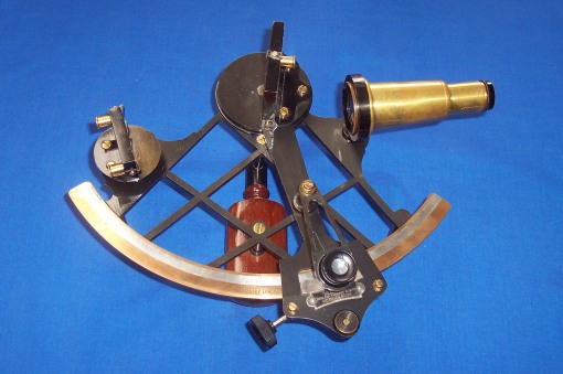
Older textbooks on surveying usually illustrated a nautical sextant in the chapter on instruments, but there is another category of sextant used specifically for hydrographical surveying: the survey or sounding sextant. As this was used to measure mainly angles between terrestrial objects in order to fix the position at which a sounding was made, there was no need for shades. The telescope provided was usually a Galilean of two to five power, sometimes provided with two eyepieces and, together with the mirrors, of larger size than usual for the period. Some were also provided with a peep sight.
Surprisingly for an instrument that must have been picked up and set down a large number of times when taking a line of soundings from a small boat, most sounding sextants were held in the right hand and had the legs on the same side as the handle. This meant that the sextant had to be passed to the left hand before it could be set down on its legs. Although they were mostly used with the frame horizontal, few were provided with handles that took this into account.
The following photo shows a sextant named Stanley. Unfortunately, this honorable name in the instrument-making world has been stolen by purveyors of so-called replicas of pocket or box sextants, but the firm of W .F. Stanley and Co was established in 1853 and were well known manufacturers and sellers of surveying and other scientific equipment into the second half of the twentieth century.
In 1926, they merged with Heath and Co, a respected firm of sextant makers. This sextant plainly came from their workshops, as demonstrated by the “‘Hezzanith’ Endless Tangent Screw Automatic Clamp” placard beneath the vernier scale.
The silver arc of 142 mm radius is divided up to 200 degrees though the instrument can usefully take angles only up to 140 degrees, beyond which the view of the reflected image is reduced to a very narrow slot. The vernier reads to 20 seconds.
The lozenge-pattern frame of cast bronze is rather delicate and, except for the arc, was only 8 mm deep. It was the least resistant to deflection of the C20 frames that I tested to include in Table I of my book, TheNautical Sextant . However, this is unlikely to have had much practical significance, given the class of observations it was used for. The black japanned finish is among the finest I have seen in any sextant.
The telescope is a little unusual in that it screws into its non-adjustable mounting at the objective end. It would otherwise foul the unusually large (for its time) index mirror. It is provided with two eyepieces giving magnifications of x 3 and x 5. The kit also included a peep sight, described as a “sighting head” in Stanley’s catalogue. This screws into the telescope mounting and is essentially a heavy, knurled brass disc with a central 2 mm diameter hole.
In taking a line of soundings, the preferred method was to set up two signals at known positions on the land, more or less perpendicular to the shore. These would be kept in line as the boat sailed out and a sextant angle was measured between the line and another shore object each time a sounding was taken. A more complex method is to take simultaneous angles between three shore objects of known postion and plot their intersection. This is the well-known, but perhaps little-used three point fix. W Norman Thomas’s Surveying (London, 1926) gives two mathematical and five geometrical methods of plotting the fix, but the preferred method was a mechanical one that used a station pointer (U.S. three-arm protractor), shown in the next photograph.
The two included angles are set on the instrument and the three arms lined up on the three points observed. The point of intersection is then pricked through on to the chart. Most of the station pointers I have seen have been vernier instruments reading to 20 or 30 seconds, but the one in the photograph, of Russian origin, has a pair of micrometers that allow rapid reading to one minute. The angles could of course less accurately be laid of on a piece of tracing paper and the fix pricked through.
The Admiralty Manual of Navigation Volume I of 1964 gives as the advantages of fixing by horizontal angles: a) it is more accurate than a compass fix; b) it is independent of compass errors; and c) the angles can be taken from any part of the ship. It says the disadvantages are : a) it takes longer than a compass bearing fix; b) three suitable objects are needed; and c) If the objects are not correctly identified or charted the fix will be false without the error being apparent.
Next in this series will be a Kelvin and Hughes survey sextant Mark III.


You must be logged in to post a comment.