Figures 5, 6, 12, and 13 may be enlarged by clicking on them.
During the Battle of the Atlantic, which for Britain began on 2 September 1939 and ended on 8 May 1945, without a break, Britain was nearly brought to its knees by submarine warfare. The battle began to turn away from Germany’s favour in mid-April, 1943, when for the first time convoys could receive continuous air cover between Britain and North America. It soon became apparent from increasing submarine losses that German submarines could no longer safely remain surfaced during daytime. While the Schnorkel ventilating tube mitigated this problem to some extent, by early 1943, the protection given by darkness was removed by the Allied development of airborne centimetric radar and the Leigh Light which illuminated the sea for attack once an aircraft had been guided to the submarine by radar.
In spite of having a Schnorkel, a submarine still had to surface to make observations of the stars, moon and planets at night, but as the horizon is generally not visible at night, an instrument with an artificial horizon had to be developed. I have described the SOLD KM2 bubble sextant in my post of 5 November, 2013. Unlike a large aircraft, which has at least partly predictable oscillations in flight, anyone who has taken a bubble sextant to sea will know that the accelerations as revealed by the bubble vary wildly and unpredictably. If the instrument is provided with a read-out that integrates observations over two or three minutes, as is the C Plath SOLD, it may be that results will be better than with instruments that simply average many observations at an interval that may coincide with the frequency of, say, rolling of the submarine. This potentially can lead to very large errors indeed.
When a bubble sextant is subject to an acceleration, all the fluid in the spirit level is affected. As you will see when I describe the gyro unit, when the Kreiselsextant is subject to an acceleration, the only connection between the sextant and the gyro is via its low friction, small area bearing. Effectively, the gyro is almost detached from the sextant and retains the direction of its axis of spin in space.
Figures 1 and 2 show the left and right hand sides of the Kreisel sextant. Apart from the gyro unit and minor changes to the light path, it is almost identical to the SOLD sextant, so I will describe only the gyro unit and the consequent light path changes in what follows. Readers interested in the interior of the instrument may consult my post of 5 November 2013.

Figure 1: Left hand side.
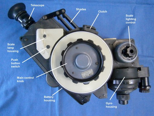
Figure 2: Right hand side
Figure 3 shows the gyro rotor sitting on it bearing in the bearing housing. The upper part is cross bored on a diameter, one end of which carries a collimating lens and the other a graticule at the focus of the lens, so that light rays emerging from the lens are parallel. When viewed, the image of the graticule thus appears to be at infinity. The lower part has 35 crescents, or buckets machined into its edge, so that when air is blown into them the rotor is caused to rotate. As the gyro rotates at hundreds of time a minute, the image projected into the sextant flickers only a little.
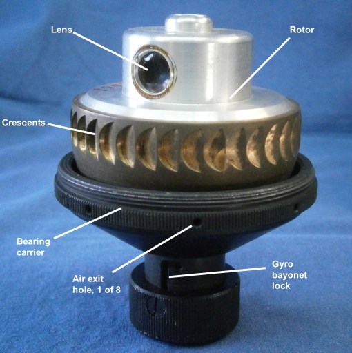
Figure 3: Gyro rotor on its bearing.
Figure 4 shows the image obtained of the graticule when viewed through the collimating lens. The central pair of lines are intended to be used for star observation, while the outer pair are used for moon and sun observations. The out-of focus vertical dark line is of course the central bearing spindle.
-

Figure 4: Graticule seen through collimating lens.
Figure 5 is a cross sectional drawing of the rotor and its housing, copied from a British analysis of the sextant reported in August, 1945. I have added the light path, The rotor has a hard steel spindle through its centre coming to a point of 0.13 mm radius. Together with a concave artificial sapphire of 3.7 mm radius, it forms a low friction, self-centring bearing for the rotor. The carrier for the sapphire is spring loaded within a lifting tube that can be raised to lock the rotor against the top of its housing.
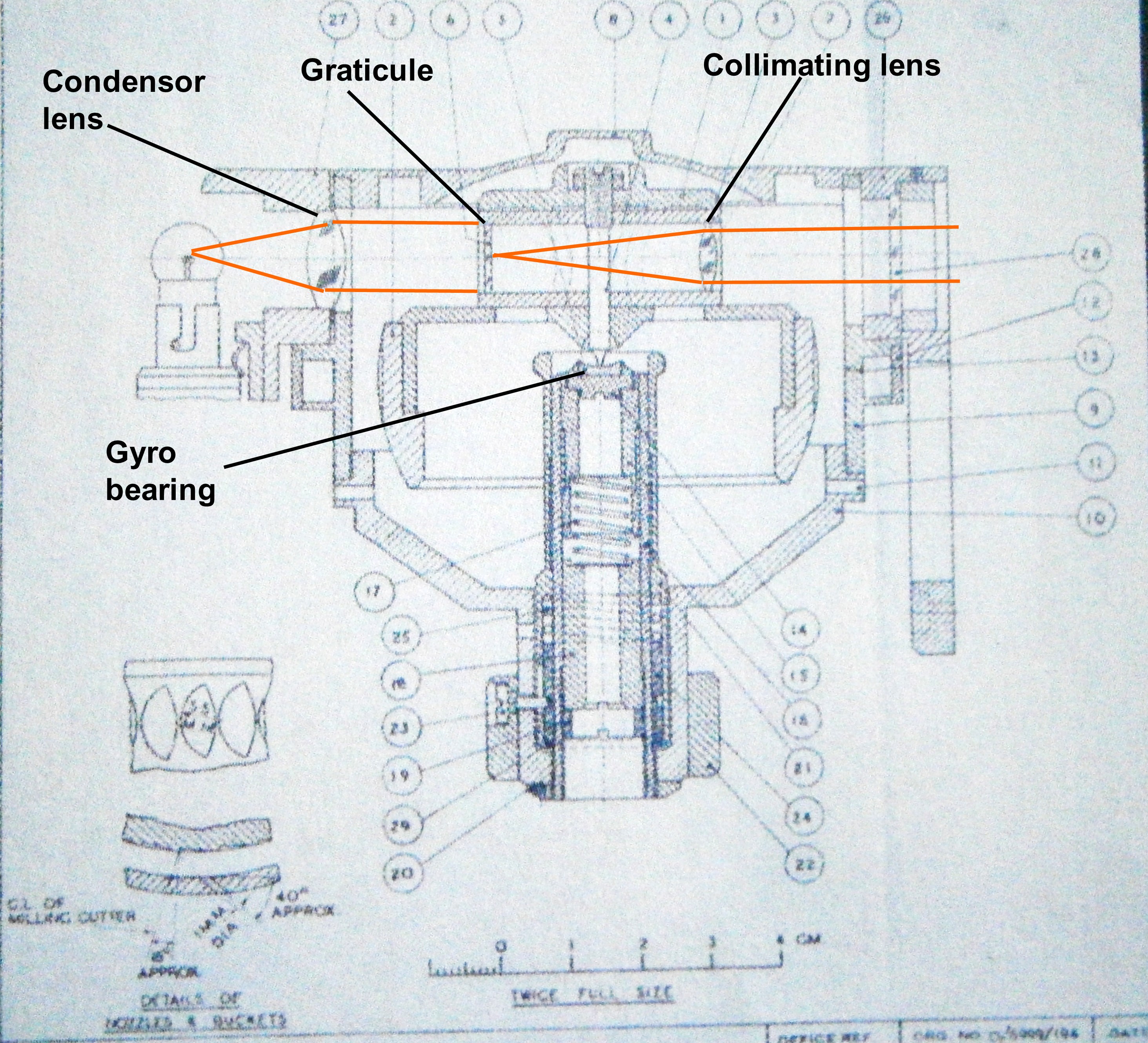
Figure 5: Sectional drawing of gyro.
Figure 6 shows details of the gyro bearing and the lifting tube used to lock the rotor.

Figure 6: Gyro bearing detail.
Figure 7 shows the window through which rays exit the rotor into the body of the sextant. Circled in white are two of the six tiny holes or nozzles through which air is projected into the buckets at high speed at about 40 degrees to tangential to make the rotor rotate at high speed. They are 1 mm in diameter.

Figure 7: Detail of interior of housing.
Air enters the nozzles from a gallery which is connected to an air inlet shown in Figure 8 below. The air leaves the gyro housing through 8 holes drilled in the circumference of the bearing housing. A flap covers a viewing window through which the motion of the gyro may be viewed to check when it has settled into a steady motion.
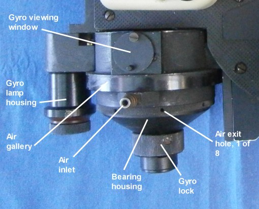
Figure 9: Exterior of gyro unit.
Figure 10 shows the lamp carrier for the gyro unit. It screws into the gyro unit. When I bought the sextant it came with three 3 volt bubs with the miniature bayonet base shown, all unfortunately defective. In this voltage they now seem to be unobtainable, but I was able to find some 6 volt versions, perhaps the last dozen on the planet, and had to make up a makeshift 6 volt battery pack that would fit into the sextant in order to try it out (Figure 11).

Figure 10: Detail of gyro lamp carrier.
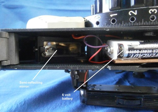
Figure 11: 6 volt battery pack in place
Figure 12 is of another drawing from the British 1945 report, showing the full light path. After being collimated at the rotor the image of the graticule is, I think, reverted by a pair of lenses, one applied to the face of a 90 degree prism and the second beyond a fixed mirror. This second lens appears to be at the focus of a further collimating lens that brings the rays parallel again, to be viewed in a Galilean telescope. (I am not confident that I have correctly described the function of the lenses between the two collimating lenses. If any reader can enlighten me further I should be glad to hear from them in the “Comments” section.)
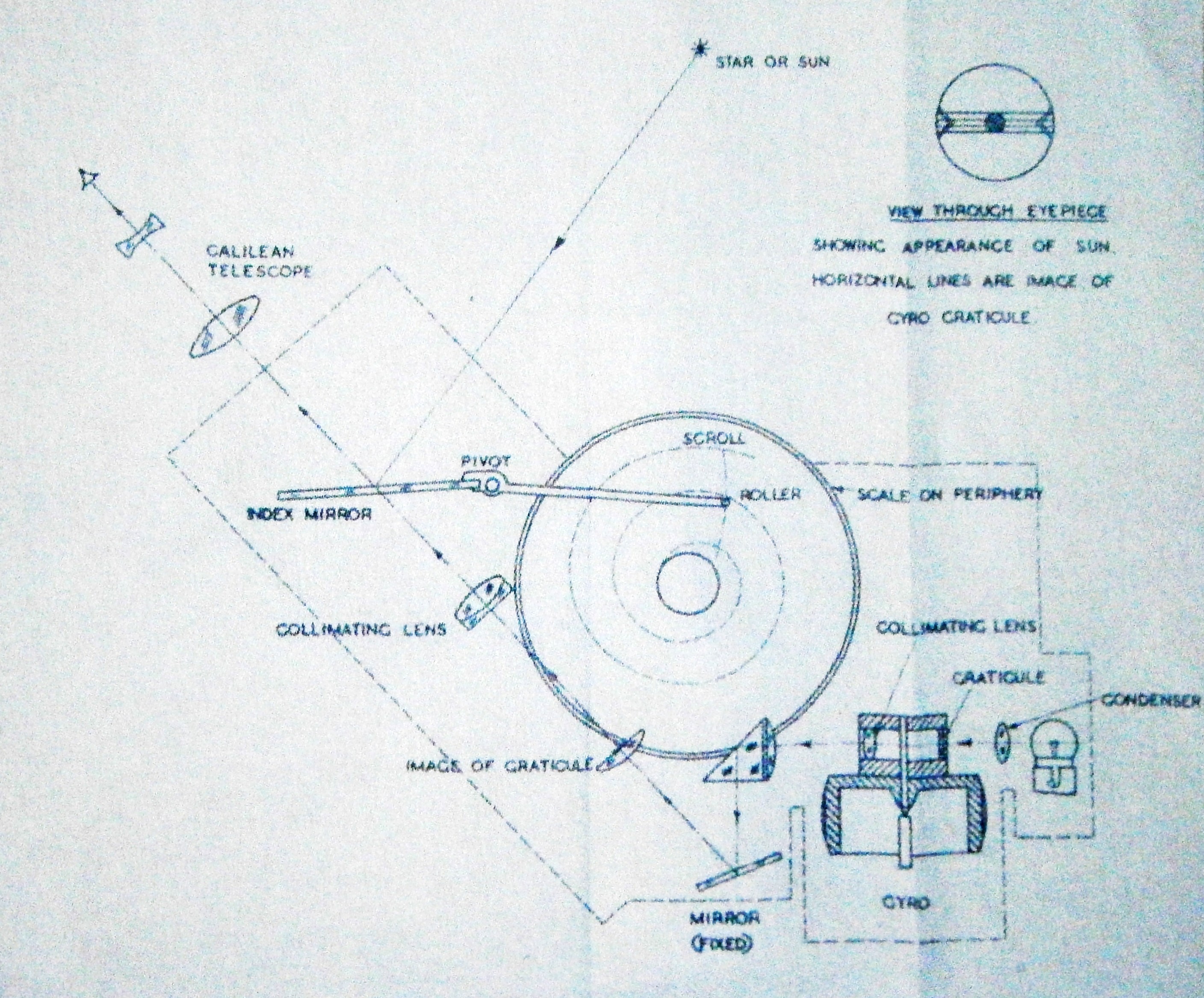
Figure 12: Light path through sextant.
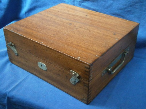
Figure 13 shows the instrument in its case. At top left is a carrying handle used to carry the instrument up through narrow confines of the conning tower hatches. Although it would not normally be used in daylight with a natural horizon, it is nevertheless provided with a set of four shades so that daylight observations of the sun or moon could be carried out on the uncommon occasions when the bodies are visible but not the horizon, e.g. in ice. A light shade would be needed for night observations of the moon when near full.
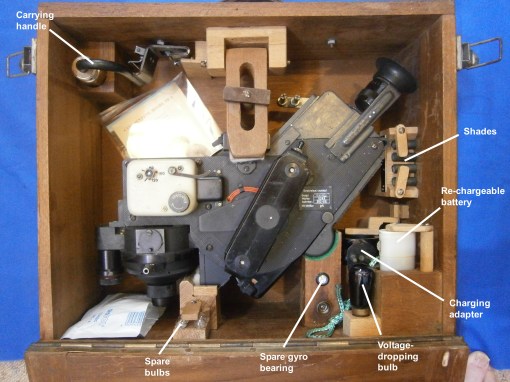
Figure 12: Sextant in its case, with accessories.
Below the shades is a charging adapter and blue bulb used as a dropping resistance to allow the white nickel-iron-alkali battery to be recharged from a 110 volt direct current supply. Proceeding clockwise, there is a spare gyro bearing and a bank of four spare bulbs. The sextant is held in the case by a bracket that folds down from above, which is then locked in position by a transverse bar. The sextant itself weighs just over 3 kg, but with its case it is a hefty 8.6 kg.

Figure:13 Instructions
The instructions, pasted to the inside of the lid, are of course in German, and there appears to have been at least two versions. It seems that the instrument in its case was to be set down on a table with the lid open and horizontal. An air supply probably from a foot pump, was then attached to the air inlet and pumped rapidly until the whirring of the rotor reached a high pitch, when the rotor was then allowed to settle down for three minutes, though this appears later to have been altered to five minutes. During this time, precession of the rotor settled down so that its vertical axis was aligned with local gravity, and the light path through it horizontal. The integrator was then wound up, the instrument eased carefully out of its case and the carrying handle clipped into place (Figure 14), all the time keeping the sextant upright and avoiding knocks or sudden movements.

Figure 14: handle in place.
Even removing it from its case needs great care, as it is a narrow fit and it is all too easy to catch it on some projection. The sextant is then passed from hand to hand up the conning tower, all the time avoiding sudden movements and knocks. On reaching the top, the handle is then unclipped. The spring is strong and again it is quite difficult to do this without upsetting the gyro. The main switch on top of the left handle was then switched on and the gyro lighting control in the left handle (Figure 1) adjusted and a view of the graticule obtained. The gyro lighting comes on only when the integrator is wound up and goes out when the integrator runs down, signalling the end of the observation period to the observer. The lighting of the integrator read out then comes on and its intensity can be adjusted using the scale lighting control (Figure 2). Pressing the button switch on the scale lighting cover (Figure 2) causes the integrator lighting to go out and the lighting to the remainder of the scales to come on.
The cone of visibility of the graticule is quite small and it needs a little practice simply to obtain a sight of it on dry land. I imagine it would need much practice to see it and then make it coincide with a star on a submarine at sea, but we know from at least one voyage report that this was done successfully, though we do not know with what degree of accuracy. Hand held, on dry land, the mean error of 50 observations of the sun was 10.9 arc minutes, with a standard deviation of 8.86 minutes.
As spinning tops as toys have given way to electronic games at all ages, some readers might wonder how it is that the gyro comes to define the vertical with its axis and hence provide an artificial horizontal via the graticule and collimating lens. Another way of putting the question might be: why does a spinning top stand up, but this is somewhat complicated because at rest in this gyro, the rotor is stable, as its centre of mass is 3.5 mm below the bearing.
The law of conservation of angular momentum decrees that undisturbed, a rotating body will continue to maintain the direction of its axis of rotation unless a force acts upon it. The only available forces are gravity and friction in the bearing and, as I have noted above, the end of the spindle is spherical, with a radius of 0.13 mm, so that when leaning, the centre of mass does not coincide with the centre of the spindle. This with gravity creates a couple, which leads to the axis describing a cone, or precessing until the centre of mass is coincident with the centre of bearing, in which position it is upright.
Readers of a mathematical bent (which I am not), will find a more lengthy and satisfying explanation in most university level textbooks of physics and mechanics. In 1890, J Perry published an entertaining little account of a popular lecture he had delivered, “Spinning Tops,” in which the words, “vector,” “angular velocity” and “torque” do not appear. General readers may find in this a more accessible account.


You must be logged in to post a comment.