One of the commoner parts to be broken when sextants are dropped or break loose from their moorings in the case is a leg. Legs are often rather long and slender with a correspondingly small diameter to the screw thread that attaches them to the frame. A typical thread outside diameter would be 4 mm and the core diameter of an M4 thread is a mere 3.3 mm. Usually, the threaded part breaks off, leaving a short stub behind on the leg. This post is mainly about extracting the threaded part from the frame.
Extracting large threads is relatively easy. One just drills a hole approximately down the middle and inserts an “Easy-out”, a hardened tapered tool with a coarse left hand thread cut on it. As it is screwed into the hole (left handed of course) it eventually jams and continued rotation extracts the broken stub. However, the threads used on sextant legs are too small for this to be an option, and more care is needed. Figure 1 shows the starting point, as found in an antique Observator sextant. The thread is M4, with a tapping size of 3.3 mm.
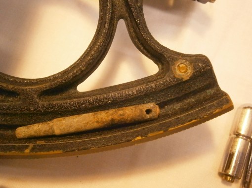
Figure 1: Broken leg as found
Two centre punches are needed, one with a sharp point with an included angle of about 40 degrees, sometimes called a prick punch, and another with a greater included angle, approaching about 90 degrees. Both need to be sharp. Using a strong hand lens the centre of the stub is located (Figure 2) with the prick punch and very light pressure applied, just enough to make a tiny depression.

Figure 2: Marking the centre.
This is checked for centering and if it appears to be off-centre, it is coaxed in the right direction by applying light sideways pressure and then uprighting the punch to apply a little more. If satisfactory, the prick punch is given a light tap to deepen the punch mark. [As an historical aside, this method of “coaxing” marks into their correct position was used by Jesse Ramsden when originating his dividing machines some time before 1777.]
This fine punch mark is then deepened and widened with the other punch (Figure 3), carefully exploring with the tip until you are certain that it is located correctly in the fine mark. Give a light tap at first and then check you are in the right place. Follow up with a heavier tap.

Figure 3: Enlarging the centre punch mark
This larger punch mark now guides a drill, starting with a small diameter (Figure 4). About 1 mm seems to be about the correct size, so that the drill point is guided almost entirely by the walls of the punch mark and not deflected by irregularities in the surface of the stub.

Figure 4: Fine drilling.
A sensitive touch is needed with the drill, as one does not want it to come out on the face of the frame. Happily, there is usually a little space beyond the end of the stub and the drill can be felt breaking through. If you are confident that the drill hole is correctly centred, you follow up with a larger drill, in this case, one of 3 mm and if it still seems to be correctly centred, finish with one at tapping size. If it is off centre, increase the size of drill used until one wall of the tapped hole is reached and then pick out the remnants of the stub. This is most easily done with a tap of the correct size, but a stout scriber will also do the job. Figure 5 shows the final result of doing this.

Figure 5: Female thread liberated.
Preparing the leg is a matter of simple turning, though I imagine it could also be done with a file and hand drill. First the remains of the stub are faced off in the lathe and a hole of the correct tapping size drilled down the leg. This is then tapped and a screw of the correct size inserted until it jams. I generally add a small drop of Loctite to make sure, before cutting off the screw to a suitable length. Figure 6 shows the prepared leg ready to be inserted into the threaded hole in the frame.
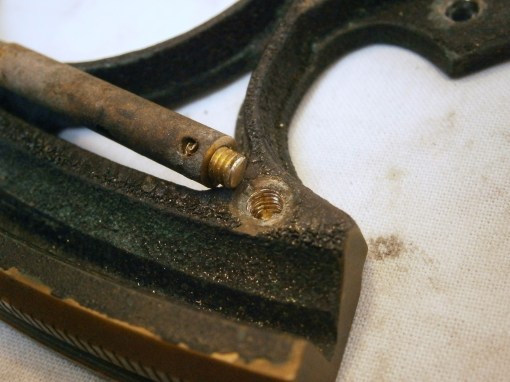
Figure 6: New male thread inserted.
This method of drilling out a broken stub of thread can of course be used elsewhere when restoring instruments, though especial care needs to be used when the thread, say of brass, is stuck in a hole made of a softer metal like aluminium alloy. If the drill drifts off centre it may take the path of least resistance through the softer metal, leaving a mutilated stub and a new hole in the wrong place. This may need some creative bodging to correct…

You must be logged in to post a comment.