This post was preceded by “Making a shades adjusting tool” and “Eighty years of Carl Plath Sextants”. Other posts on C Plath sextants may be found by entering “C Plath” in the search box on the right. All figures may be enlarged by clicking on them. Return to the text by using the back arrow.
Several makers, including C Plath, made sextants directed at the yachting market with more or less success. There seems to be a fair number of Freiberger yachting sextants around, but I have only ever seen two Plath Yachtsman sextants. In the years after WWII, many full-size sextants must have flooded the market, especially the USN Mark II sextant and those made by Henry Hughes and Son. The latter also made half size sextants for use in sea planes and presumably they were attractive to yachtsmen, as some have survived. A variety of plastic sextants derived from the Maritime Commission version for lifeboats came on to the market and evolved into instruments that looked like “proper”metal sextants, though few were rigid enough to behave like one. Francis Barker produced a box sextant labelled “Small Craft Precision Sextant” intended for sale to yachtsmen, but despite having been provided with a horizon shade and an eyepiece shade in addition to the usual index shade, I doubt that it found much favour with nautical users. A box sextant is a fiddly instrument at the best of times and it is difficult enough to take sights from a rolling yacht. Ilon industries made an ingenious little micrometer sextant provided with a tiny prismatic monocular (https://sextantbook.com/category/ilon-industries-sextant/) that may have found favour with the well-heeled and Tamaya made a light weight 5/6ths sized micrometer sextant. The French firm of Roger Poulin made an interesting little sextant that was plainly aimed at the yachting market and I have described it here: https://sextantbook.com/?s=Poulin .
It is not clear whether the yachtsman wished a smaller sextant because of lack of space aboard yachts or because a smaller sextant might be cheaper than a full-sized version. At any rate the saving in space and weight must have been insignificant, and the savings made by buying a smaller sextant cannot have been great when compared with the cost of the vessel.
Unlike the Freiberger Yacht Sextant (https://sextantbook.com/?s=Freiberger+yacht), which attempts in a way to echo the full sized instrument, the frame of the C Plath sextant is monolithic and exceptionally rigid. Figure 1 shows a general view of the front. The bases of the index and horizon mirror brackets are identical though the horizon mirror itself is half silvered. Both are circular, presumably because it is easier to seal the mirrors against the intrusion of salt water behind them, but as can be seen in some of the later figures, the index mirror has suffered around the edges. The two index shades and one horizon shade are adequate in most circumstances. Their brackets are simple and no provision is made for adjustment of friction. A notch in the edge of the frame allows the horizon shade to be folded completely out of the line of sight.
The rack in which the micrometer worm engages in machined into the edge of the limb, together with a slot for a keeper to keep correct engagement. The radius of the rack is about 140 mm (5.5 ins) and the instrument weighs 1260G (2lbs 12 oz).

Figure 1: General view of front.
The telescope has a simple draw tube for focusing, and has an aperture of 25 mm and a power of about 2.5 diameters, giving a field of view of a little over 6 degrees. This is about the same as one gets from a 4 x 40 mm telescope of a full-sized instrument. Though a C Plath leaflet says the aperture is 30 mm with a magnification of x 4, the inside diameter of the tube in front of the objective lens of my sextant is only 27.5 mm and it has to sit on a shoulder, so the aperture behind the lens is only 25.1 mm. The measured magnification is about x 2.5.
The telescope is not demountable, a disadvantage on a small vessel when it is rolling and pitching, as with a standard field of view it can be difficult to acquire the heavenly body and bring it down to the horizon. Removing the telescope altogether makes it much easier to find the body and to bring it down, when the telescope can be replaced and the horizon swept to re-acquire the body. However, the telescope mounting is very robust so that it is not only resistant to knocks, but the sextant can safely be picked up by the telescope without fear of damaging or displacing it. The micrometer mechanism is well protected against knocks and the release catch is simple to operate. Figure 2 shows a rear view of the instrument.

Figure 2: Back view.
The frame is closed off at the back by a back plate, which is attached to the frame by three screws and a leg. The handle, adapted from a full-sized instrument battery handle, is attached to the back plate via pillars by two countersunk screws. Removing the back plate reveals the index arm as shown in Figure 3. Note that if the sextant gets drenched in salt water, it is an easy matter to rinse out the interior with fresh water without necessarily removing the back plate.
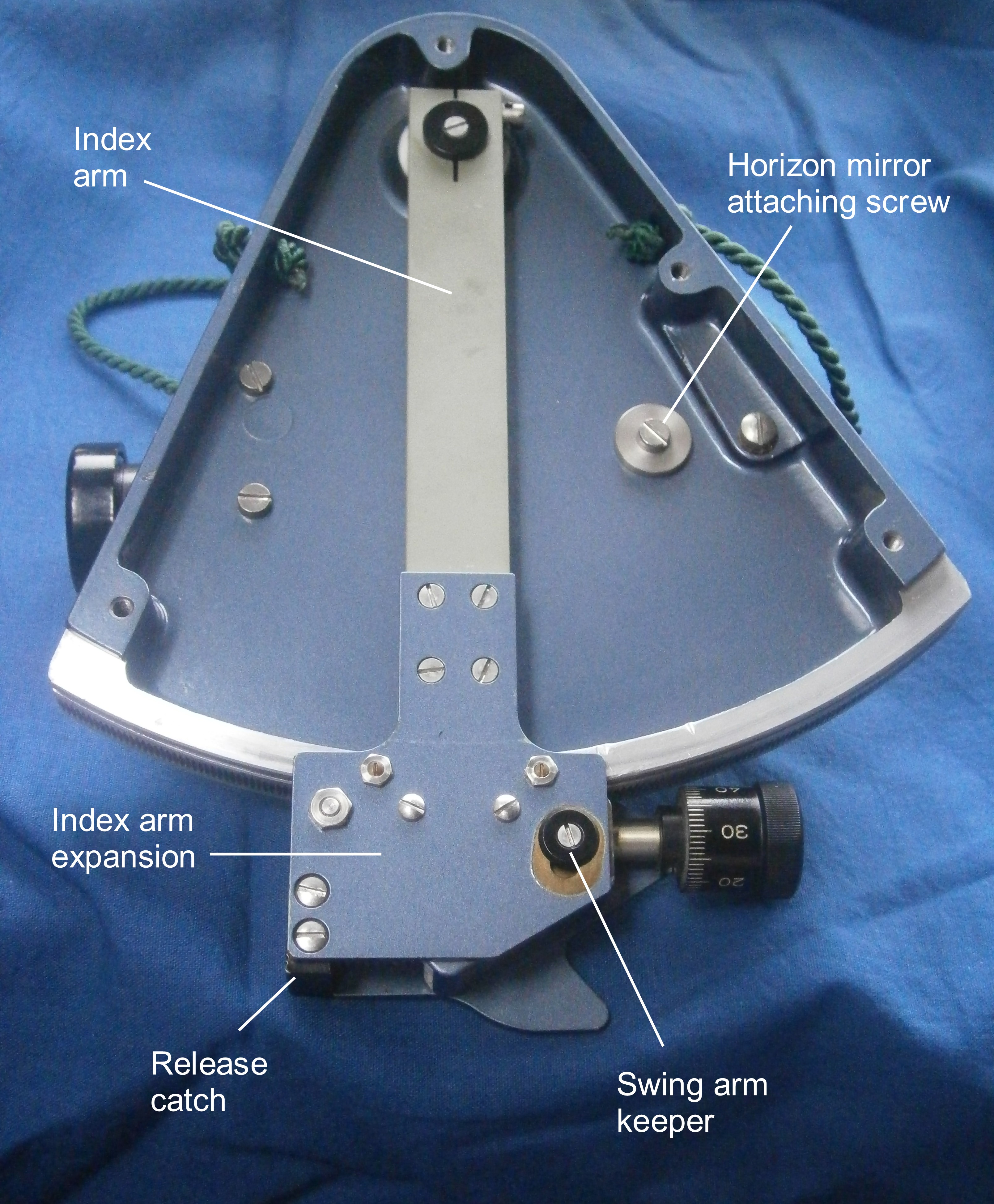
Figure 3: Rear view without back plate.
The index arm is in two pieces: a stout rectangular bar attached to the index mirror bearing at the top; and a plate that I have christened the index arm expansion at the bottom. This plate carries the micrometer mechanism. I have labelled the screw for attaching the horizon mirror and the swing arm keeper in Figure 3 for future reference below. Also seen are the two stout screws that attach the telescope to the frame.

Figure 4: Index arm bearing.
The anatomy of the index arm bearing is revealed in Figure 4. A micro-finished journal runs in a parallel bearing machined directly into the frame, with two PTFE washers acting as spacers and also taking any minor thrust forces that may arise. A flange above the journal carries the index mirror in its bracket, while a spigot below attaches the index arm. Figure 5 shows how the upper end of the index arm is split, with a pinch screw to close it around the spigot. This allows adjustment of the mirror in the horizontal plane as well as axial adjustment to take up any axial movement in the bearing.

Figure 5: Upper end of index arm.
Figure 6 shows how the index mirror is adjusted for perpendicularity and the horizon mirror for side error (the horizon mirror is illustrated) . The mirror bracket is rocked by means of two screws about two ball bearings sitting is depressions to form an axis of rotation.
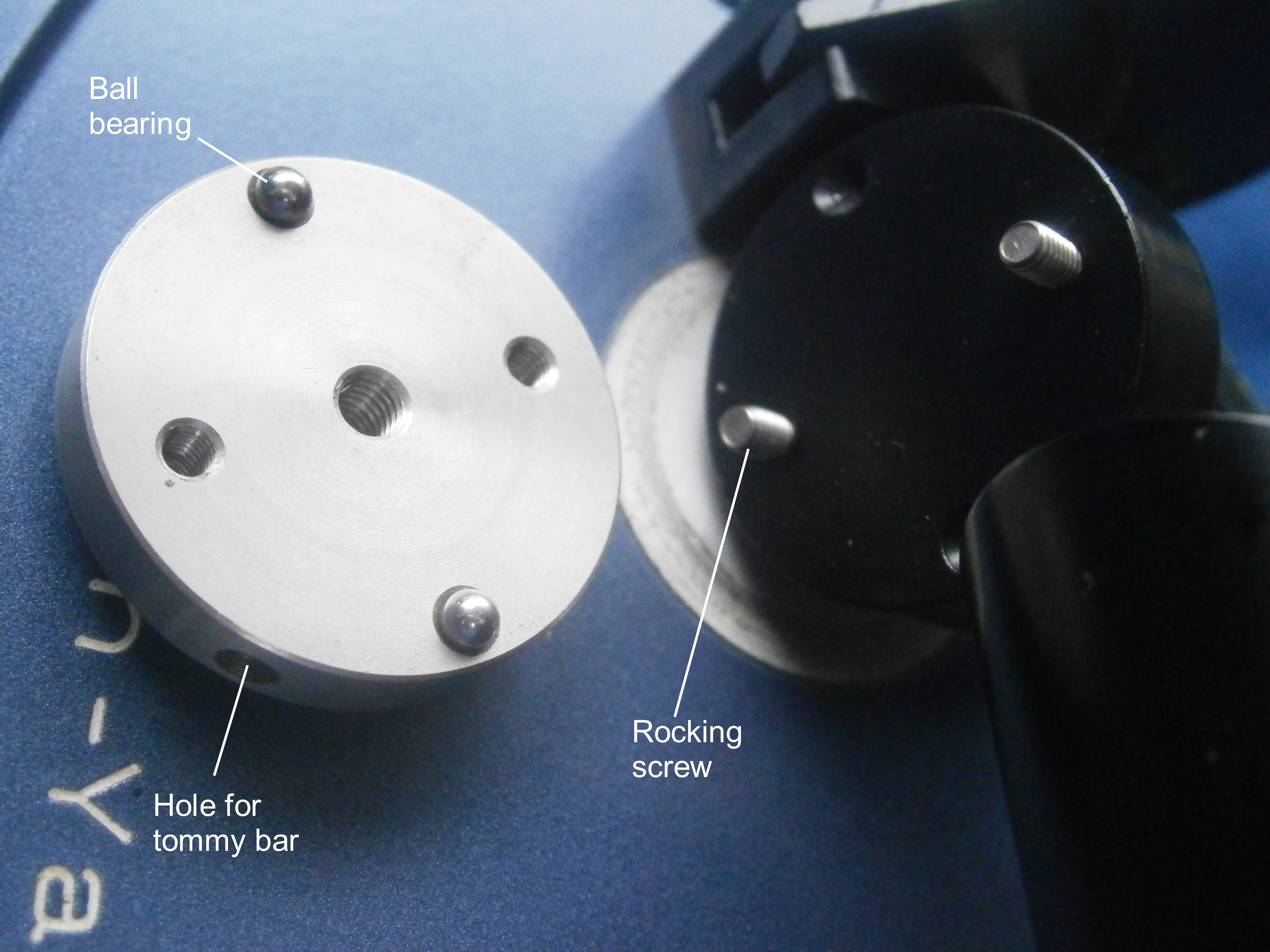
Figure 6: Mirror bracket adjustment.
As the reflective surface of the index mirror lies a little ahead of the axis of rotation of the index mirror it is necessary to use two vanes to raise the line of sight to somewhere near the centre of the mirror, as otherwise a minor error in perpendicularity may be introduced. Figure 7 shows how two small dominoes have been used, but any two identical objects objects of about the right height may be used, such as pieces cut from aluminium or steel angle, large hexagonal nuts or large rollers from a scrapped roller bearing. One is placed on the limb of the sextant at zero and the other at about 90 degrees. The index arm is then rotated until a reflected view of the second vane is seen alongside a direct view of the first, when the mirror is adjusted to bring their tops into line as shown. In many sextants, including this one, it may be necessary to remove the telescope and/or index shades to obtain the required view.

Figure 7: Adjusting index mirror for perpendicularity.
When adjusting the horizon mirror to remove index error, the screw arrowed in Figure 3 is slackened and a tommy bar used in the hole visible on the right in Figure 7 to rotate the whole base. This is a relatively coarse way of adjusting and may involve much trial and error, but once done, the whole set-up is rigid and not likely to drift out of adjustment in a way that is so annoying with plastic “instruments”. Removing side error has already been mentioned in the paragraph following Figure 5. Note that index error cannot be removed by using the sun, as the single horizon shade is not dense enough for this method. There is no adjustment available for collimating the telescope, but quite large errors of collimation have relatively little effect on the accuracy of readings, especially for the class of sight likely to be made with this instrument. In any case, this is taken care of at manufacture and would require very rough handling indeed to disturb.
The micrometer mechanism is robust and well-protected. Figure 8 shows it detached from the index arm. The black release catch on the right in fact remains stationary when disengaging the worm and it is the horn extending down and to the left on the plate that rotates when it and the black catch are squeezed together.
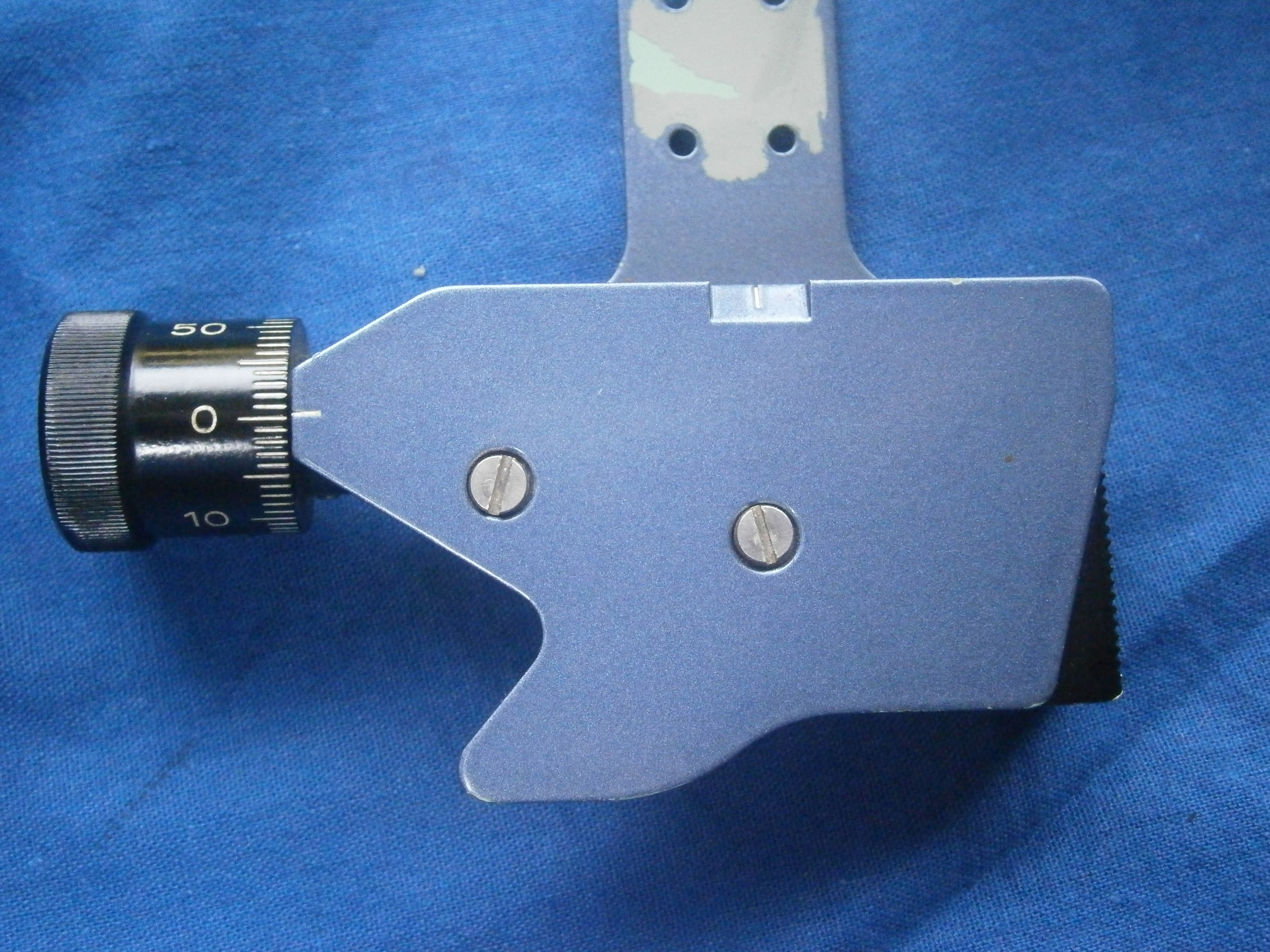
Figure 8: Micrometer mechanism detached from index arm.
In Figure 9, the front plate which carries the fiducial lines for the degrees scale and the micrometer has been removed to show the swing arm chassis. This carries the micrometer worm in a plain parallel bearing, the axial play of which is taken up by a leaf spring. A swing arm extends upwards and to the right to a bearing in the form of a shouldered screw, about which the chassis rotates. A stout helical spring keeps the worm in engagement with the rack machined on the edge of the limb of the sextant.
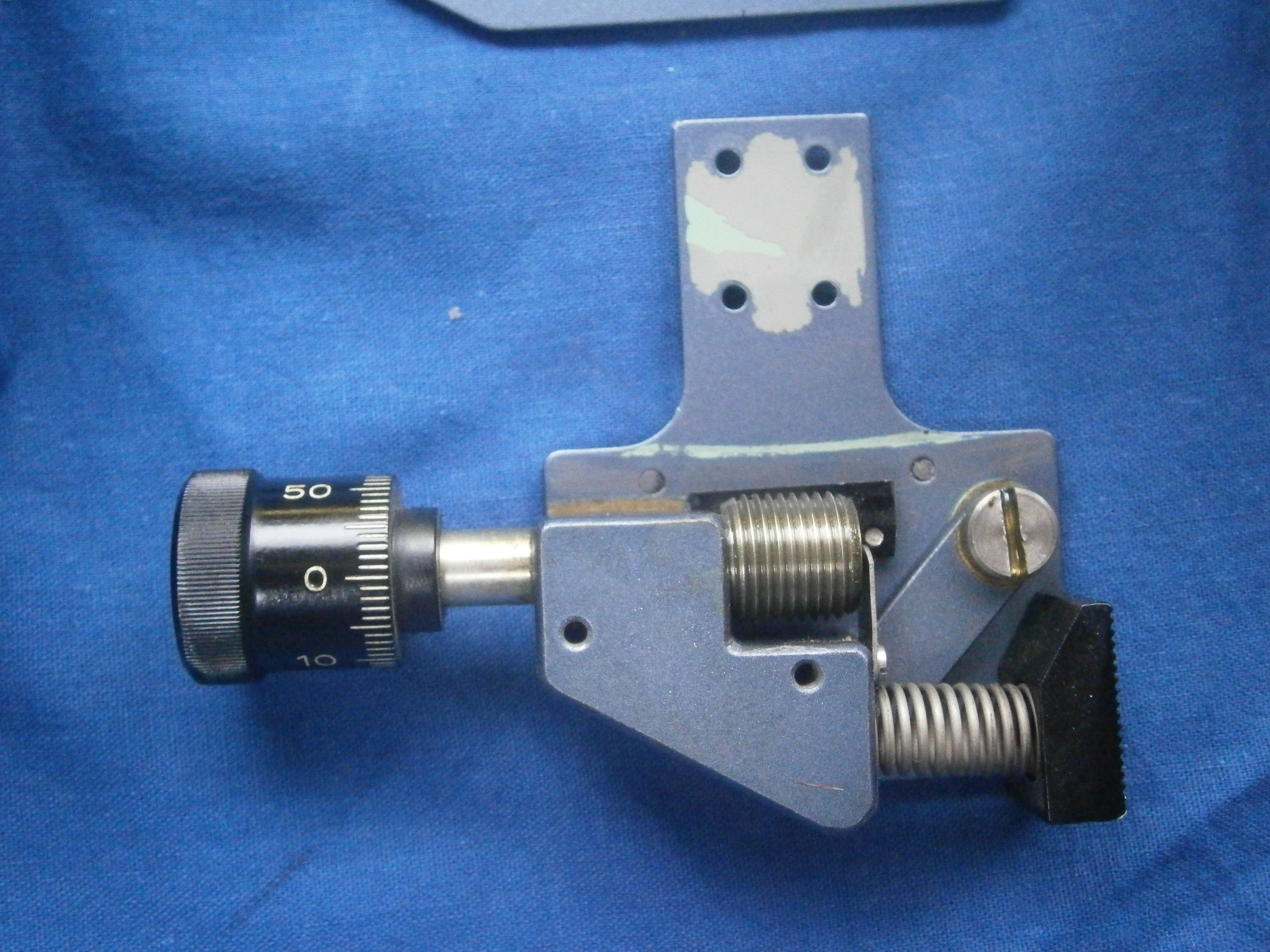
Figure 9: Front plate removed to show interior of micrometer mechanism.
Figure 10 shows these parts more clearly. In addition, there is a rectangular keeper that guides the index arm expansion and keeps the worm in correct engagement. It slides in a slot machined in the limb below the rack.

Figure 10: Micrometer mechanism exploded.
A further, circular, keeper ensures that the swing arm chassis cannot lift off the face of the index arm expansion. The spigot on the keeper slides in the oval slot and the keeper is retained in the chassis by means of a screw whose tapped hole is shown in Figure 11, centre, which illustrates the bearing surfaces for the swing arm chassis. The keeper can be seen in place in Figure 3, above.

Figure 11: Swing arm bearings.
The sextant frame, being made of aluminium alloy, is inherently resistant to corrosion, but parts that do not run together have a tough coating of blue paint. Other parts are made of bronze and all the screws and springs are of stainless steel. If the sextant should receive a soaking, it is a simple matter to rinse it with fresh water and allow it to dry, as all the parts of the interior are accessible. Nevertheless, at overhaul it would be wise to use waterproof marine grease for all moving parts except for the rack, which should receive SAE 30 lubricating oil, brushed into the rack with surplus being brushed and wiped off.
The case provided was, like so many other sextant cases over the last fifty years, made of plywood. Quite why the makers did not usually specify marine grade ply is a mystery, as many of them, including those from C Plath, suffered from delamination if stored damp. It was stored face down in the case, leaving the handle ready for use, but as it cannot be set down on a table face down, this is a limited advantage. Perhaps though, it was to discourage users from leaving it in a position on a table to slide onto the floor. The general rule is that a sextant should be in the user’s hand or in its case, relatively easy to follow on a yacht, but more difficult on the bridge of a large ship. All in all, this is a robust sextant, well suited to its task.
Dr Andreas Philipp writes that at least 900 of these sextants were made from 1968, starting with a serial number of 101. They were sold mainly in the USA.

You must be logged in to post a comment.