Previous posts in this category include: ” A turn-of-the-century French sextant”, “A Half-size Sextant by Lefebvre-Poulin”, ” A Fine Sextant by Spencer, Browning and Co”, “A C19 Sextant Restoration” , “Making a Keystone Sextant Case” , “Restoring a C. Plath Drei Kreis Sextant” , “Heath Curve-bar sextant compared with Plath” , “A Drowned Husun Three Circle Sextant”, ”Troughton and Simms Surveying Sextant” , “A Sextant 210 Years On” , “A fine sextant by Filotecnica Salmoiraghi”, “A British Admiralty Vernier Sextant”, “An Hungarian Sextant via Bulgaria” , “A Half-size Sextant by Hughes and Son” and “A Fine C Plath Vernier Sextant”, “Heath and Co’s Best Vernier Sextant.” and “An Early C19 Ebony Quadrant Restored”.
A month or two ago, I acquired an ancient ebony-framed quadrant in a sorry state, with several important parts missing. Figure 1 shows the front view of the instrument as received and Figure 2 shows the back.

Figure 1 : Front, as found.
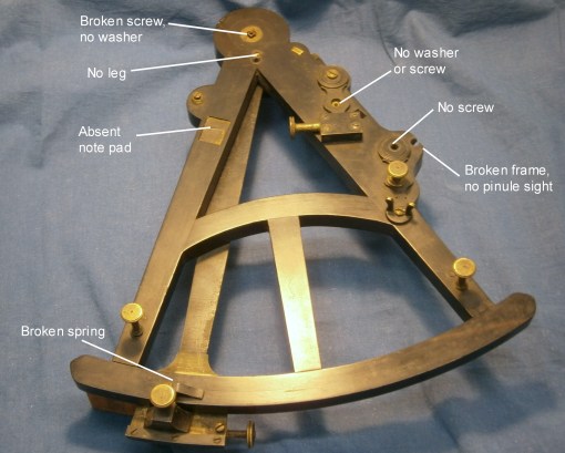
Figure 2 : Rear as found.
The pictures show clearly what was missing and damaged so I will not list them here, but instead digress to try to estimate the date of the instrument. Many ebony-framed octants were made and were often called “Hadley’s quadrant” or simply “a Hadley”. Most of them bear no maker’s name, though some of them, if divided by Ramsden, will bear evidence of this on the main scale. Hand-divided quadrants were of a large radius, 15 inches (380 mm) or more. The improvements due to Ramsden-type dividing engines allowed the radius to be reduced with no loss of accuracy, and most nineteenth century wooden instruments had a radius of about 9 inches (230 mm). The size of my new example lies somewhere between, at about 11½ inches (290 mm). Early illustrations of quadrants in use often show it being held by the frame, as no handle was provided, and the absence of a handle or any trace of one ever having been present, leads me to believe that this quadrant is relatively early, but after the advent of machine dividing in around 1767 (the description of Ramsden’s second engine was published in 1777 but his first engine dates to perhaps ten years before this).
Two further archaic features are the presence of a back sight pinhole or pinule and the design of the mirror brackets. I will borrow the words of W E May in his “A History of Marine Navigation” (1973, ISBN 0 85429 143 1) to explain the back sight: By altering the angle of the horizon glass and moving the eyepiece to a position close to it on the same radius, the octant could be used for what was called a ‘back observation’, when the horizon opposite to the object instead of below it was used. The angle measure was then the complement of the altitude….It is extremely doubtful whether the back observation was ever used in practice.” The light rays reaching the secondary mirror and pinule from the index mirror pass through the clear part of the normal horizon glass before being reflected into the eye by the secondary mirror, while the horizon is viewed through a slot in the silvering of the latter (Figure 3).
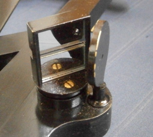
Figure 3 : Mirror and pinule for back sight.
Although the index mirror bracket was absent, the other two mirror brackets allowed me to study the design. Two screws pass through threaded holes in the back of the bracket and bear upon the back of the upright of an angle bracket. The vertical edges of the bracket are folded over so that when the screws are tightened, they draw the mirror back against vertical ridges on the front of the upright. Figure 4 shows the edges of the new index mirror bracket being folded over a steel pattern.
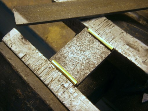
Figure 4: Edges of new index mirror bracket being formed.
If the ridges on the upright do not lie in the same plane, the mirror glass will be distorted and Peter Dollond pointed this out to Nevil Maskelyne, the Astronomer Royal, in a letter of February, 1772 and there is a reference to it in Phil. Trans. LXII, p291, 1772. Among other matters, he described the now modern practice of sitting the mirror against three points and with springs or lugs on the front of the bracket bearing on the mirror opposite these points. Figure 5 shows this practice had been adopted in a sextant made in about 1790.

Figure 5 : Peter Dollond’s method of securing mirror.
Thus, I tentatively date the quadrant as being after 1767, but not much later, as Dollond’s method of securing mirrors seems to have been rapidly adopted.
To return to the construction of the new index mirror bracket, after folding the sides and forming the retaining folds on the edges of their front I soldered the top to the sides. Figure 6 shows this being done, with a weight used to hold everything in place while the solder froze.

Figure 6 : Soldering top of index bracket to back and sides.
The holes for the fixing screws can be seen and after filing the top to its final shape, I riveted two threaded bushes in place. Figure 7 shows an exploded view of the completed bracket with its angle plate, while Figure 8 shows the completed bracket and mirror in place.
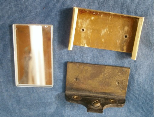
Figure 7 : Index mirror and bracket, exploded view
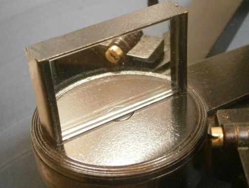
Figure 8 : Completed Index mirror bracket.
The next part to receive my attention was the pinules or pin hole sights. Actually, the holes are about 2 mm in diameter, rather larger than your usual pin…
All that remained to guide me was the base of one of them, so I laboriously cut out two discs of 3 mm brass sheet, filed them to shape and married one of them to the existing base by cutting a slot in it, applying solder and smoothing to shape with a file (Figure 9). I copied the base for the other sight. The standard sight has two holes in in, one in line with the silvered edge of the horizon glass and the other a few mm higher, so as to admit more light from the horizon to the eye when there is poor contrast between the sea and the sky. Even small increases in light intensity give worthwhile increases in contrast. I also fashioned a little cover (visible in Fig 11) that can be swung into place to cover one or other of the holes. The back sight has only one hole, aligned with the slot in the silvering of its mirror.
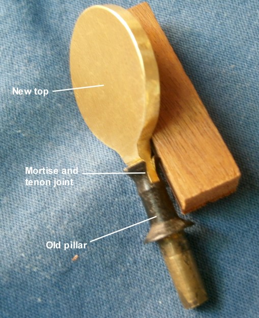
Figure 9 : Pin hole sight repair.
If you compare Figure 3 with Figure 10, you will see that in the latter , there is a defect in the wood of the frame. I made this good with car body filler, stained black with grouting stain, and then sanded to shape and smoothness, followed by a few coats of French polish until it matched the finish of the surrounding wood.
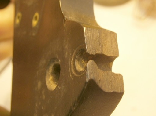
Figure 9 : Damaged frame (see also Fig 3)
The missing horizon shade glass was replaced by a disc of ruby red glass, which I cut out with a trephine. If you look carefully at Figure 1, you will see a rectangular slot just below the base of the horizon shade on the photograph. This is also visible on the back, and there is a further slot higher up which is occupied by the base of the horizon shades, so that the latter can be, as it were, unplugged and transferred to the lower slot, to provide shades when using the back sight.
Apart from a general clean-up and fitting a piece of Ivorine for the name plate, that completed repairs to the front. The most important item missing from the back was the washer and screw that secures the index arm bearing journal to the frame. Unfortunately, the screw had broken off and I had to drill it out and re-tap for a slightly larger size, but the washer presented no problems. The square hole in the washer has to fit closely over the square on the end of the bearing, as any tendency for it to turn might tend to loosen or tighten the screw and affect the adjustment of the tapered bearing.
It was a relatively simple matter to copy one of the legs and to make sundry new washers and screws. Two thumb screws lock the adjustments to the index and back sight mirrors and it was not too difficult to copy the remaining one. Happily, the threads seemed to be threads for which I have long-obsolete taps and dies, so I did not have to resort to the lathe to cut them. I have covered some of the details of the structure and adjustment of these parts here: https://sextantbook.com/?s=crichton
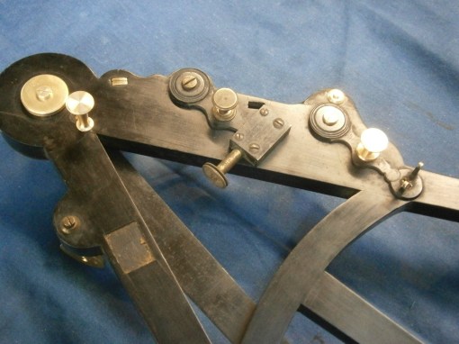
Figure 10 : Details of replacement parts on back.
A piece of clock main spring, after some persuasion, provided the replacement for the broken spring that holds the index arm against the frame, leaving only a small piece of Ivorine to be let in, to replace the missing note pad.
On completely dismantling the instrument to clean the frame, I found a couple of minor cracks in the wood, which were easily closed up after infiltrating some glue with a fine blade and clamping. I cleaned the frame with a mild detergent and then gave it a coating of good quality furniture wax. Most of the brass parts would not have been left bright, so they received a coat of black lacquer. Figure 11 and 12 show the finished article.

Figure 11 : Front with finished parts before painting.
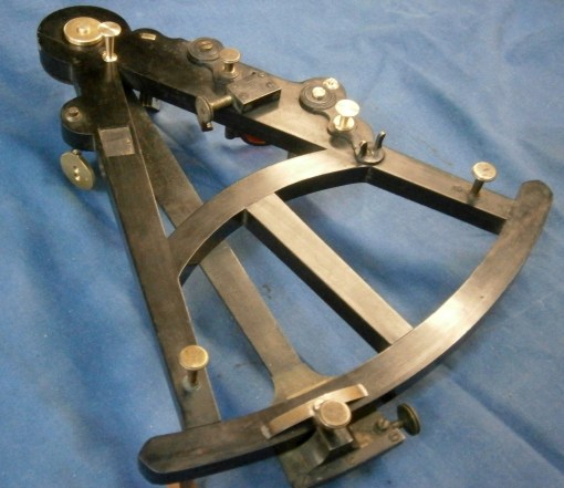
Figure 12: Rear before painting of replacement parts
The scales were in good condition apart from an incrustation of dirt which was easily cleaned with a little alcohol on a rag. Close inspection showed the ghost of some emblem, scarcely visible to the naked eye, between 45° and 50° (Figure 13).
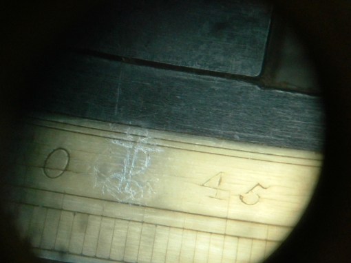
Figure 13 : Ghost of Ramsden?
After careful cleaning with a fine point and playing with the lighting, a fouled anchor emerged under magnification, but, while this was an emblem used by Ramsden on ivory scales which he divided for others, and there are other pointers to its date, it seems to me to be too crudely drawn, compared to the rest of the scale. Perhaps it was intended to deceive a buyer at some point in its long life.
The quadrant came to me without a home and I thought it deserved a case in keeping with its antiquity. They were at first “keystone” cases, but by the mid nineteenth century they had been replaced by square cases, partly because of the complication of making the bow front and partly because they are very awkward to carry. It is also more difficult to cut dovetail joints on an angle. However, I had succeeded twice before in making acceptable keystone cases so I set about making another one.
No doubt, in the seventeenth century, bending wood to shape was a commonplace task, as boats, ships and barrels, to name but a few, all needed their parts to be steamed and bent to shape. However, nowadays, it is possible to cut thin planks and we have glues that are strong, durable and waterproof, so I chose to laminate the front. Figure 14 shows three 3 mm laminae held in place in a mould while the glue dries.

Figure 14 ; Gluing up the laminae.
Cutting the dovetail joints proved to be no more than ordinarily difficult. The most difficult part was to cut the case into lid and base, once the top and bottom planks had been glued on. The saw always seems determined to wander, so that careful planing is afterwards needed to ensure a nice fit of the lid and hinges. Figure 15 shows the finished case and Figure 16 shows the completed quadrant in its new home.
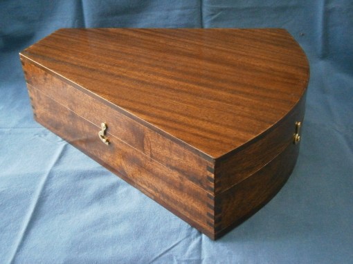
Figure 15 : Finished case exterior.

Figure 16 : Completed instrument in its new home
Museologists seem to be reluctant to do anything other than clean objects that they receive and I was told by one that if I did anything else I would receive a metaphorical slap on the wrist. My own view is that if we know for sure what the intact object looked like and that it is not excessively rare and valuable, to show it in, say, the state as in Figure 1 and 2, is less likely to educate a viewer that if it were restored. A compromise might be to leave the new and restored parts obvious by, for example leaving them as bare metal or wood. If you have got this far, I should be interested to read your views.
Let me know if you would like enlargement of any of the photos, and don’t forget to buy my books.

You must be logged in to post a comment.