A few months ago I was entrusted with a variety of antique sextants to restore and, while restorations proceeded slowly on account of family infirmity, writing about the restorations has proceeded even more slowly. However, now that the infirmity has been mitigated to a large extent by the skills of an orthopaedic surgeon, I expect to have a little more time to myself in order to catch up.
I started with a reflecting circle named “Lorieux. Lepetit sucr. Montrouge”, meaning “successors to Lorieux and LePetit at Montrouge. Two pupils of the renowned Henri Gambey founded a firm in 1845. Possibly both originally named Schwartz (Black), they were known as Lenoir (Black) and Lorieux, and managed by Lorieux and then Hurlimann. In 1900 they were succeeded by Ponthus and Therode. At the turn of the century in about 1902 the firm moved from 43, Passage Dauphine, Paris, to 6 rue Victor Considerant. It was then taken over by Albert Lepetit , possibly in 1914, and moved to Montrouge at 204 avenue Marx Dormoy, eventually passing into the hands of Roger Poulin in about 1950.
Even if the circle had borne no name, it would have been easy to identify the instrument as French because of the distinctive way the tangent screw and mirror brackets were constructed and it is on these that I will concentrate in the following description.
While the French had somewhat of a preference for circles over sextants in the nineteenth century, by the end of the century, reflecting circles were used mainly in surveying and hydrography, as they are awkward to handle as nautical sextants. Their main advantage is in being able to measure large angles. This instrument (Figure 1) measures angles up to about 240 degrees, after which the view becomes rather narrow. It is however calibrated from zero to 180 degrees to the left and zero the 140 degrees to the right, the latter when held as a sextant with the frame vertical. The vernier has a central zero and is divided to 30 minutes each side.
Figure 1, general arrangement
The circular bronze frame of about 125 mm radius has eight substantial ribs supporting a circle into which is inlaid a silver arc divided to half minutes. The index arm is similar to that of a sextant, with a normal tapered bearing whose end is concealed inside the screw-on ferrule of the handle (Figure 2). The handle folds down for storage.
Figure 2: Handle .
The tangent screw arrangement is shown in Figure 3.
Figure 3: Tangent screw.
A block slides in a cut-out in the lower end of the index arm, retained by a leaf spring which will be seen in Figure 4. The tangent screw passes through a split nut and is held captive in its tapered bearing by an adjustable knob mounted on a square and retained by a screw. The bearing is held in a depression in the index arm by a keeper, while the nut is held on the sliding block. Although I have called it a sliding block (because no one else seems to have named it), when it is clamped to the edge of the circle, it is the index arm that slides when the tangent screw is rotated, allowing fine adjustment. The clamping arrangement is shown in Figure 4. When the clamping knob is released, a leaf spring holds the index arm against the face of the frame, while allowing rapid adjustment of the position of the index arm.
Figure 4: Clamping arrangement
The scales may be read using a plano-convex magnifying lens of about 35 mm focal length. The arm of the magnifier is attached to the index arm by a complex little bracket that allows the lens to by swung from side to side and up and down (Figure 5)
Figure 5: Magnifier.
The index mirror bracket is attached by two screws at the front to the index arm. At the rear a screw is held captive in the bracket and its threaded end enters a hole threaded in the index arm (Figure 6). Rotation of the screw slightly tilts the index mirror forward or backwards in order to make the mirror perpendicular to the circle. The mirror is held in its frame by a clip, held in place by a screw bearing on the back of the bracket. In a normal sextant, its mid line and apparent plane of reflection coincide with the axis of rotation, whereas in the circle, one end of the mirror coincides with the axis, so that a view past the end may be had of the horizon mirror.
Figure 6: Index mirror adjustment.
A similar arrangement is used to make the horizon mirror parallel to the index mirror, except that the base of the mirror bracket is slit and the captive screw opens or closes the slit (Figure 7).
Figure 7: Make horizon mirror parallel to index mirror
The bracket can rotate on a substantial cylindrical bearing and is held in place by a large screw head on the underside. A tongue projects downwards from the horizon mirror bracket into an oval cut-out in the expanded end of one of the circle’s spokes. Two opposing capstan-headed screws are used to rotate the mirror to adjust for index error.
Figure 8: Remove index error.
A variety of shades may be slid in place, both in the front and behind the horizon mirror, held in place by feet projecting from the base of the shades into springy clips (Figure 9). This is not a very practical way in a nautical setting as more combinations of shades would be available for the horizon than for the observed body. This tends to confirm that the instrument was intended for surveying purposes.
This post was preceded by “Hughes Marine Bubble Sextant”, “An improvised sun compass”, ” C Plath Sun Compass”; “A Fleuriais’ Marine Distance Meter” A Stuart Distance Meter”;“A Russian Naval Dip Meter”; and “An Improvised Dip Meter”
A little while ago I was idly reading and came across something called the Bygrave Position Line Slide Rule. Being already interested with things navigational, I started looking for more information about what this instrument was and how to use it. One thing led to another and before long I desired to make my own reproduction. To that end, I contacted Bill Morris with a request that he publish a blog post about his reproduction of the German version of the Bygrave manufactured by Dennert and Pape called the MHR1. Bill has added remarks in parentheses in italics.
(I had made the rule several years previously as a construction project and, having made it and tested it once or twice, placed it in storage.)
At the time I mostly hoped that he’d read my request and eventually write a post that covered the details of the methods he used to make his. Much to my surprise, he responded almost immediately and offered to send it to me to inspect. (For the most part, construction consisted of simple turning, sawing and filing)
I, of course, jumped on the offer. A few weeks later, this instrument arrived, very carefully packed.
Figure 1 Bill Morris’ fine work
Here are my musings that contains a little history, a little description, and a bit about using one.
Prior to the widespread introduction of modern sight reduction tables, a navigator would reduce sights by referring to books of trigonometric tables, reading them out, then adding/subtracting/multiplying them together, and then going back into the tables to extract an angle. For a 3-star fix, the amount of effort required would of course by multiplied by three. This can take a bit of time as it is a painstaking process. (When I started to take an interest in navigation more than forty years ago, in the (forlorn) hope that someone would invite me aboard a yacht for an ocean voyage, this is how I reduced my sights, using Burton’s Nautical Tables. Then sight reduction tables followed and finally I used a scientific calculator.)
The 1920s and 1930s saw aircraft capabilities in both speed and range increasing rapidly and, since aircraft can move considerably faster than a ship, a fix determined 30 minutes in the past is less helpful than a fix determined 5 minutes in the past. Thus, considerable effort by many people and institutions went into fixing the position of an aircraft more quickly.
Captain Leonard Charles Bygrave (RAF) at the Air Ministry Laboratories developed what would become the Position Line Slide Rule in the early 1920s. The motivation was to provide an air navigator a compact, lightweight, accurate enough, and fast means of solving the celestial triangle so the navigator could determine the altitude of the body (Hc) and the true bearing to the body (Zn).
The equations to solve the celestial triangle use trigonometric functions in combination. The equations themselves are shown below and were found on the following web site: Formulas (thenauticalalmanac.com).
Hc = sin-1[sin(declination) x sin(Latitude) + (cos(Latitude) x cos(declination) x cos(LHA)]
Z = cos-1[(sin(declination) – sin(Latitude) x sin(Hc)) / (cos(Latitude) x cos(Hc))]
Note that Z requires some additional, minor, manipulation to form Zn depending on the magnitude of Z and whether the assumed position is in the Northern or Southern Hemisphere but that is beyond the scope of this post.
In theory, a standard slide rule with the trigonometric functions on the face could be used to solve these equations. This method is more compact than the traditional method of trigonometric values taken from a large book of tables but still quite painstaking as each step needs to be recorded on paper, sums and products taken, additional sums taken, and then inverse trig values extracted.
Taking the slide rule idea slightly further, however, the scales of a slide rule could be created to enter assumed position and declination and then directly extract Hc and Z which would greatly simplify and speed up the process.
The problem with a linear slide rule is that, to get the required accuracy, the slide rule might be many meters long. The solution to this problem is to wrap the scales in a helix around a cylinder of modest diameter. In this way, the required precision could be attained while also having a reasonably compact instrument.
The Bygrave solution wraps a log-cosine scale around a middle cylinder and a log-cotangent scale around a slightly smaller, coaxial cylinder. The smaller cylinder has an outer diameter such that it forms a light friction fit with the inner diameter of the middle cylinder.
A third coaxial outer cylinder contains the two inner cylinders and holds the cursors to align the two cylinder’s scales, along with instructions to the user.
Figure 2 Bygrave Position Line Slide Rule
The helical log-cotangent scale length, when unwound, is 758.4cm (7.58 metres) while the helical log-cosine scale length is 414.3cm (4.14 metres). The instrument, when fully collapsed, is 23.1cm long and 6.6cm in diameter. Aluminum is the primary material used in its construction, so the mass is reasonably modest.
The Bygraves were made by Henry Hughes & Son and appear to have been made thru the 1940’s but production records appear to have been lost. Very few original Bygraves remain, mostly in museums.
The German and Japanese saw the benefits of the Bygrave and each made their own versions with some minor differences. The German versions added a locking mechanism to lock the two inner cylinders together rather than relying on simple friction – having the scales rotate out of alignment while doing the manipulations was a user complaint when using a worn out Bygrave. The Japanese version appears to be, other than the instructions, direct copies of the Bygrave.
The German units were made by Dennert and Pape and called the “Höhenrechenschieber” (altitude slide rule). The HR1 and the marine-ized (or perhaps “modified”) MHR1 had similar characteristics to the Bygrave.
Figure 3 Dennert and Pape MHR1 fully collapsed for storage and transport
A considerably larger, and thereby likely more accurate, variant was the HR2. It is believed that this unit was meant to be bolted to a table so likely was a naval instrument.
Dennert and Pape production records show the MHR1s were made thru the waning days of WW-II and many were likely never issued. After the war, a number of units were manufactured under the Aristo brand until about 1958 and may have been sold until the 1970s from remaining stock on hand. Compared to Bygrave slide rules, a larger number of HR1/MHR1 units still exist but they are still quite rare. One recently came up for auction and sold for more than US$1700.
Bill Morris’ 2010 reproduction was of an MHR1, so I’ll mention a few specifics about the historical MHR1.
Figure 4 MHR1 showing full extent of scales
The inner tube is 5.4cm in diameter and approximately 23cm long and carries a log-cotangent scale in a helix. The scale length is 758.4cm over 45 turns and a pitch of 0.45cm. The scale runs from 0⁰20’ to 89⁰40’ and then back from 90⁰20’ to 179⁰40’. Because of the nature of cotangents, the scale is condensed near 45⁰ but the marks become further and further apart near the extremes.
The middle tube is 5.8cm in diameter and 22.5cm in length and carries a log-cosine scale in a helix. The scale length is 407.3cm over 22 turns and a pitch of 0.45cm. The scale runs from 0⁰ to 89⁰40’ and then back from 90⁰20’ to 180⁰. Because of the nature of cosines, the scale is condensed near 0⁰ but the marks become further and further apart as we near 90⁰.
The tube is 6.2cm in diameter and 22.2cm in length. It holds two Perspex windows with red index pointers to align the two scales.
Instructions are printed on the outer tube along with a scratch pad for pencil scribbling by the user.
Bill’s reproduction is almost identical in dimensions and other outward details including the Perspex windows with red index pointers, and end caps. I am unaware of the details regarding the locking mechanism, but Bill’s reproduction does have a working locking mechanism which I find very handy. (Rotating the locking knob causes a close-fitting O ring to be squeezed by a circular plate. This increases its diameter slightly so that friction can be increased to the point of locking.) Purists may note that a “real” MHR1 locks the cylinders by turning the knob counter-clockwise, whereas the reproduction locks by turning clockwise, a detail which takes nothing away from the reproduction.
And, it should be added, no one seems to have yet found the courage to take an actual MHR1 apart to inspect the details of the locking mechanism internals. (The original appeared to pull a cone into a split tube to open it out.)
Unlike the originals, which used aluminum tubes, this instrument uses laminated pressed paper tubes with the scales printed on paper and then glued to the tubes. I understand Bill sourced the tubes from Wolfgang Hasper, a member of the NavList discussion board and the tubes appear to still be available for about 40 Euros despite the passage of a number of years (See References at end of this post).
The cotangent scale runs 1⁰30’ to 88⁰30’ and then back from 91⁰30’ to 178⁰30’ while the cosine scale runs from 0⁰ to 89⁰30’ and then back down from 90⁰30’ to 180⁰. This is slightly different than the original scales but the areas where they differ are only in the expanded region of cotangent and cosine where adding the additional scale length provides very little added range while increasing the length of the helix by a non-linear amount. As mentioned below, the scales were generated by some very smart people at NavList and this may well be an optimization over the original scales.
The instrument has a bit of heft to it (I lack a proper scale but it feels to be around half a kilogram) and has a solid feel. However, as the tubes are not metal, I take care with it so as not to drop it.
I’m not sure where Bill found the images for the original German language instructions but they are also faithfully reproduced on the outer cylinder. (I think I may have simply copied them using a near-identical typeface.)
Figure 5 Instructions
Figure 6 More instructions, scribble pad, and stop
The outer cylinder is also made of laminated pressed paper and the upper part is painted black to match the historical instruments. Two windows are cut out to show the scales. Attached to each window is a piece of Perspex molded to fit the different diameters of the two scale cylinders. Each Perspex piece has a red index mark. Visually, this is very similar to a historical MHR1.
Figure 7 Cosine scale index
The lower end cap appears to be plastic – I do not know how he made this piece but it appears to follow the form of the original very closely. (I think I used a scrap of the cursor tube and milled grooves in it.)
The upper end cap and tightening knob are turned and milled from aluminum stock. Bill says that the knob is a bit smaller than the historical instruments but I find no loss in functionality because of it.
Figure 8 Cotangent scale index, upper endcap, and locking knob
Bill got the scales from the clever and skilled people on NavList as PDFs which are easily printed at home. I believe the scales taken from NavList were scaled to fit the outer diameters of the MHR1 cylinders exactly – attempting to fit the scales to tubes of different diameters would necessitate a bit of experimentation with the printer magnification settings.
Care must be taken to align the scales on the tubes so that the edges butt against each other without gap and without overlap. Bill did an outstanding job, of course, putting the scales on. He then added a bit of shellac (French polish) to protect the scales. He tells me, “Purists say that French polish is a process, not a substance.”
The tubes rotate with just enough friction to make the scales easy to adjust both in rotation and in length. They will stay put without the locking mechanism being set and the outer tube mostly protects the middle tube from unintended inputs when manipulating the inner tube.
I feel that Bill has created a very fine instrument faithful to the lines and function of the original Dennert and Pape MHR1s.
So, how well does it work?
I shall present the answer to the question in two parts by answering two more directed questions. First, how easy it is to manipulate? Second, how accurate are the results taken from it?
I have never held an actual Bygrave or MHR1, so I cannot speak for those instruments. However, I cannot imagine they would be significantly different to manipulate than the reproduction.
The manipulations are relatively straightforward, but some practice is required before competency is attained. As mentioned above, the scales for log-cotangent are very compressed around 45⁰ and become widely spaced around 0⁰ and 90⁰ – and likewise for the log-cosine scale being compressed near 0⁰ and more widely spaced around 90⁰. For those of us with aged eyes, a pair of reading glasses and good lighting will be helpful to read the scales. The excellent index line that Bill constructed helps greatly in the alignment department.
Bygrave’s original patent stated that the inner cylinder carried a log-tangent scale, but it is believed that this was switched to a log-cotangent scale for production instruments because it allowed the scales to advance in the same rotational direction. This is a great help in practice when the scales become widely separated as it is quite easy to misread the value on the scale. For example, is this 87⁰5’ or 87⁰55’?
Figure 9 Labels are far apart at the extremes
Since both scales advance to the right, a potential source of errors is eliminated.
That said, it is still easy to mis-read the scales, especially when aligning from one scale to another – trying to read an unlabeled mark on the cotangent scale while aligning to another unlabeled mark on the cosine scale does require a bit of back-and-forth twisting. I dare not put a pencil mark on the paper/shellac reproduction, but I have a sneaking suspicion that is precisely what navigators did on historical instruments.
Locking the two scale-carrying cylinders together is quite easy. Historical Bygraves did not have this feature and a worn-out instrument could have sufficiently reduced friction to allow them to slip relative to each other which would result in errors. Care must be taken to align the index pointers carefully before locking them, however, as the two cylinders will be rotated and slid along the central axis – by carefully aligning the scales at the start, the index pointers will be aligned to the correct part of the helical scale after sliding them to the next step in the process rather than being ambiguously in between.
The reproduction is still quite pristine so there is a reasonable amount of friction between the cylinders from a liner layer of baize between the tubes so a locking mechanism isn’t important, yet.
Now, we tackle using it.
One of the nice things about the Bygrave is that one is able to find Hc and Zn from a Dead Reckoning (DR) position which can have non-integer LHA, latitude, and longitude. This is in contrast to typical HO229 and HO249 reductions where one uses an assumed position to get integer LHA and latitude. In theory this saves a plotting step since the navigator can plot directly from the DR position. Of course, it would still be possible to work the fix using an assumed position different from the DR position that would provide integer inputs – an advantage with using integer inputs would be that the scales would be easier to read as you could move the pointers to the integer values on the scales for some, but not all, of the steps.
To make it more interesting I will show an example using an “interesting” DR position as the input to the computation, which was, incidentally, my first try with the instrument. Here are the parameters:
May 19, 2021 – 01:52:00 UTC
Object: Spica
DR position: 34⁰1’N, 77⁰2’W
From the Nautical Almanac:
GHA-Aries: 251⁰55.5’
GHA-ms increment: 13⁰2.1’
SHA-Spica: 158⁰25.2’
Computed GHA-Spica: 63⁰22.8’
Declination Spica: S 11⁰16.4’
In the Western Hemisphere, I subtract the DR longitude from GHA-Spica to get LHA-Spica: 346⁰20.8’.
Now we have the information that allows us to enter into a special worksheet. This worksheet is from Gary LaPook’s “flat Bygrave” work and is applicable here.
We must first calculate “H” which is a function of LHA – since LHA is greater than 270 and less than 360, we enter LHA into the corresponding column and, as instructed by the form, subtract it from 360⁰ to get H of 13⁰39.2’. Because DR latitude and declination are contrary name we circle “-W” – then enter these values onto the worksheet along with a “-“ on the W line and the declination in D.
Figure 10 Initial pre-computation
Now we pick up the Höhenrechenschieber and begin to follow the zig-zag instructions on the worksheet or those on the side of the instrument. The first zig-zag solves for W, the second for Az, and the last for Hc.
Figure 11 The three manipulations we will do on the instrument
Set 0 under the index line on the cosine scale:
Figure 12 Set 0 on the cosine scale
Then, while ensuring that the index remains on 0 on the cosine scale, set declination on the index line on the cotangent scale:
Figure 13 Set 11-16.4 on the cotangent scale – note scale expansion so care must be taken to set the pointer
Now we lock the tubes to they do not shift relative to each other. Then shift the cosine scale so that H is under the index line:
Figure 14 As close to 13-39.2 as I can photograph
Now read W from under the index line on the cotangent scale:
Figure 15Trust me, that says 11-36
We write the extracted value of W (11⁰36’) on the form reserved for it – remember in this example, we previously wrote “-“ on the line so W is negative. Enter the DR latitude and compute the “co-latitude” as 90⁰ – DR latitude:
Figure 16 Enter W read from cotangent scale, enter latitude and calculate co-latitude
Summing the resulting co-latitude with W, we compute X. As X is < 90, we set Y equal to X.
Figure 17
Now, with W, H, and Y computed, we can pick up the instrument again. First, we unlock the scales from the previous step, then we set W on the cosine scale:
Figure 18 W = 11-36
Then set H on the cotangent scale:
Figure 19 Set H=13-39.2 (the “16” to the right is showing “166” (the angle complement of 14), not “16”
Then lock the cylinders together, then slide the scales so that Y is on the index on the cosine scale:
Figure 20 Rotate to set Y = 44-23
And finally we read Az from the index on the cotangent scale.
Figure 21 Read Az as 18-24.5
Then enter Az on the worksheet space.
Figure 22 Insert the Az read from the cotangent scale onto the worksheet
The worksheet lists rules for computed Zn for North and South Latitudes, LHA, and DEC/W vs. DR latitude.
Figure 23 Rules for computing Zn from Az – LHA = 346deg 20.8′, Contrary name
In this case, declination and DR latitude are contrary name and LHA is between 180 and 360 so we use Zn = 180 – Az and enter it onto the worksheet.
One more step on the device is required to extract Hc. We start by unlocking the scales, then setting Az on the cosine scale:
Figure 24 Set Az on cosine scale
Then setting Y on the cotangent scale and re-locking the scales:
Figure 25 Set Y on cotangent scale
Then we rotate the cosine scale to set 0 on the index:
Figure 26
And we then read Hc from under the index line of the cotangent scale:
Figure 27 Done!
Figure 28 Extract Hc from the cotangent scale and enter it on the worksheet
For this exercise we ignore the worksheet entries for Ho and INT – these are the standard sextant observed altitude and the intercept distance (Zn-aligned To/Away) from the DR position, which is in common to standard methods of plotting lines of position.
I have programmed a spreadsheet with the equations to compute Hc and Zn directly from the trigonometric formulas. This spreadsheet takes the same inputs as the MHR1 – namely, DR latitude and longitude, declination of the object, and LHA of the object. The results for both the MHR1 computations and the spreadsheet are:
MHR1
Spreadsheet
Hc
161⁰ 35.5’
161⁰ 36.0’
Zn
42⁰ 53.0’
42⁰ 53.1’
I’d say this is a pretty good result and certainly not bad for a first try! Bill’s excellent workmanship made the manipulations easy and at no point did I have to expend very much of my limited brain power on fighting the instrument.
I must admit that this wasn’t my “first try” with a Bygrave-like approach. As part of my research, I found LaPook’s “flat Bygrave” and so printed the scales onto paper and transparency to make one. While not to say that the “flat Bygrave” cannot be just as accurate, I could not get the same level of accuracy as with Bill’s excellent reproduction. The relatively small size of the flat scales and the lack of color saturation of my ink-jet printer conspired to make my printed “flat Bygrave” very difficult to read, but it does have one advantage over the cylindrical instruments in that you cannot get lost on the scales since you can easily see the degree marks on either side of the “index.”
I managed a 3-star series using only my sextant, the MHR1, and the Nautical Almanac and came up with a plot that was quite good.
Figure 29 Look, Ma! No HO229!
Sadly, there will never be a market for a mass-produced Position Line Slide Rule. Time and technology have moved past. As it was, it took me all of 5 minutes to program a spreadsheet to solve for Hc and Zn, and then milliseconds for the computer to spit the answers out after I enter the last parameter. However, there is no sense of accomplishment from tapping at a keyboard – unlike twisting, turning, sliding, scribbling, and sweating to get the required answers. And, maybe for a moment, I am a young navigator on a trans-Atlantic crossing standing under an astrodome and swaying sextant trying to guide my aircraft and crew to a safe landing on the other side.
Thank you, Bill, for entrusting his beautiful instrument to me and letting me play with it. Your kindness is greatly appreciated.
Arthur Leung
North Carolina, USA
REFERENCES:
A better history than mine of the position line slide rules can be found here in Ronald W.M. van Riet’s excellent paper, a link to which is here:
The two scales must be printed separately but care needs to be taken so that the magnification is correct so the scales will align properly between the two cylinders.
Wolfgang Hasper had additional tubes, as of 2019, for those wishing to make their own:
This post was preceded by “An improvised sun compass”, ” C Plath Sun Compass”; “A Fleuriais’ Marine Distance Meter” A Stuart Distance Meter”;“A Russian Naval Dip Meter”; and “An Improvised Dip Meter”
Jaap Brinkert has kindly provided the following post . With his agreement, I have added an occasional comment in blue.
Recently, I won the bidding on a ‘Vintage Marine Sextant’ which I soon discovered to be rather unusual. At first sight, it resembles the Hughes Mk IX bubble sextant as used by the RAF (and others) during WWII (Figure 1 and 2). However, this sextant is intended for marine use. It appears that the German navy started using bubble sextants on board submarines, so that they could take sights when surfaced at night The Hughes Marine Bubble Sextant (HMBS) was the English answer, developed after tests using the Mk IX on board a submarine. {1} “Highly accurate results” seem to me to have been unlikely. One to three nautical miles would be counted good using a normal nautical sextant and the natural horizon.
Figure 1: Rear view of Mk IX A and HMBS sextants
A good general description of the device is given in “Specification of instruments exhibited at the seat of the international hydrographic bureau during the Vth international hydrographic Conference, Monaco, April 1947,” in which exhibit number. 8 of Marine Instruments Ltd, entitled “Marine Super Integrating Sextant” is described as follows. “The instrument consists of a sextant, the mechanism of which is totally enclosed with the usual fixed horizon mirror and adjustable index mirror. The mechanism is arranged to give arbitrary increments of altitude of 10 degrees, -10 to 90. Attached to the main body of the sextant by two screws is the bubble complete with eyepiece through which the observer sees the bubble and the object observed. A single instantaneous observation is made by setting the next lowest whole tens of degrees and then using the slow motion to obtain coincidence between the centre of the bubble and the object, reading the altitudes on the tens of degrees scale and the degrees and minutes scale (instantaneous reading.
An averaging observation is made by maintaining the coincidence as nearly as possible during the one-minute period of observation between starting the clock drive and the automatic raising of the cut-off shutter, the altitude being read on the tens of degrees scale and the degrees and minutes scales (averaging).
A second bubble unit is provided, interchangeable with that on the instrument. This unit is exactly the same as the first, except that it carries a 2X Galilean telescopes mounted in the unit itself, which, when sea conditions permit, gives brighter star images than would otherwise be obtained.
Two dry batteries and two spare lamps are supplied.”
Figure 2: LHS of Mk IX A and HMBS sextants.
The Marine Bubble sextant has an entirely different mechanism for averaging, which is contained within the main body, where it is protected from salt spray. It is a continuous integrating mechanism, which runs for one minute. The adjustment of the index mirror also sets the transmission ratio between a slender cone, driven at constant speed by a spring mechanism, and a cylinder connected to the totaliser (Figure 3).
Figure 3: Integrator mechanism.
This is in effect the reverse of the mechanism used in the German SOLD and Kreisel (gyro) sextants, where the inclination of a roller that bears on a shaft moving longitudinally, variably rotates the shaft, on the end of which is attached the read-out. Full details may be found in the post for 4 November 2013 . After the one minute run, the average position of the index mirror is read from a dedicated dial, and added to the setting of the index mirror, for instance 70 +4 35′.
The averaging device for the Mark IX A aeronautical sextant sampled one sixtieth of the reading every two seconds for two minutes, in effect integrating the reading over sixty intervals. The potential disadvantage of this is that if the sampling interval happens to coincide with the approximate frequency of rolling of the vessel, large errors may be introduced. The HMBS, like the SOLD and Kreiselsextant, continuously integrates the reading.
The calibration record (Figure 4) is interesting as it illustrates the consequence of a difference in timing mechanism between the SOLD and the HMBS. The former contains a “proper” clockwork with balance wheel and escapement. The latter, on the other hand, contains a regulator mechanism which uses centrifugal force and friction (if the regulator turns too fast, it ‘expands’ against a stationary drum, resulting in deceleration). This mechanism needs to be calibrated. The certificate shows a deviation of up to 1%, depending on the set angle). A small error in counter reading follows automatically. The calibration also shows the separate extra corrections for the two bubble units. Using this sextant requires quite a bit of bookkeeping!
As for a normal sextant, the HMBS has a conventional set up, except for the placing of the shades (Figure 5).
Figure 5: Front view, showing mirrors
The index mirror is rotated on a shaft which emerges from the main housing, and is operated by a mechanism described below. In operation, this mechanism is similar to that of the Mk IX series. There is a large step setting in tens of degrees (-10 (“D”) to +80 ) and a fine setting ( 0 0′ to 14 50′ in 1.5 turns of the adjusting wheel). The index mirror is quite large: 70 mm by 27 mm. Another difference between the Mk IX and the HMBS is the horizon mirror: it has no ‘5 degree increase’ facility, which also simplifies the read out mechanism for the averager. The horizon mirror of the HMBS is fixed; the whole nearly 15 degree range is set by the mirror fine-setting control. The Mk IX index mirror is the same length but only 24 mm wide. In both sextants, the length of the mirror is required because the axis of rotation of the mirror is quite far behind the mirror in order to accommodate a central helical spring and concentric shaft mounting (Figure 6).
Figure 6: Index mirror mounting.
The fixed mirror, on the other hand, is small, only 28 by 20 mm. It is fully silvered, so if the natural horizon is used, it must be viewed past the horizon mirror. In my sextant, both mirrors have deteriorated over time, so I plan to replace them with the help of the local glazier and optician.
There are three small shades (18 mm diameter transparent area). Both the horizon and the index mirror are equipped with two adjustment screws on opposite corners, in the usual fashion. In order to use the natural horizon, it is necessary either to use no shades, or to remove the bubble unit, because the shades, small as they are, cover the whole view. A sun sight using the horizon is therefore not possible with the bubble unit in place, and in any case the instrument would not normally be used in daylight with the natural horizon available..
The aim seems to have been to produce a waterproof device, and this is clear is clear from the fact that to open the main housing, 11 screw must be undone. The separate bubble scope’s lid is fastened by no less than 17 screws. Indeed, the internals looks as if they left the factory yesterday.
Shutter
As in the MkIX series, a shutter cuts out the view unless the integrating mechanism is fully wound or running, to signal to the user that the one minute integrating run is over. The user could then immediately look at his watch on the inside of his left wrist or, more likely on a submarine, call out to an assistant to mark the time. In the Mk IX series, the left wrist was illuminated via a prism in the right hand side handle but this ingenious system which also projects a beam to each of the read-outs using a single bulb, is only partly used in the HMBS. Instead, the handle is attenuated and the prism and some holes omitted. One of the several remaining holes for the lighting of the scales is visible in Figure 5.
Figure 7: Controls and read-outs.
A winding lever primes the integrator by ten strokes of the lever shown in Figure 7 and the integrator is started by operating the lever seen below the ten degrees adjustment knob. As in the Mark IX series this latter is pushed in against a spring load to rotate through ten degrees steps, governed by the three groups of holes seen in Figure 6. Further adjustment is by rotating the fine adjustment knob. Two windows give the instantaneous readings of the altitudes in tens and one degrees, and minutes are read from a further window. A fourth window behind the handle gives the integrator readout, which must be added to the tens of degrees shown in the top window.
The bubble unit
The unit, which is apparently taken directly from the Mk IX series, is attached to the main body by two screws. It contains the bubble mechanism, a partially-reflecting mirror and a mirror/lens assembly (Figure 8). There is a slanted clear glass window on the front and a clear glass window at the rear for the eye.
Figure 8: Interior of bubble unit.
The principle of the bubble unit is shown in Figure 9. The bubble is lit by daylight or a bulb via a Perspex do-nut directly below the bubble chamber. Light rays, shown in yellow, then pass through a partially reflecting glass (shown in white) and are reflected by a mirror-lens combination whose focal length is the same as the radius of curvature of the top of the bubble unit. The bubble is in the focal plane of the mirror-lens, so the reflected rays emerge as parallel rays and are reflected into the eye via the partially reflecting glass. Rays, shown in red, from the observed body via the fixed “horizon” mirror pass straight through the partial reflector. Effectively, the body and the bubble then both appear together at infinity at the eye.
Figure 9: Light paths in bubble unit
Despite the complexity of the sextant, and thanks to the use of a light alloy for all housing parts, the weight is just over 2 kg (2045 g) (including batteries). The German WWII Kreiselsextant (Gyro sextant) weighs by contrast 3 kg.
Lighting.
The bubble unit contains a light bulb and a simple intensity regulating mechanism. A strip with a vee-shaped slit, which is placed between the light bulb and the bubble unit, is moved up or down using a knurled wheel, seen labelled in Figure 8.
The left handle of the sextant is a battery holder for two C size cells. The rotary switch is operated by the left thumb. Turned clockwise it activates the bubble lighting and turned the other way lights the readouts as noted above. The bulb socket for the latter ought to be in the right hand side handle, but it is missing on my sextant.
Box (Figure 10)
The box is made of solid mahogany, and has a stout leather strap over the lid, which can be used to carry it. There are green felt covered blocks to immobilise the sextant. There is a similar arrangement for the spare bubble/scope, which is secured by two keepers (one of which was missing). There are two battery holders, which are obviously intended for the now obsolete Eveready No 8 (3 V). When two batteries of size C are stored in each holder, the lower ones can only be removed by holding the box upside down.
Figure 10: HMBS in its case.
History
I do not know the recent history of this sextant. It was donated to a Sea Scout group and sold on eBay to raise money. Its production date could be close to 1949, judging from the serial number (123).The National Maritime Museum at Greenwich has a Marine Bubble Sextant with serial number 114 with a certificate by Henry Hughes & Son dated 3 March 1949.
The certificate of my sextant is dated 18 July 1978, issued by Fenns, Farnborough Ltd. The sextant is also marked FEN/R/7/75. Fenns did the calibration of the instrument for the Air Ministry, so it appears the sextant was still in the care of the Air Ministry in 1975. Whether it was also in use is impossible to say. It seems likely that the sextant was sold sometime after 1978 and perhaps used at sea, as some external parts have corroded. However, this could also have occurred in humid storage conditions.
Concluding remarks
My impression is that the Hughes Marine Bubble Sextant was a product that was developed just too late to play a role in WWII, and which was unsuccessfully marketed after the war. Online, there is evidence of fewer than ten individual examples, two of which are in museums, three in past auctions and two in unrelated accounts. Some of these could even be the same. The two serial numbers I know are 114 and 123, which doesn’t tell much. This sextant used parts from the Mk IX (bubble unit, handle, general lay-out), but contains a completely new integrating mechanism. This mechanism may have found use in later aircraft or submarines sextants of the periscope type. It is clear that a lot of effort was put into designing and producing this sextant, so it must have been a disappointment for the manufacturer. Nevertheless, as a nautical sextant, it deserves a place on this blog. I have found a number of reports and articles on the internet which mention this sextant, but I’d like to hear from anyone who has more information.
If you enter this in the “Comments” section (below), I will forward your information to Jaap.
End note: [1] “Another enterprise of Plaskett and Jenkins was entirely successful in itself- the demonstration that the bubble sextant could be employed to aid the fixing of position of a submarine surfacing only at night when the sea horizon is invisible. Pleskett obtained highly accurate results from observations made on board a submarine off Start Point. As a result the ‘Hughes Marine Bubble Sextant’ made its appearance in 1944 and underwent trials, but apparently it never actually went into service.” (Biographical Memoirs: Harry Hemley Plaskett (5 July 1893 – 26 January 1980), Biogr. Mems Fell. R. Soc. 1981 27, 444-478, published 1 November 1981)
Readers who own a Mark IX series sextant who would like to know more about its construction, operation and restoration could do worse than buying a copy of my restoration manual. . See “My Bubble Sextant Restoration Manuals” for details.
This post was preceded by ” C Plath Sun Compass”; “A Fleuriais’ Marine Distance Meter” A Stuart Distance Meter”;“A Russian Naval Dip Meter”; and “An Improvised Dip Meter”
In October, I and Dan La Porte described a C Plath sun compass in which a 24 hour clock is used to keep the alidade aligned with the sun. Recently, a friend in Australia sent me an old Astro-compass Mark II which someone had attempted to convert to a dumpy level, with only limited success. However, it gave me the opportunity to attempt to make a sun compass of my own along the lines of the Plath instrument, itself a modification of the Bumstead sun compass.
An essential requirement was a 24 hour clock. I had a Hamilton Master Navigational watch which has a 24 hour face, but I was not about to use that valuable instrument. What I did have was a quartz clock with a 24 hour face and, as it cost only a handful of dollars, I was happy to use that. However, I live in the southern hemisphere and as there was no room to mount it upside-down on the Mark II, it would have to run anticlockwise on the top. For those who might wish to copy me, let me say at the outset that reversing the battery will not cause the clock to go backwards. No doubt there is a diode somewhere in the circuit that prevents damaging reverse current from flowing. This led me to explore the mechanical insides of the clock. There is quite a lot of variation between makes, so I will not attempt to illustrate it, but all have an electronic circuit that delivers pulses every second to a tiny stepping motor whose rotor rotates through 180 degrees with each pulse. As it does so, it transmits movement to a gear chain that drives the hands in the correct relationship. There is a coil of fine wire wound around the armature of the stepping motor and I thought that I could simply reverse the polarity of the coil attachments to make the rotor go backwards. To save others quite a lot of difficult de-soldering and re-soldering trouble, let me say now that it does not work. The armature has two loose pieces that embrace the rotor and if the left is exchanged for the right (and vice-versa), this will make the rotor and the clock go backwards. If you Google something like “How to make a clock run backwards” you will find several videos that show exactly how this is done.
So I had a 24 hour clock movement that ran backwards and now needed a face numbered in reverse. This is relatively easy to make using a drafting program such as TurboCAD and Figure 1 shows my result. Northern hemisphere readers who wish to make the compass will not of course have to go to the trouble of making the clock go backwards or of making the anti-clockwise dial.
Figure 1: 24 hour reversed dial.
It was then necessary to glue it to a suitable piece of sheet steel or brass, taking care to ensure that the central holes coincided exactly. I am happy to send a pdf file of the dial to anyone who might want to follow in my footsteps and who has no drafting program to draw such a dial. The dial is then fixed to the clock using two hexagonal nuts on the central pillar.
To allow easy removal of the movement to change the battery, I made a rectangular clip out of thin and springy sheet steel (Figure 2). Fixing the movement in its clip to the top of the compass will vary according to the maker. Sperti’s version has a smooth top and after removal of the alidade and its bracket, the clip could be glued with contact cement to a spacer glued in its turn to the top of the instrument, taking care to get things well centred with 00 hrs/12 hrs correctly aligned fore and aft. The spacer is necessary so that the bottom of the clip clears the trunnions. My version was made by Henry Hughes and Son and had the round heads of three 6 B.A. screws projecting from the top, so I exchanged them for longer, countersunk head screws and used them to attach the clip via three spacers. Other improvisations may occur to readers.
The knob on the left in Figure 1 is used to adjust the longitude , using the “True bearing” scale and a little mental arithmetic. For example, I live at 173 degrees East longitude so the True Bearing scale will have to be set 7 degrees anti-clockwise. At 00 hours GMT, the sun will still have 7 degrees to go before it bears true north at local noon.
Figure 2: General arrangement from above left.
Attention now has to turn to the alidade. This could be simply a vertical bar arising from the end of an hour hand, or even simply a long hour hand bent up at a right angle so that its shadow falls on the face, passing through its centre. I chose to imitate a little the Plath arrangement as I had some Perspex (Lucite) available to cut drill and glue into shape, as shown in Figure 3. I trimmed a minute hand to length and bent it to clear the alidade.
Figure 3: Face of clock.
Figure 4 shows the latitude setting knob and scales, set at my latitude of 35 degrees south. While the declination of the sun as I write is just under 23 1/2 degrees, there is enough length in the shadow bar to make it unnecessary to allow for this, though the original Mark II alidade had a separate declination scale to use with its sighting arrangements.
Figure 4: View of instrument from right and above.
In use, the instrument is levelled , the clock is set to read GMT (or UTC which amounts practically to the same thing) and placed in its clip, 00 hours upwards, the latitude set and the longitude (after a little careful thought) allowed for on the True Heading scale. If the north on the compass scale is aligned with the lubber line and directed at true north, you should find that the shadow of the shadow bar passes right down the middle of the clock face and between the two lines scribed on the face of the screen. While the shadow remains aligned, the North point on the compass card will remain pointed at true north and any other desired course can be read off against the lubber’s line. The equation of time reaches a maximum of 16 1/2 minutes on November 5. This amounts to just over a degree in direction, so if you do not need direction to this precision, it can be ignored. Otherwise it has to be applied and the clock offset from GMT as outlined in the preceding post.
As an aside, I found that bringing out the instrument on its tripod was an excellent way of causing the sun to disappear behind clouds. It needed only for me to take it back inside to make the sun re-appear…
This post was preceded by “A Fleuriais’ Marine Distance Meter” A Stuart Distance Meter”;“A Russian Naval Dip Meter”; and “An Improvised Dip Meter”
Sometimes, kind people lend me their precious instruments for me to deconstruct and examine so I can post details on this site. I invited Dan LaPorte to contribute a “guest blog post” and he has kindly obliged. Dan’s contribution is in blue, and my comments and additions are in black.
Last year I obtained a WWII Plath sun compass via an e-bay purchase. At the time I really didn’t know exactly what I had bid on and won, but I did know it was something out of the ordinary.
First, a little about me and why I would be remotely interested in such an item. I am a retired US Merchant Mariner having sailed for some thirty-five years at sea, twenty of those as a Ship’s Master. During that time, I acquired many skills and interests, one of them being magnetic compass correction. For years I’ve used an Abrams and an Astro sun compass for such duties. Both work on the same basic principal of local time or hour angle to obtain a true bearing of the sun or other celestial body. Hence I was immediately interested in the Plath sun compass.
Upon delivery of the item I was saddened to find that the clock work no longer functioned (the Plath uses a Junghans 30 clock work with optical sight for taking a bearing of the sun). In fact the Junghans 30 movement was also used in the ME 109 fighter of the same era. The idea is to set the correct time (more on this later), so the sun compass will track the sun’s path and hence a constant bearing using the sun can be obtained. When functioning and set correctly a true bearing can be recorded of a landmark to obtain a position, or drive (or fly) from a known position to another by following the desired course. Another use of the Plath would be to check and correct an aircraft’s magnetic compass while on the ground.
After a bit of research I found that this model was used almost exclusively by German troops deployed to the North Africa corps during WWII. Of course all this would have been unknown to me if not for the assistance of Mr Malcolm Barnfield. By contacting Malcolm via his web site: http://www.sundials.co.za , I was able to obtain a wealth of information on the Plath. Malcolm is without a doubt one of the most knowledgeable people in the world on the topic of sundials, sun compasses and their use. Without Malcolm’s expertise on the topic I would have certainly been lost for much longer, and perhaps forever. Malcolm was also good enough to put me in contact with other very talented men, highly regarded on the same topic, such as Mr Konrad Knirim who provided a manual for the Plath, and Mr Kuno Gross, who translated it from German to English for me. These highly accomplished men in their fields were good enough to assist me in my search for information regarding the Plath.
While history of the Plath was very interesting, it did nothing to solve the one large remaining problem – it simply didn’t keep time and thus was nothing more than an interesting item to marvel at and only ponder at its use.
Enter Bill Morris. Bill and I had communicated for months on various topics related to celestial navigation both air and sea. Bill is regarded by all that know him as one of the most knowledgeable people in the world where navigation instruments and their structure are concerned. Bill has written books on the topic and provides detailed manuals for repair of several sextant types both aeronautical and nautical. His manuals are truly works of art and allow the layman to repair and bring sextants back to working order. Bill had in the past repaired an old A10A aircraft sextant for me that works perfectly to this day. Given his talent for repairs, knowledge of machine tools and ability to work on intricate and complex antiques with a sure touch, I asked if he would be good enough to have a look at the workings of the Plath. I should state at this point that I was, and remain very protective of the Plath and would not allow just anyone to begin repairs on it. Bill was my first and only choice that I would trust enough to allow any attempt at repairs. As luck would have it Bill was to travel to Katy in Texas, not all that far from my home. Add to this I would be able to finally meet Bill face to face. In short it was a perfect and fortunate turn of events.
I was able to meet Bill and his lovely wife for a visit in August of this year. We enjoyed a very nice chat and lunch, covering topics ranging from navigation to what should be seen while in Texas. I left the Plath safely in Bill’s hands, with hopes he could repair it. A mere week later I had the Plath in my hands and working perfectly.
At this point the Plath was repaired, and I had a basic knowledge of how to use it. When the Plath arrived I at once set it to local standard time adjusted with the EQT ( Equation of time) from the nautical almanac. To my dismay it did not point to North or any other direction. In fact is seemed to be some 15 degrees off to the East at best. That is, I would have to be another time zone to the East for the Plath to be anywhere near correct in obtaining a true bearing. Adding to my frustration, I was not entirely clear on how to orientate it to obtain a true bearing (the manual giving scant information in the translation). I set both the Abrams and Astro Compass in a hope to clarify the situation, this only proved to entangle my thoughts even more, at least for the moment.
A few words about the equation of time are perhaps appropriate. Our daily life is governed mainly by the sun and its passage across the sky is not perfectly regular. It slows at some times of the year and speeds up at other. This is partly because the Earth’s orbit is slightly elliptical, so that it speeds up when nearer the sun and partly because the Earth’s axis of rotation is inclined at about 23 1/2 degrees to the plane of its orbit, so that the component of the Sun’s apparent velocity parallel to the equator varies with the seasons. It is very difficult to make clocks to follow these variations, so the concept of mean solar time was invented, the average time for the Sun’s apparent rotation around the Earth. The difference between the apparent time on a given day and the mean solar time is known as the equation of time, often shown as a graph as in Figure 2, and in the bottom right hand corner of the daily pages of the Nautical Almanac. In the sun compass, it has to be applied as a correction on a given date to the mean time so that the alidade will point correctly to the sun.
Figure 2: The equation of time.
After further study I found the problem. To outline what the problems was I first have to explain the use of the two sun compass types I was more familiar with. As stated previously, my tools used for obtaining a bearing of the sun or other celestial body was the Abrams or Astro Compass. The Abrams uses local standard time, adjusted east or west of the standard time meridian, the observer’s approximate latitude and an adjustment for EQT provided on the face of the sun compass. When all these details are known and set the instrument will provide the desired bearing by using the shadow of the sun. The instrument has to be updated by moving the time marker one mark on the scale every four minutes. This of course is due to the movement of the sun covering one degree of longitude every four minutes. Simple when you know how. The Astro Compass uses the settings of: Local Hour Angle (LHA), declination of the body and latitude of the observer. The declination of the body is obtained from the Nautical Almanac, LHA is calculated from your known longitude and applying it to the GHA of the sun or other celestial body. Latitude of the observer would also need to be known and set on the instrument. As with the Abrams the Astro needs to be constantly updated by moving the LHA scale in keeping with the sun’s motion across the sky.
Why am I boring the reader with these details? Simply to drive home the use of the Plath and the ingenious setting of the unit. Unlike the Abrams and Astro the Plath is set to GMT standard time (not DST). The user would also need to apply EQT to the time setting in order to obtain solar time with the EQT sign ( -/+) reversed due to the correction from a local time to GMT. Once set to GMT – Solar time (GMT with EQT applied) the user then simply sets his latitude and longitude on the Plath. No further corrections and no almanac entries are needed. As long as the Plath keeps correct time, and the user updates the estimated position of latitude and longitude, the unit will continue to function. My mistake was in setting the Plath to local time. I had wrongly assumed local time would be used as with my other instruments. The Plath’s use of GMT is a perfect solution when one has time to reflect on the subject.
Needless to say when the details of correctly setting the Plath were known and understood another test was in order. So, one afternoon with the sun high and bright in the sky I set the Plath. It should be noted that as with all other sun compasses it needs to be mounted securely to a stable platform and levelled with the provided spirit level. I also set the Abrams and Astro compass at the same time, a kind of a sun compass smorgasbord if you will. To my amazement the Plath indicated true north as checked by my Abrams and Astro Compass (any course could have been selected for the test). Given that the ultimate test of the Plath was to maintain a true bearing for hours or even throughout the night a test for the rest of the evening continued. I allowed the Plath to run for a few hours checking it now and then. As per the design, the Plath displayed a constant true bearing until sunset due to the clock works keeping time and following the transit of the sun across the sky. The Abrams and Astro compass would have had to be manually corrected continually for the entire event. The value of the Plath became even more clear when you imagine using it in a desert with no natural land marks. Given the successful test I personally would not have a problem using it for land navigation across a desert to this day if I knew what course I needed to travel from my location to destination. No need for GPS signals or the like. Just simple old style navigation would serve the user very well indeed. In fact I’d prefer to use the Plath instead of the Abrams or Astro compass due to the Plath’s ability to constantly maintain the required bearing, thanks of course to the Junghans clock works.
The final test was the following morning. As the sun rose in the East the Plath tracked perfectly still displaying the true bearing of North as she was set the evening before. Perfect! After seventy plus years the Plath with the assistance of Bill Morris worked as she worked many years ago in the North African desert.
I wish to thank Dr Bill Morris, Mr Malcolm Barnfield, Mr Kuno Gross, and Mr Konrad Knirim with having similar interest, assisting me, answering my questions, being patient, and at times commiserating with me on this project. These men: doctor, military historian, engineers, authors, experts in their fields, took the time to assist a retired sea Captain with his quest to restore an antique sun compass to operational status. Simply put, without them and their assistance the Plath would have remained locked away in my study with other odd instruments, not used, not understood and in a non-functional condition. It would have been an unfortunate end for such a fine instrument. As it turns out she may well run another seventy plus years.
Captain Dan LaPorte (ret)
Figure 3: General arrangement.
Now for a few anatomical details. The compass is mounted on the vehicle or aircraft via a universal joint, which can be quickly locked or unlocked in order to level the base plate (which I have labelled “compass card” in Figure 3 above) using a circular level in the centre of the plate. The base plate index corresponds to the lubber’s line in a magnetic compass and the line can be correctly aligned with the fore and aft axis of the vehicle using a sort of iron sight. In Figure 3 this can be seen as a thin vertical rod in a gap in the trunnion above the W of the base plate. On the other side is a point, just visible in Figure 1. The two trunnions support the horizontal axis of the compass and this axis is provided with a latitude scale on one end and a knurled locking knob on the other. A moment’s thought shows that when the scale is set to the local latitude, the equatorial axis, which I have drawn as a red line, will be parallel to the Earth’s axis. The horizontal axis bears a clock with a twenty-four hour dial and the clock can be rotated inside an equatorial mounting ring provided with a longitude scale and locked at the local longitude.
Figure 4: Equatorial mounting ring and longitude scale.
The watch is provided with a rather unusual hour hand in the form of an alidade (Figure 5a) and also has a conventional minute hand.
Figure 5a: Structure of the alidade.
The alidade is made of Perspex (Lucite). One end has a vertical cylindrical lens that projects an elongated image of the sun on to a ground screen at the other end. The screen has two vertical setting lines and a lower, transverse extension to help in initial setting. When the time is set to the correct Universal or Greenwich Mean time, adjusted for the equation of time, and the latitude and longitude scales set to their local values the base plate is rotated so as to bring the elongated image of the sun between the setting lines. If the vehicle is pointing north, the base plate index will then indicate north. If the vehicle turns and the base plate re-adjusted to bring the sun back between the setting lines, the direction of travel will be indicated by the base plate reading. The clock will keep the alidade tracking the sun correctly as long as the direction of travel does not change and if the direction of travel does change it is necessary only to bring the alidade back into alignment to get a correct indication of the new direction of travel. Amateur astronomers will recognise this as an adaptation of the familiar equatorial telescope mounting. The whole is enclosed by a protective Perspex cover. Figure 5b gives another view
Figure 5b: Further view of alidade and scales.
I do not propose to give many details of the clock mechanism except to point out that, somewhat unusually, it is wound up by rotating the spring barrel rather than by rotating the spring arbor. This allows some simplification of the internal power train and also allows setting of the hands by means of a co-axial arbor (Figure 6).
Figure 6: Winding and setting knobs.
Figure 7 shows how power is transmitted to the train from the spring via the central winding gear.
Figure 7: Winding gear detail.
Dan and I would be glad to know of any errors or significant omissions and to hear from other owners about their experience with this ingenious instrument.
This post was preceded by ” A Stuart Distance Meter”;“A Russian Naval Dip Meter”; and “An Improvised Dip Meter”
In 1890, Admiral Georges Ernest Fleuirais (1840 to 1895) published a description of his “Micrometre à réflexion”. At the time, he was Director of the Cartographic Department of the French Navy and he had had a distinguished scientific career. He had led an expedition to Santa Cruz in Patagonia, as part of an international effort to observe the transit of Venus on December 6th, 1882. The international cooperation led to the solar parallax being established as 8.847 ± 0.012 seconds, allowing the distance of the Sun to be calculated as 92,384,000 miles (148,677,000 km). He also invented a sextant provided with a gyroscopic artificial horizon.
His micrometre was in fact a marine distance meter, in which the angle subtended by an object of known height is used to calculate its distance. For example, if the mast head of a distant ship is known to be 30 metres above the water line and the angle between the masthead and the waterline is 2 degrees, the ship lies approximately 30/ tan 2 º = 860 metres away. I recently acquired a French Navy Fleuriais Micrometer, as it is a doubly reflecting instrument of the sextant type, and was able to examine it in detail.
Figure 1: View of front (left-hand-side).
It is immediately obvious that it is a sextant-type instrument. It has a radius of about 85 mm, a plate brass frame about 4 mm thick and two mirrors which, for want of better terms have to be called the index and horizon mirror, even though the horizon is not usually viewed through either. Instead of the usual arc, the instrument has a micrometer which looks much more like an early engineer’s micrometer than the typical sextant micrometer which, in any case, had yet to be invented by C Plath in about 1907. The periphery of the drum is divided into 100 minutes and 12 turns of the screw, as denoted on the index, cover an observed angle of 1200 minutes, or 20 degrees (Peter Ifland in his Taking the Stars incorrectly writes that the drum is divided to read 1/100th of a degree). As the drum is rotated, the micrometer screw advances through an adjustable nut and presses on the capstan head of a screw attached to the end of the index arm, thus rotating the index mirror. A spring takes up any backlash between the head of the capstan screw , the micrometer screw and the nut . The nut can also be closed up to adjust the clearance between it and the screw (Figure 2). Legs on the face of the instrument allow it to be put down without changing hands. The Galilean telescope is x 3 power with an objective lens of 24 mm diameter.
Figure 2: Details of adjustments
The capstan headed screw is used to adjust out index error, while another screw acts on the base of the horizon mirror to adjust out side error if required, though in such instruments a little side error is helpful while having a negligible effect on the accuracy of the observations. The base of the mirror bracket is slotted and a captive screw is used to close or open the slot in order to tilt the mirror (Figure 3). No provision is made to adjust the index mirror for perpendicularity.
Figure 3: Side error adjustment.
Figure 4 shows the almost featureless rear or right hand side of the instrument. The traditionally shaped handle can be held comfortably either way up, so that observer who wishes to hold the instrument in his left hand may do so at the cost of some slight discomfort while operating the micrometer.
Figure 4: Rear (right hand side) of instrument.
Early instruments were provided with a drum fitting around the telescope to convert the angle reading to a distance, but later ones came with a circular slide rule devised by Commander Émile Guyou,( 1843 – 1915) shown in Figure 5. The index arrow was set against the height of the object on the outer circle and its distance in metres read off the inner scale opposite the angle in minutes on the outer scale. In the figure, the index is set at about 91.8 and if the micrometer had read 60 minutes (1 degree), then the distance could be read off as about 5,260 metres.mile
Figure 5: Guyou’s circular slide rule.
While I continue to acquire, restore and describe sextants, I also have a small collection of chronometers, and have recently completed a book The Mariner’s Chronometer which will be available via amazon.com from 10 November 2012.
This post was preceded by “A Russian Naval Dip Meter”; and “An Improvised Dip Meter”
When sailing in company with other ships, as for example, in a convoy, or when maintaining a safe distance when rounding a danger, it was useful to know the distance of one’s ship from the other objects. Until the advent of radar, a variety of distance meters was used. The most obvious is perhaps the sextant, likely to be found aboard every ship of any size. If some dimension of the object is known, like height of the mast above the waterline, and the vertical angle subtended by the dimension is measured, its distance can be calculated, but every self-respecting set of nautical tables had a table of “Distance by vertical sextant angle” to obviate calculation. A variety of distance meters was invented in the late nineteenth century to eliminate even the incovenience of looking up tables by giving a direct reading of the distance once the mast height had been set.
Most, like that of Fiske, in effect used a modified sextant that read through a relatively small angle while having a scale that gave the distance directly in yards. Recently I came into the possession of a Stuart distance meter that uses a different measurement principle, somewhat similar to that of the N5 dip meter described in the preceding post. The instrument was very dirty and the ivorine scales had shrunk and torn away from their screws, but happily no parts were missing and I anyway paid very little for it. Figure 1 shows the meter after cleaning and restoration.
Figure 1 : General view of distance meter.
The height of the object, say, a ship, up to 200 feet, is first set against the left edge of the transverse height scale. This need not necessarily be mast head to waterline. The note pad on the other side of the meter has provision for noting also the distance from the mast head to the “lower top” and “Upper speed(?) to stern lt.” The ship is then viewed through the telescope, when a field split vertically is seen. The image of the head of the mast in one half is brought alongside the image of the waterline in the other half by rotating the knob, when the distance in cables (a cable is one tenth of a nautical mile) can be read against the index on the distance scale. In Figure 1, the height is set to 60 feet and the distance is one cable.
Figure 2 shows the somewhat shrunken note pad on the front of the instrument and Figure 3, showing it with the telescope removed, begins to reveal some of its workings. In front of the left half of the telescope objective is a fixed slice of a negative lens of about -2.3 dioptres (about -440 mm) and a similar but longer slice is in front of the right half of the field. This latter lens is attached to a slide that carries the scale and as the slide moves through a usable distance of about 60 mm, the images separate as shown in Figure 3. Note that in Figure 2 “Patt 498” is probably a naval designation and cetainly not a reference to a patent. The telescope is about x 3 power and has an interrupted thread that allows it to be fitted in its bracket with just one sixth of a turn
Figure 2 : Front of distance meter
Figure 3 : To show split image.
Figure 4 shows the effect of time and sunshine on ivorine. I replaced the scale with a sheet of brass 1.6 mm thick and glued to it a paper scale copied from the original scale. It does not allow for shrinkage and the meter is probably no longer accurate, but it does allow the principle of the meter to be illustrated.
Figure 4: New scale for old.
Figure 5 shows the relative complexity of a Stuart distance meter’s competitor in the form of a Fiske-type distance meter or “stadimeter”, invented at the same time in about 1895. While the Stuart instrument has a single slide machined in an aluminium casting requiring no great precision of manufacture, in the Fiske instrument the distance screw and scale are carried in a close fitting bronze carriage running in a precisely machined bronze frame. There are two mirrors, each needing means of adjustment, two lead screws and a bearing for the height scale, which corresponds to the index arm or alidade of a nautical sextant. It may well be that the Fiske is capable of greater accuracy of measurement, but no great accuracy is required in station keeping in a convoy, while one would err on the side of caution in rounding a danger. It may be that the instruments were originally envisaged as a range-finder for gunnnery or as a rangefinder during a “creeping attack” by two ships hunting U-boats. In this, one attacking ship remained at 1000 yards astern of the submarine, where the latter was in its asdic cone and guided another ship moving from astern at slow speed so that its approach was masked by the submarine’s own propellor noise, until the distance of the sub by asdic and the distance of the ship by rangefinder coincide.
Figure 5: Fiske-type stadimeter or distance meter (Mark II, Mod 0).
This post was preceded by “An Improvised Dip Meter”
In the preceding post, I wrote a little about the Blish prism and the Gavrisheff dip meter and pointed out that if the angle between two horizons opposite to each other could be measured, the local dip could be deduced. Through the kindness of Alex Eremenko, I have recently been able to examine in detail an N 5 Russian dip meter which has several interesting design features. It is probably easier to appreciate these if an idea is had of the optical path of the instrument (Figure 1). I explained a little about dip and its importance in celestial navigation in the preceding post.
Figure 1 : Light path of Russian N5 dip meter.
The horizon is viewed simultaneously to the left and right of the observer. Taking the rays from the left side first, shown in green, they pass through an adjustable slit, used to make the brightness of the two horizons equal, through a watertight window in the side of the instrument and thence to a roof prism, where they are deflected downwards at 90 degrees. They then pass through a semi-reflecting junction, and are again deflected by a second prism through 90 degrees in a plane at right angles to the first, into the objective of a x 4 Keplerian (inverting) telescope.
The rays from the right hand horizon also pass through a window and then through a weak positive (convex) achromatic lens of 1.5 dioptres power. They then enter a negative (concave) lens whose power is such that the two lenses together have no net power, so that they behave like a piece of plane glass. However, the positive lens can be moved up or down from a central position, so that the light path also moves up or down – but not by very much. In fact, the total travel of the lens is 12 mm and the total deflection of the rays is 15 minutes of an arc each way. The right rays continue on through the right angled prism and are reflected off the common, semi-reflective face, off the opposite face and thence into the telescope objective, where they are combined to be viewed through the eyepiece. A yellow filter can be attached to the latter to reduce glare. Figure 2 shows the practical realisation of Figure 1.
Figure 2 : Practical light path
Projecting from the bottom of the slide that carries the sliding lens is a boss which carries an adjustable cam follower. This cam follower is held by two anti-backlash springs against a large cam (Figure 3). The cam is rotated by means of the adjusting ring, which carries a scale graduated plus or minus 15 minutes from zero, each minute being subdivided to 0.2 minutes (Figure 4).
Figure 3 : Adjusting cam.
Figure 4 : 3/4 Plan view.
Figure 5 shows the 4-power telescope. The images of the two horizons are seen to be vertical and, by rotating the adjusting ring they are brought into coincidence, when the dip can be read off the scale. The zero is set using two autocollimators, aligned as described in the preceding post An Improvised Dip Meter.
Figure 5 : The telescope.
The instrument is well-sealed against the ingress of moisture by greased felt rings where there are rotating parts and by heavy wax at metal-to-metal and glass-to-metal joints. It is provided with a stout leather carrying case. Figure 6, modified from a drawing in the original Russian handbook, shows the general arrangement of the parts. It can be seen at a larger scale by clicking on the picture. Use the back arrow to return to the text.
Figure 6 : General arrangement drawing.
To use, the window with the slit is directed to the brighter horizon and the slit adjusted to make its brightness equal with the opposite horizon. The adjusting ring is rotated to bring the horizons (which will be seen to be vertical) into coincidence and the reading noted.. The observer then rotates through 180 degrees (about a vertical axis, of course) and also rotates the instrument through 180 degrees on a horizontal axis. A second reading is taken and the dip taken as the mean of the two.
I have provided this post to support my book The Nautical Sextant, which covers solely the nautical sextant. If you have enjoyed reading this and others of my posts, I am sure you will enjoy reading the book, available from the publishers, from Amazon and from good booksellers.
On 19 March this year (2012) on NavList, Alex Eremenko reported some strange results for observations made by him and a friend from the shores of Lake Michigan. Much discussion followed about abnormal refraction conditions that can cause large errors in the dip of the horizon and the possibility that clocks corrected by radio signals could occasionally be in error by a whole minute. As correcting the observations for an error of a whole minute in time then gave results that were uniformly as good as these experienced observers normally obtained, it seemed to Alex (and to me) that the clock hypothesis was the correct one. However, discussion of the matter then moved on (28 March) to how to determine whether there is abnormal dip of the horizon, a condition likely to occur when there is warm air over cool water, which is particularly common and severe in arctic regions. Uncertainty about dip swamps most other potential errors in measuring the altitudes of heavenly bodies at sea.
Figure 1: Dip with and without allowance for refraction
For those not familiar with the concept of dip, Figure 1 shows that the height, h, of the eye of an observer O affects the apparent horizontal. This is shown in dotted red. But, especially close to the horizontal, light does not travel in straight lines, because the density of the atmosphere decreases with height. Generally the light path, shown in full green, is bent or refracted so that it is convex upwards. This has the effect of making the distance to the horizon greater and the angle between the apparent and true horizontals, the dip, smaller. However, when atmospheric conditions are abnormal it can be much greater or even reversed. For a much fuller treatement of dip and its abnormalities, see http://mintaka.sdsu.edu/GF/explain/atmos_refr/dip.html.
If the angle between the horizon in front of the observer and the horizon behind him can be measured, then dip can be deduced directly, as it is half the value of that angle.This is not a new problem. In 1900, John Blish of the United States Navy applied for a patent for an attachment to add to a normal sextant. The patent can be viewed on Google Patents by searching for Patent number 714,276. Figure 2 shows one of the patent drawings.
Figure 2 : Blish prism attached to nautical sextant.
Essentially, the device is a prism that diverts light rays through 180 degrees so that the horizon directly behind the observer can be viewed at the same time as the horizon in front and the amount of dip read out directly from the sextant’s scale.
Several other inventors devised instruments or attachments to do the same thing. Among the more complex dedicated instruments was one patented by Boris Gavrisheff in 1961 (US Patent number 2,981,143). A telescope views via two prisms light coming from one horizon behind the observer at the same time as the light from the horizon in front of the observer. One of the prisms is rotatable so that the deviation from 180 degrees, i.e. the dip, can be directly read off a micrometer drum. A third prism, labelled 12 in the diagram, diverts the rays into a telescope (Figure 3).
Figure 3 : Gabrisheff’s dip meter.
It occurred to me that expensive prisms are not needed. They are not used in nautical sextants though for some reason most American bubble sextants used them. I had a box of wreckage from three Hughes and Son Mark III survey sextants that a kind friend gave me, so I set about building a dip meter as an exercise to illustrate the principle rather than as a serious sea-going device, though it could certainly be made more robust for sea-going use. An index arm extension carries a mirror that receives light from the rear horizon over the top of the observer’s head and diverts it through 45 degrees into another mirror that diverts it another 45 degrees into the telescope. The telescope receives light from the front horizon over the top of the second mirror so that, provided the mirrors are correctly aligned, both horizons can be viewed at once and the deviation from a straight line be measured using the micrometer drum. Figure 4 shows the layout of parts and Figure 5 the path of the light rays from front and back.
Figure 4 : Parts of the dip meter
Figure 5 : Ray path of dip meter.
Figure 6 shows how the dip meter is adjusted. Two autocollimators are set up facing each other and their axes adjusted so that they coincide in the vertical and horizontal planes and are parallel to the surface of the surface table. One is then “shuffled” sideways using a mirror, so that its axis is displaced from but remains parallel to the axis of the other. The plane of the sextant’s arc is set parallel to the table using a dial indicator and shims under the feet of the sextant. The sextant is set to zero and the two mirrors adjusted until the images of the crosswires of the autocollimators coincide when viewed through the telescope. The dip meter is then ready to measure the angle of dip directly.
Figure 5 : Light paths from the autocollimators
Figure 6 shows how the mirrors are adjusted, the same way that an horizon mirror in a standard sextant is adjusted, with screws bearing on the back of the mirror opposite spring clips bearing on the front.
Figure 6 : Mirror adjusting screws.
If you enjoyed reading this post, you will enjoy reading my book The Nautical Sextant, available from the joint publishers, Paradise Cay and Celestaire and via Amazon. Readers in Australia and New Zealand may Contact me, as I am able to offer them a discount on the published price.
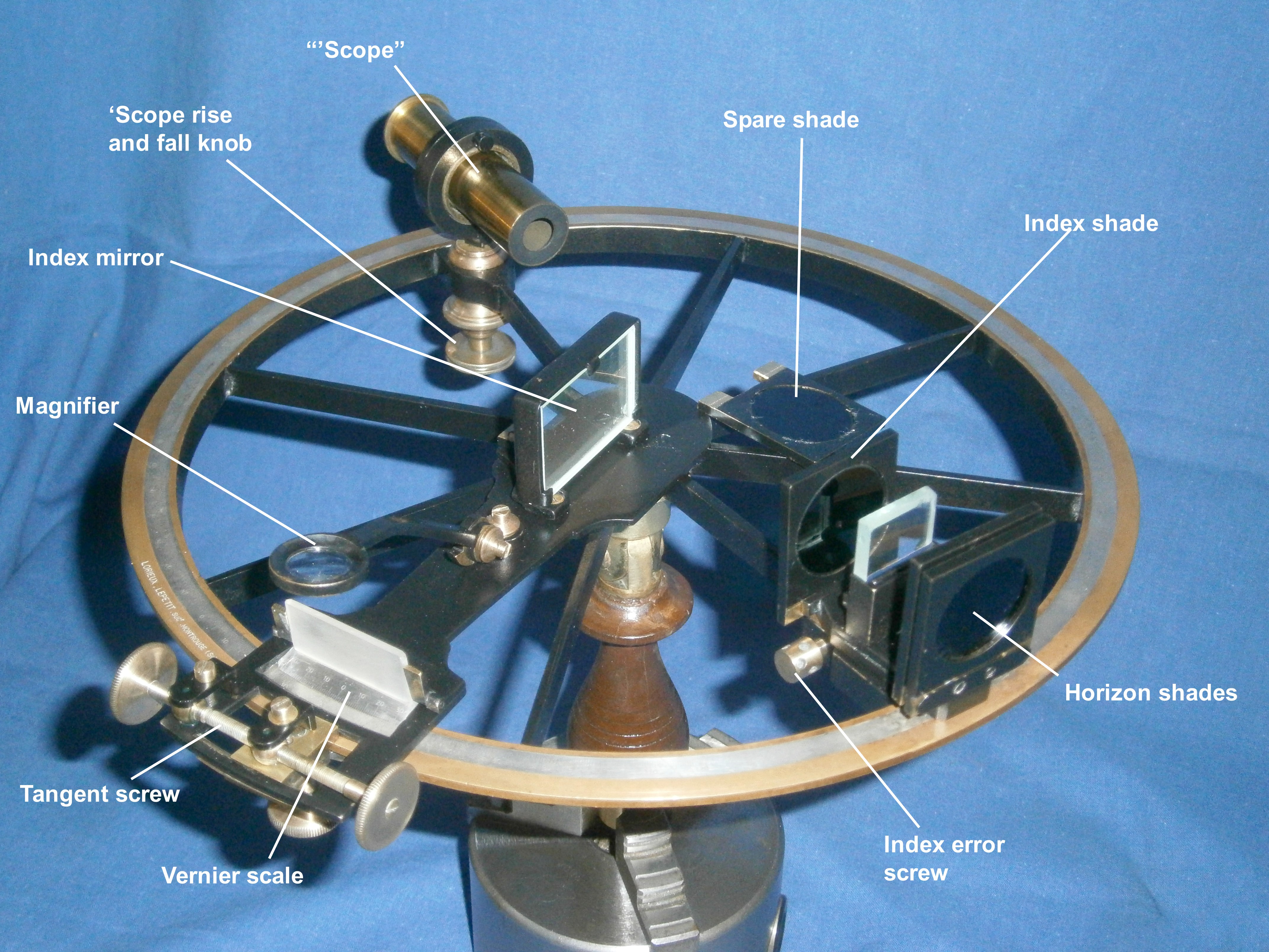


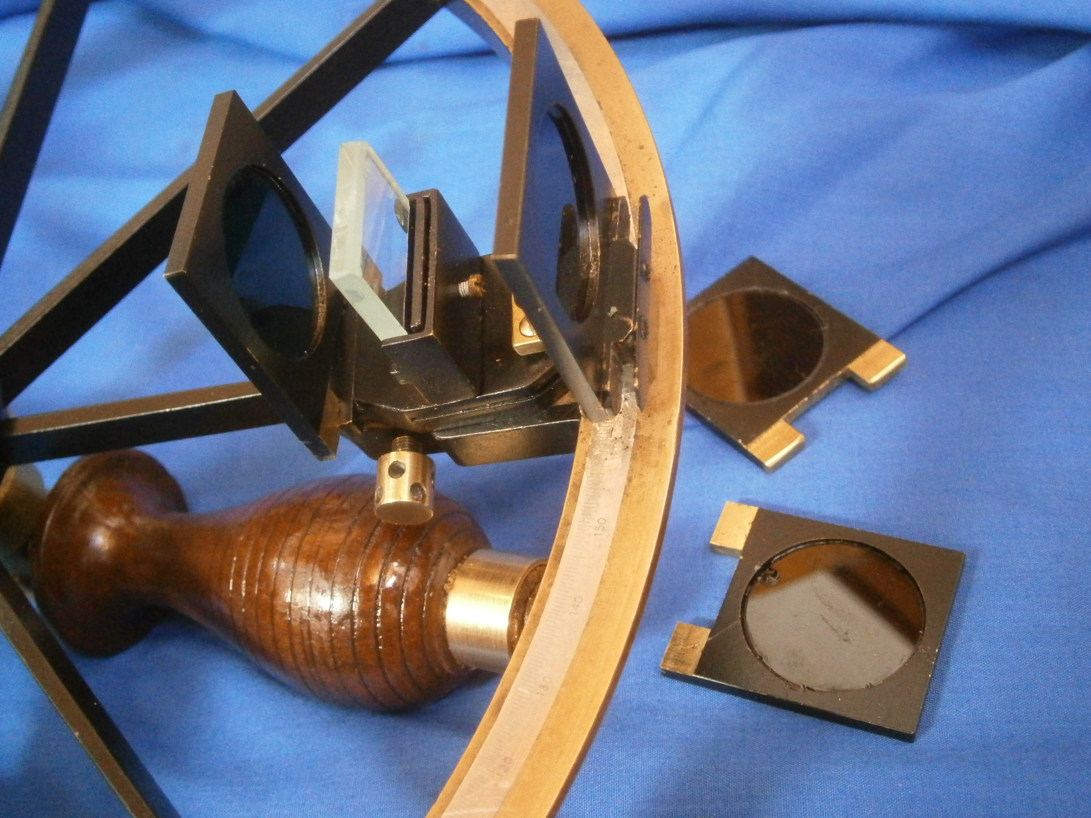

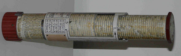
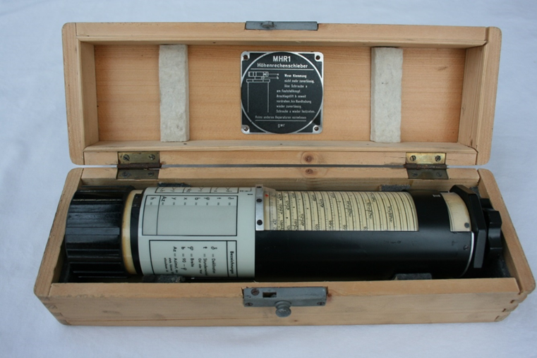

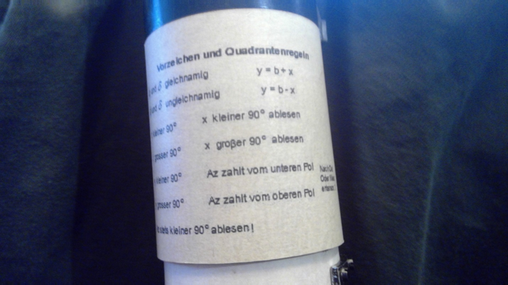

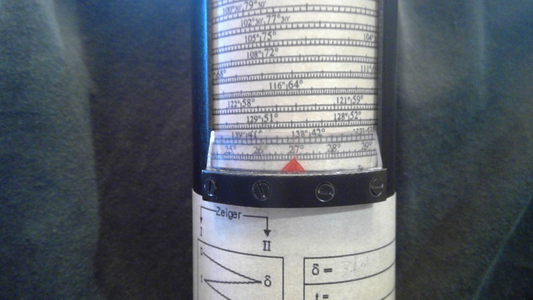

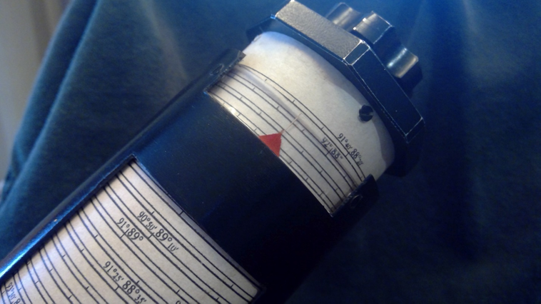


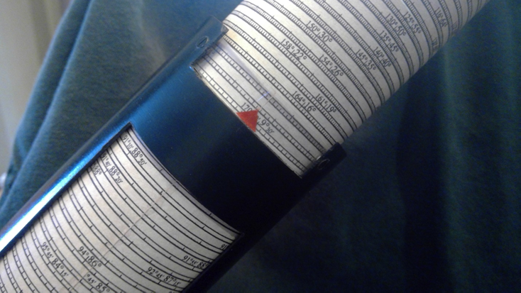
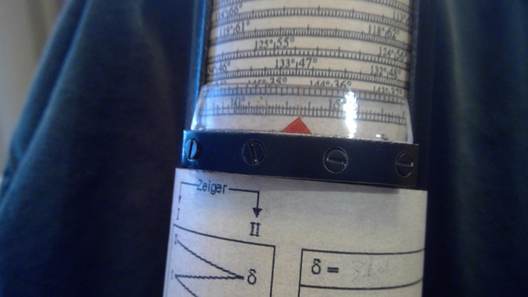
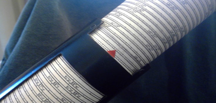


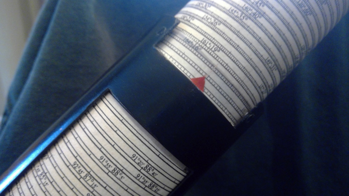

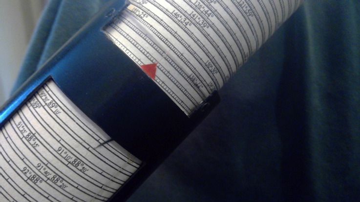
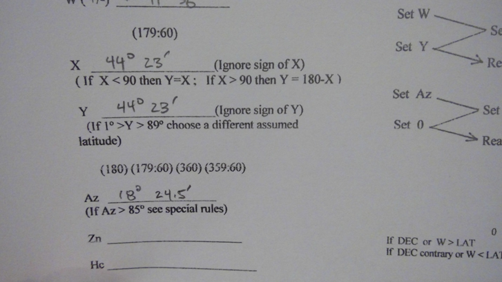


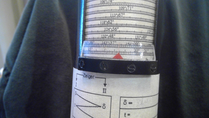


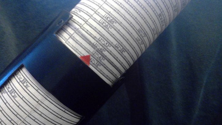
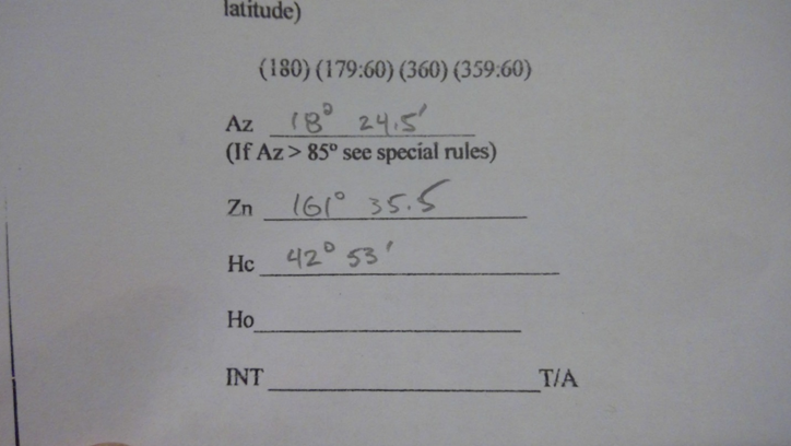

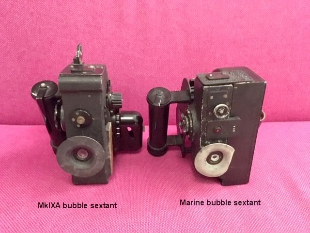
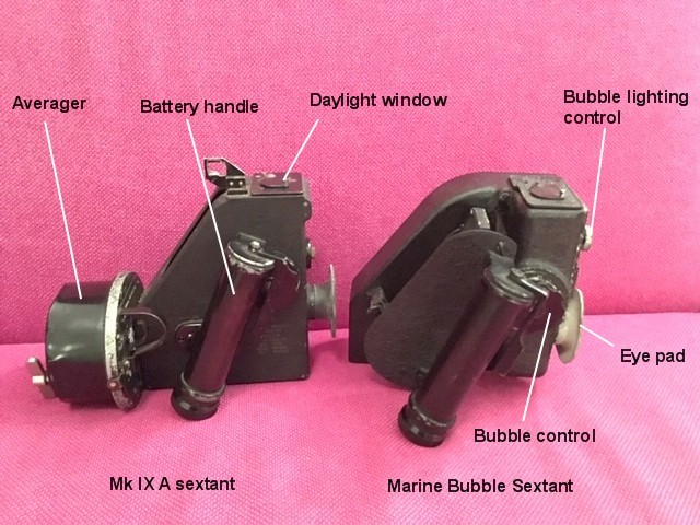
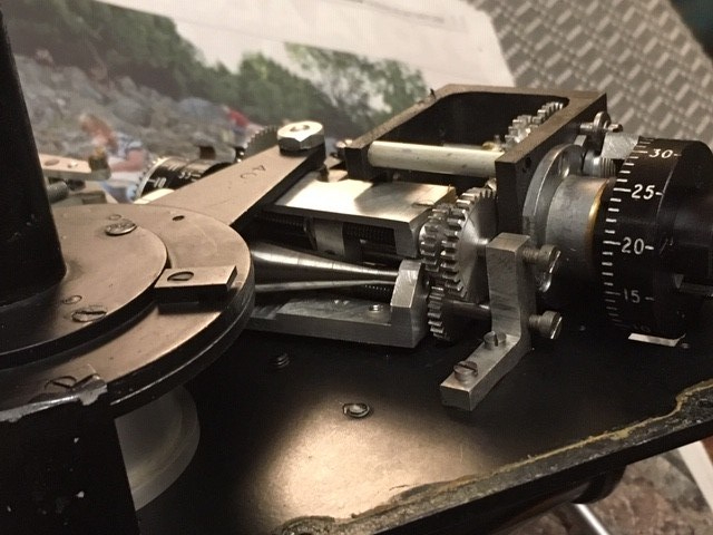
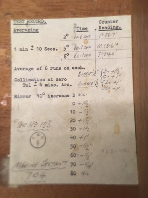
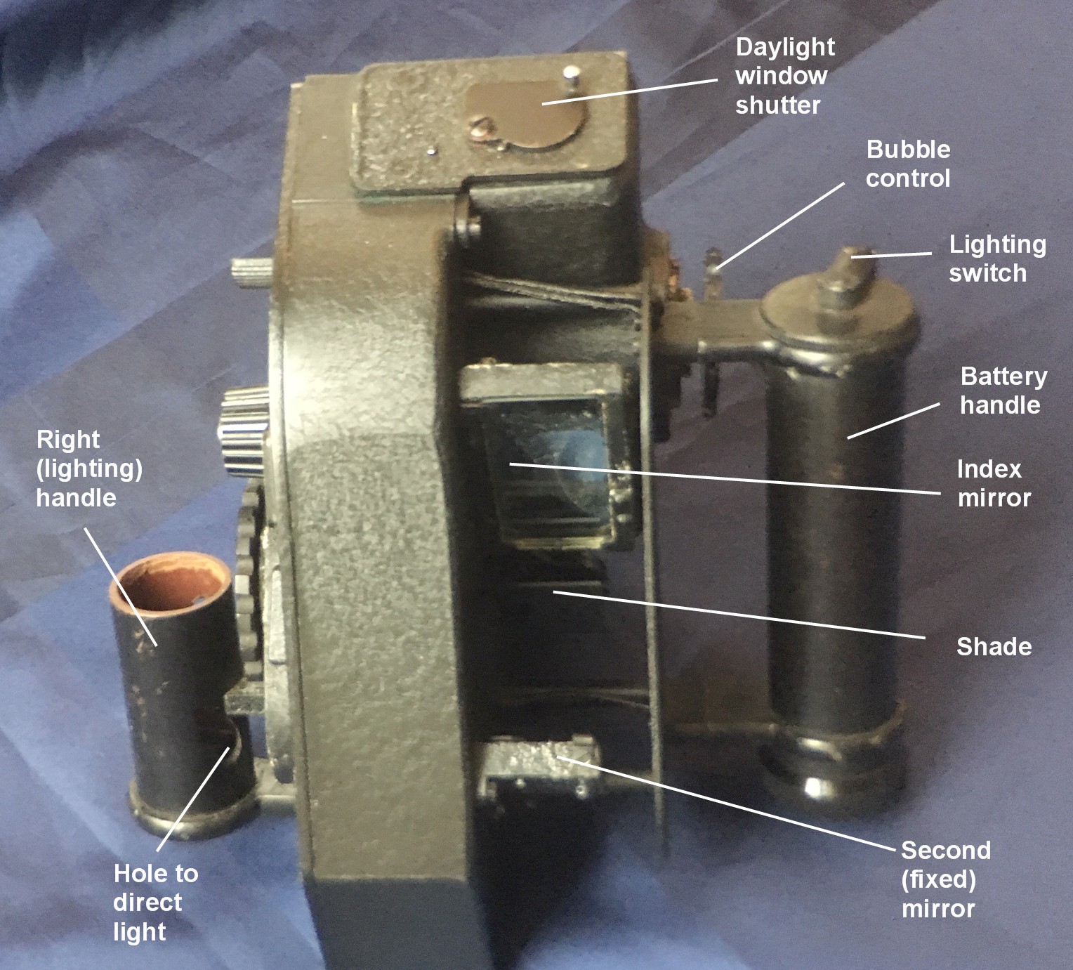
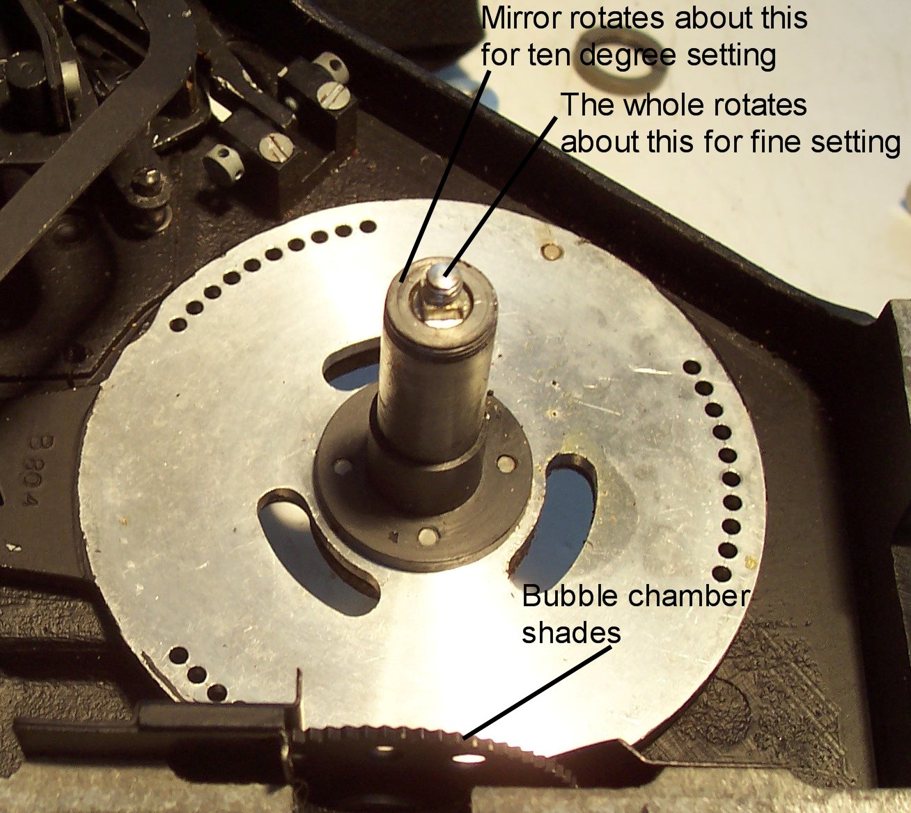
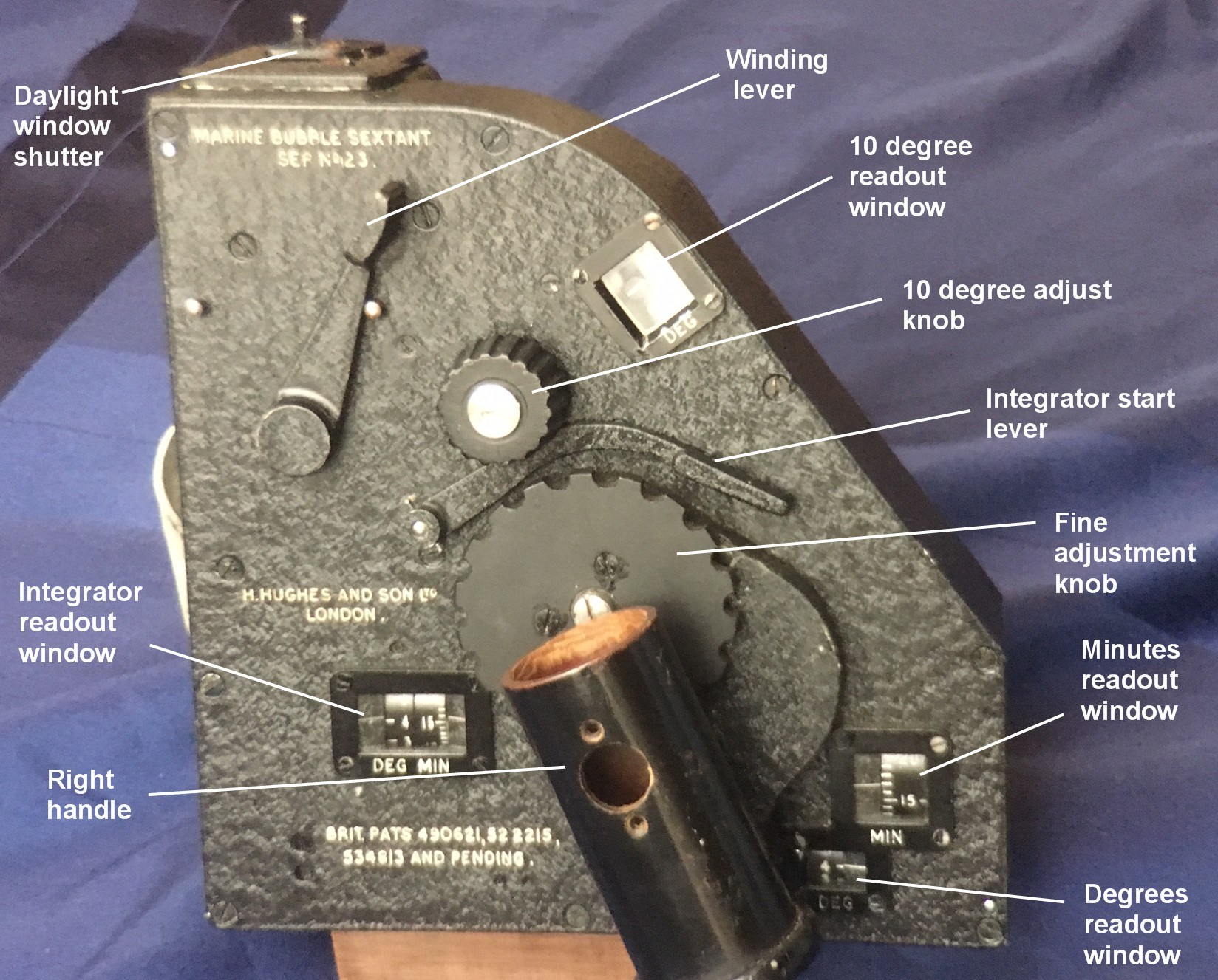
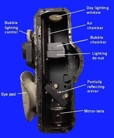
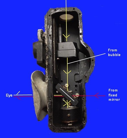
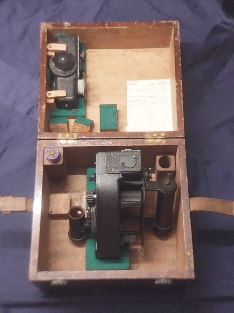


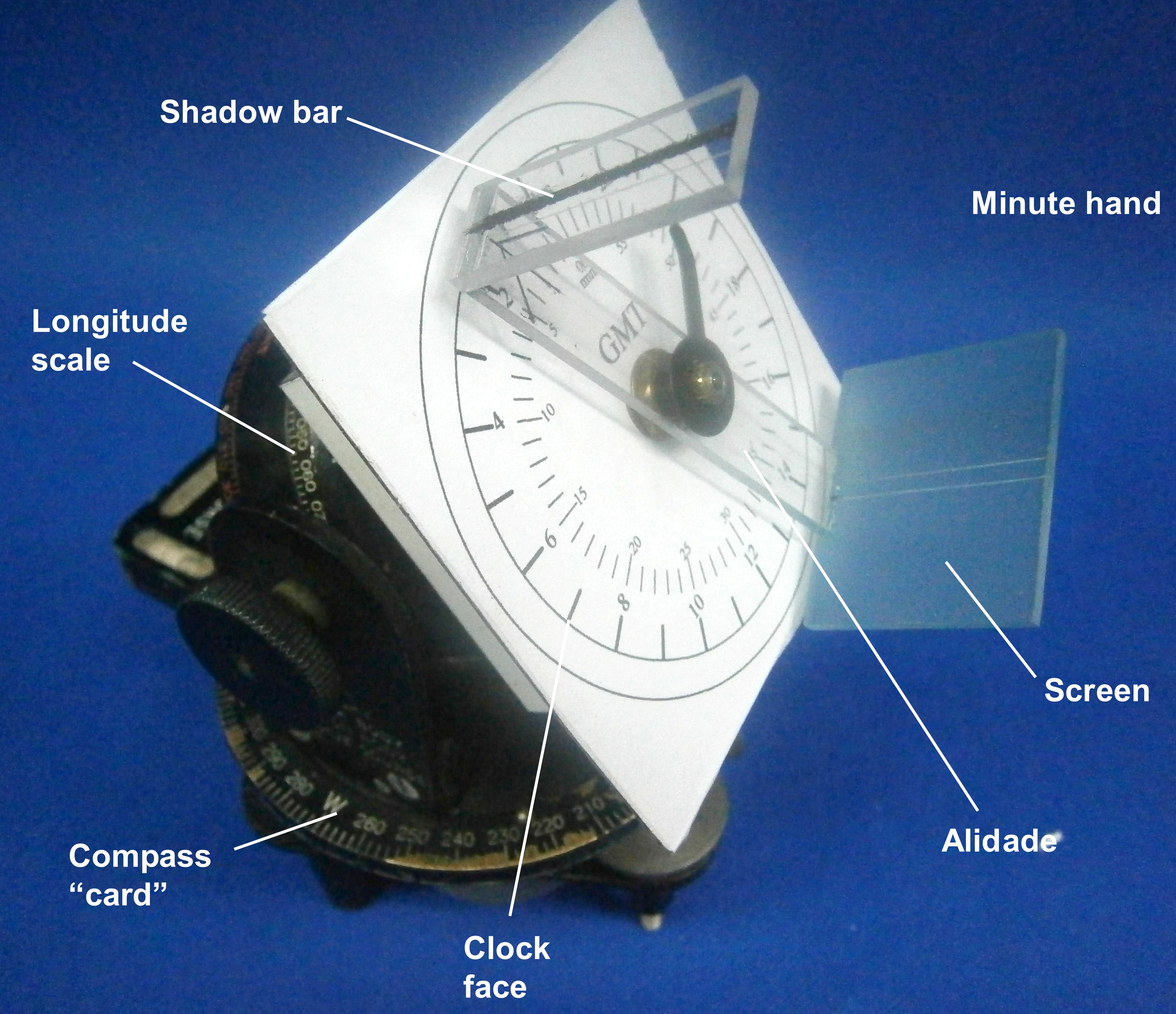

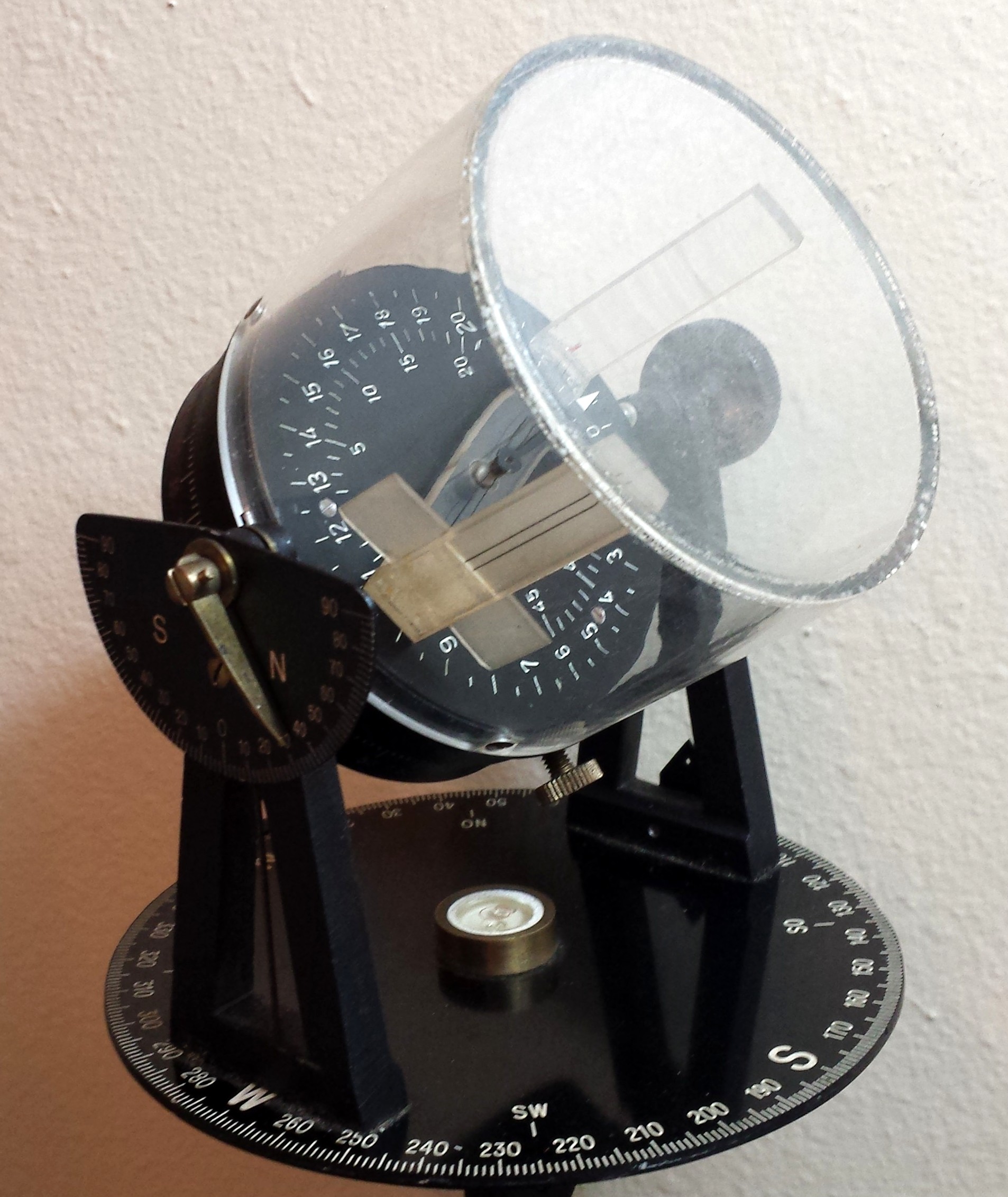
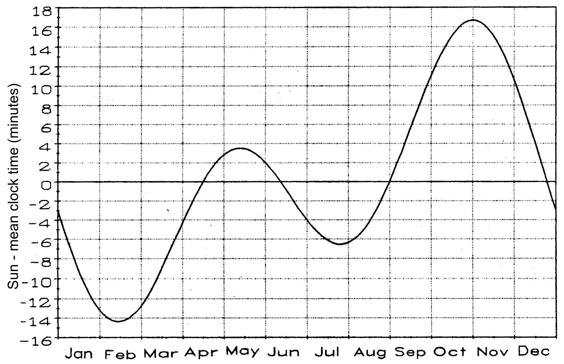
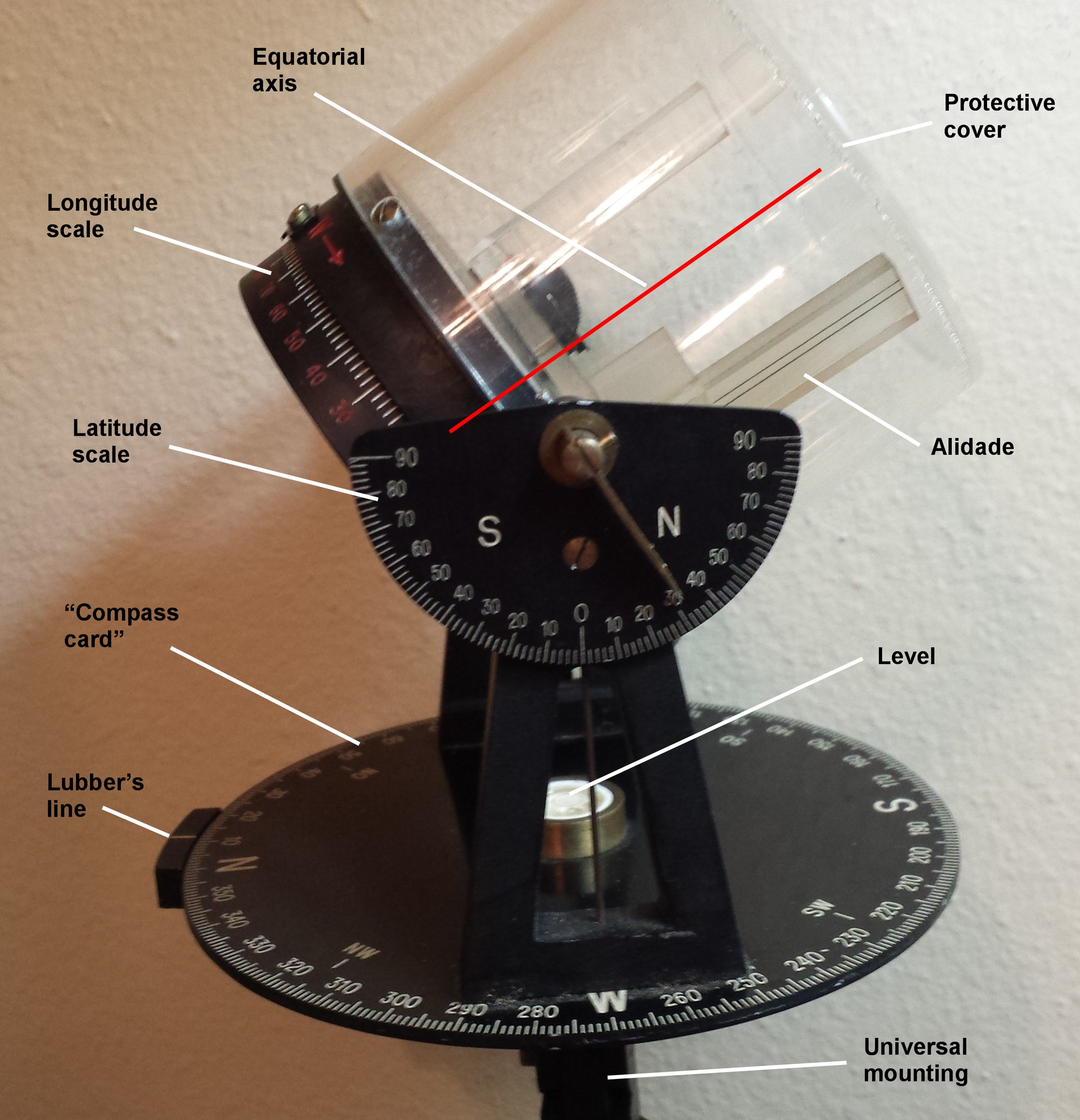
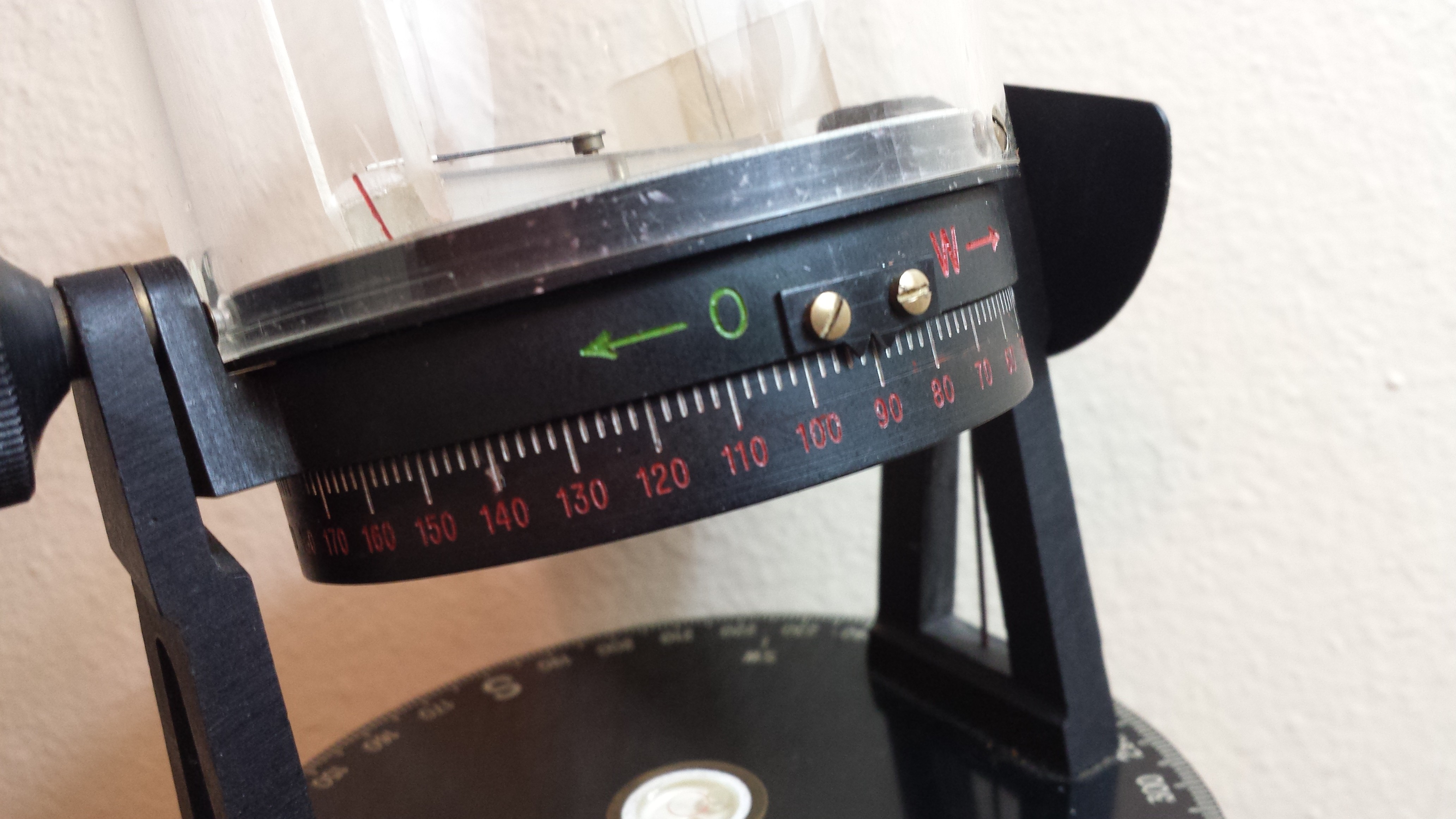

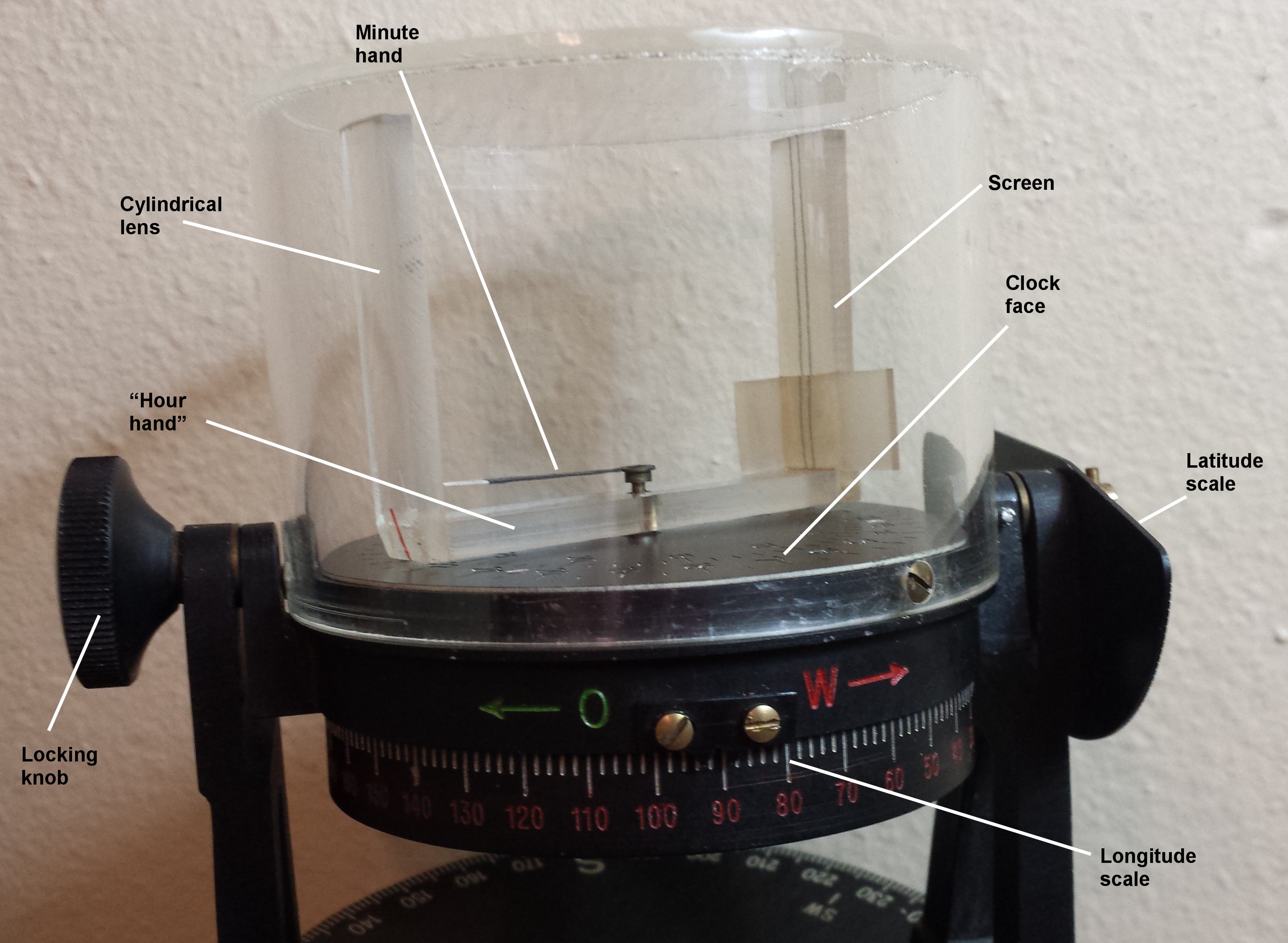
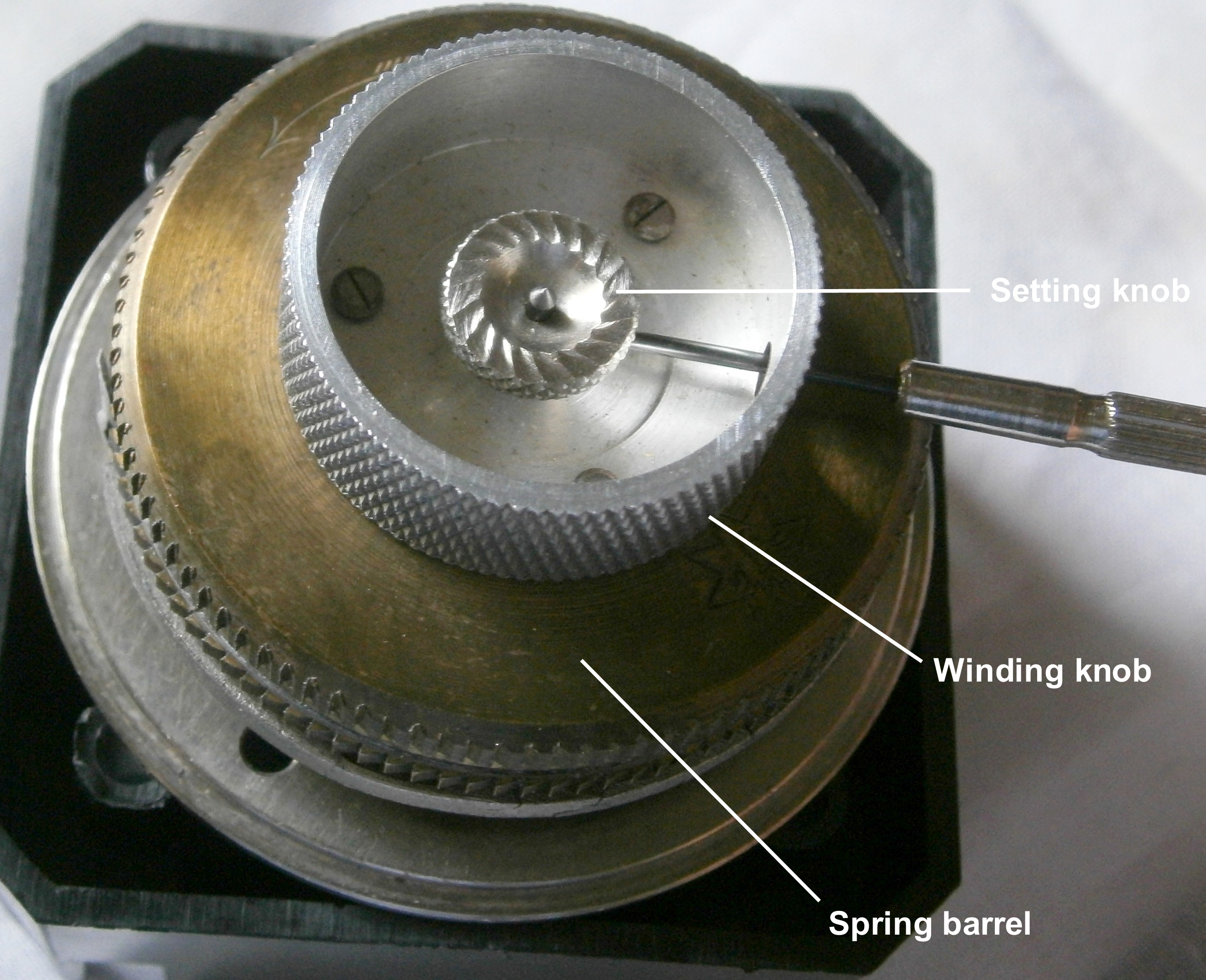

 view)")


You must be logged in to post a comment.