This post also appears under the category “Box sextants”. All figures may enlarged by clicking on them. Use the back arrow to return to the text.
Francis Barker, born in 1819, flourished in Clerkenwell Road, London from about 1840 until his death from tuberculosis in 1875. He was succeeded by his sons and the firm continued under his name until about 1932, when it was taken over, eventually by Pyser CGI of Edenbridge, Kent. Barker’s main products were magnetic compasses and sundials, though they did branch out into jewellery making in the late nineteenth century. Magnetic marching compasses continue to be made under the Francis Barker name. Probably in the second half of the 1970s they began to produce a yachting sextant and production probably continued for about ten years. Celestaire bought the entire remaining stock of 36 instruments in the late 1980s and disposed of all of them. They are relatively rare.
The sextant was a box or drum sextant and was contained in a heavy saddle leather case, retained by two press studs (Figure 1). It is quite difficult to extract it from its case without pulling on the strap and putting its stitching at risk. The small handbook reommends putting the strap around the user’s neck to guard against accidentally dropping it overboard.
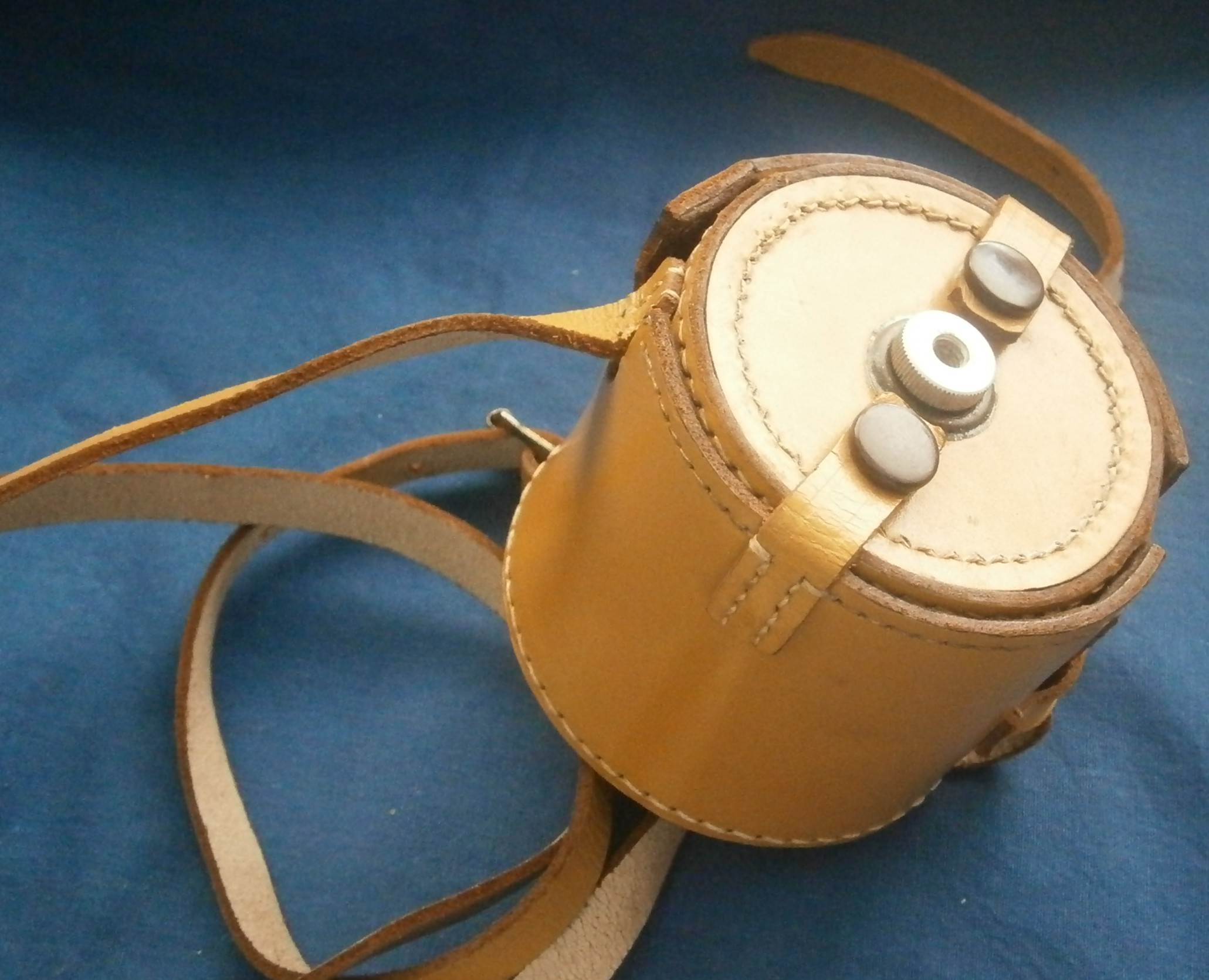
Figure 1. Sextant in its case.
Figure 2 shows the instrument out of its case, and Figure 3 shows the general arrangement with the principal parts labelled.

Figure 2: Sextant out of its case.

Figure 3: General arrangement.
The operating parts are contained within a light alloy drum 76 mm in diameter and 50 mm high. The main scale, 45 mm in radius, is divided to half degrees, and there is a vernier divided to single minutes. The setting knob contains a planetry drive, which gives a slow motion when rotated slowly and a fast motion when rotated more quickly.
There are two interchangeable peep sights (Figure 4), each with a 1.5 mm in diameter hole. One is provided with a shade for use when the horizon is bright. Many older users may have small central cataracts in their eyes and they may find that the hole in the sight is small enough to cause a shadow of their cataracts to partially obscure their view, in which case there is nothing to be lost by opening out the hole to, say, 2 mm, to allow more peripheral rays to by-pass the cataract. The two levers shown bring index shades into the light path.
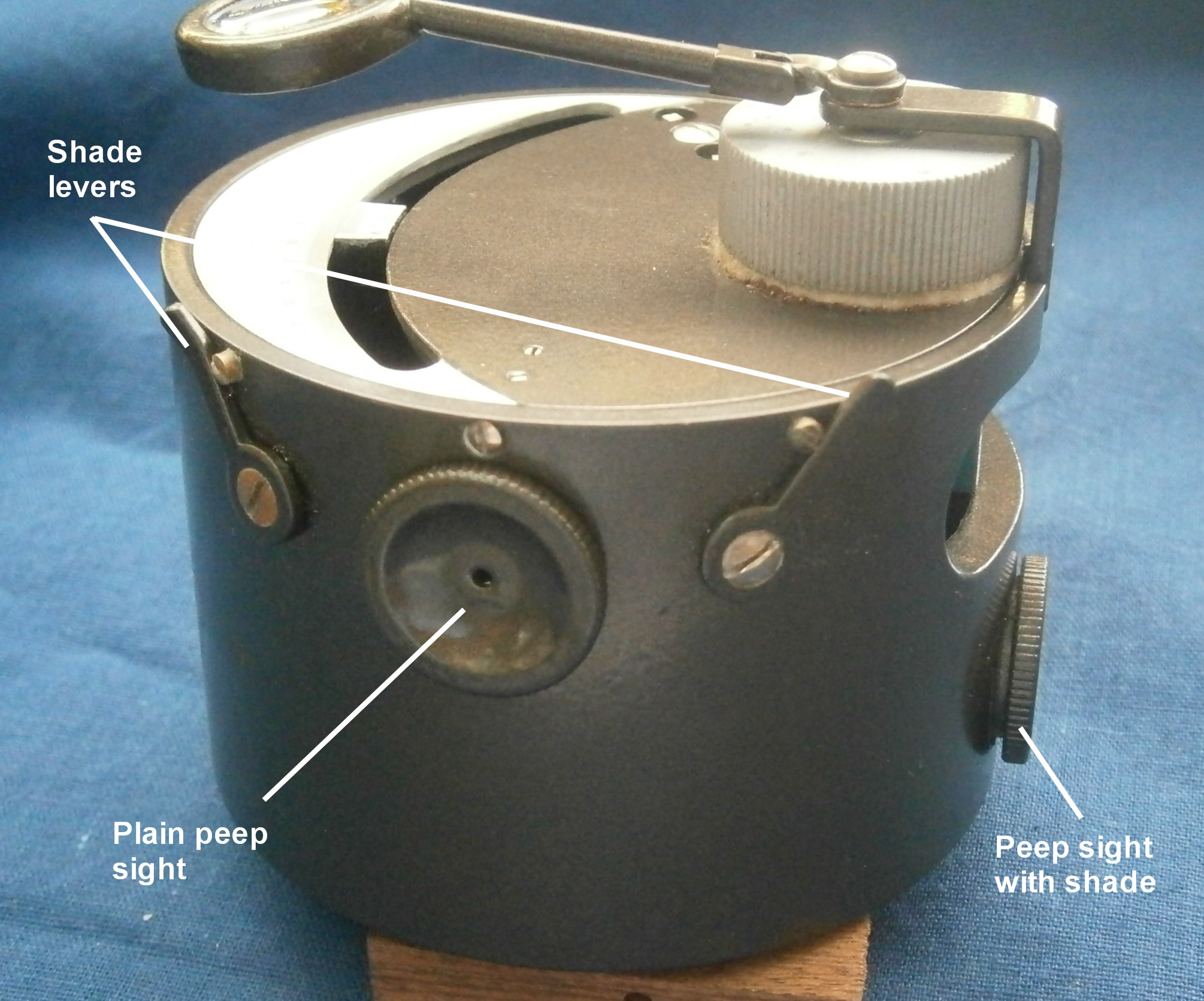
Figure 4: Peep sights and shades.
The internal arrangement for these shades is shown in Figure 5. According to Ken Gebhart of Celestaire, there are at least 18 units in ciculation in which full glasses were installed by mistake, instead of the half-glasses shown.

Figure 5: Horizon shades.
Figure 6 shows the general internal arrangement.

Figure 6; General internal arrangement.
The index mirror is adjusted for perpendicularity by the usual method (Figure 7) and Figure 8 shows how the mirror bracket is tilted by means of opposed screws which rock it about a horizontal axis formed by the heads of two grub screws.
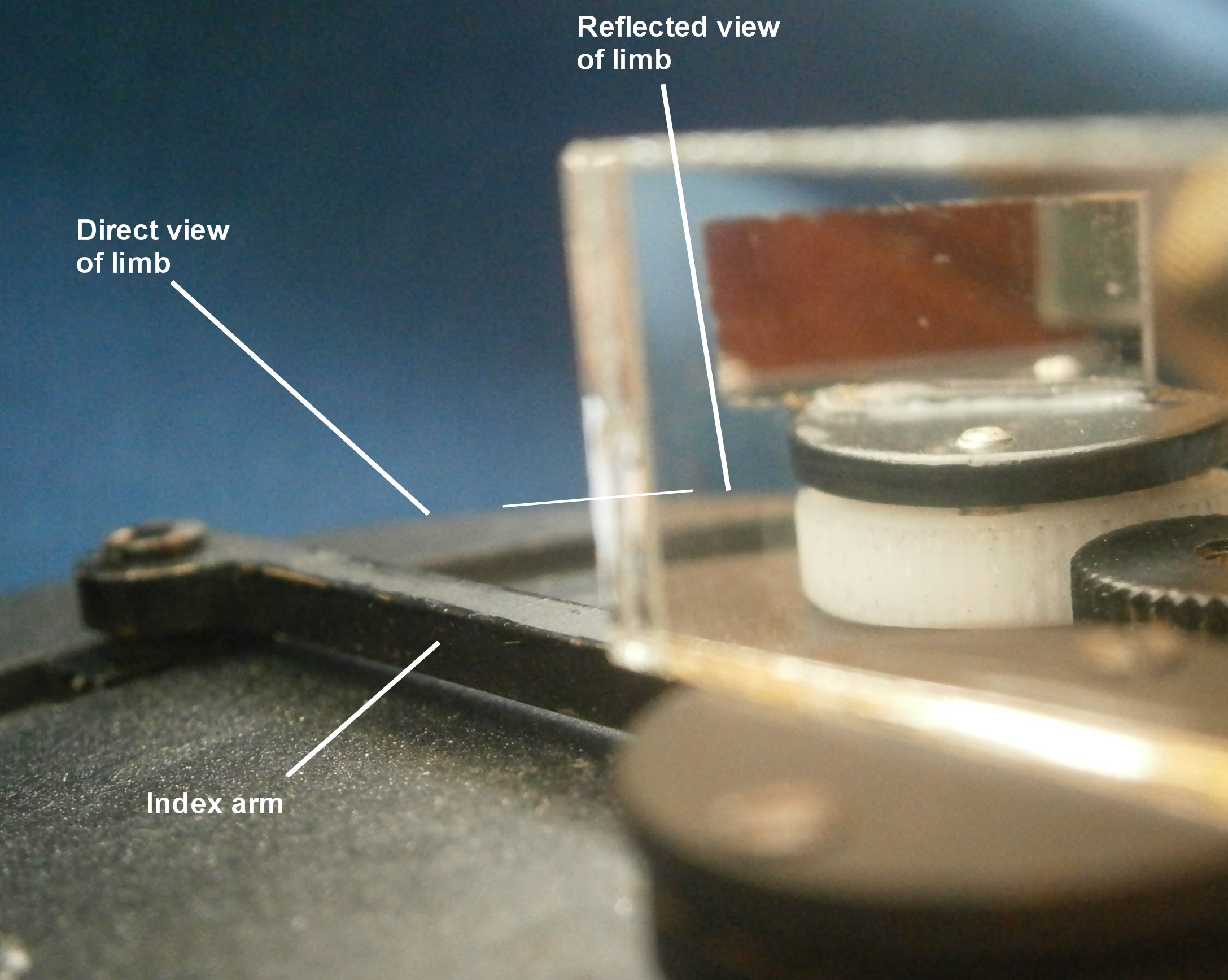
Figure 7: Aligning index mirror for perpendicularity.

Figure 8: Index mirror mounting and adjustments.
The method of adjusting the horizon mirror for index error can be seen reflected in the index mirror in Figure 7 and a close up is shown in Figure 9. Side error is taken care of by the same method of rocking about an axis by two opposed screws , while index error is removed by rotating the whole mirror bracket via a metal gear meshing with a nylon gear.
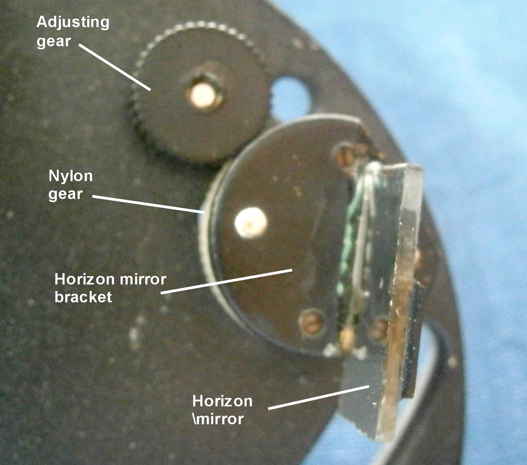
Figure 9: Horizon mirror adjustments.
The squared heads of the adjusting screws are on the face of the sextant and are adjusted by means of a key that unscrews from its nearby housing (Figure 10). The slotted screw must be tightened before removing side error and then slackened off a little to allow adjustment for index error. This may introduce some more side error, so the cycle may need to be repeated a few times, after which the slotted screw is carefully re-tightened.

Figure 10: Heads of adjusting screws
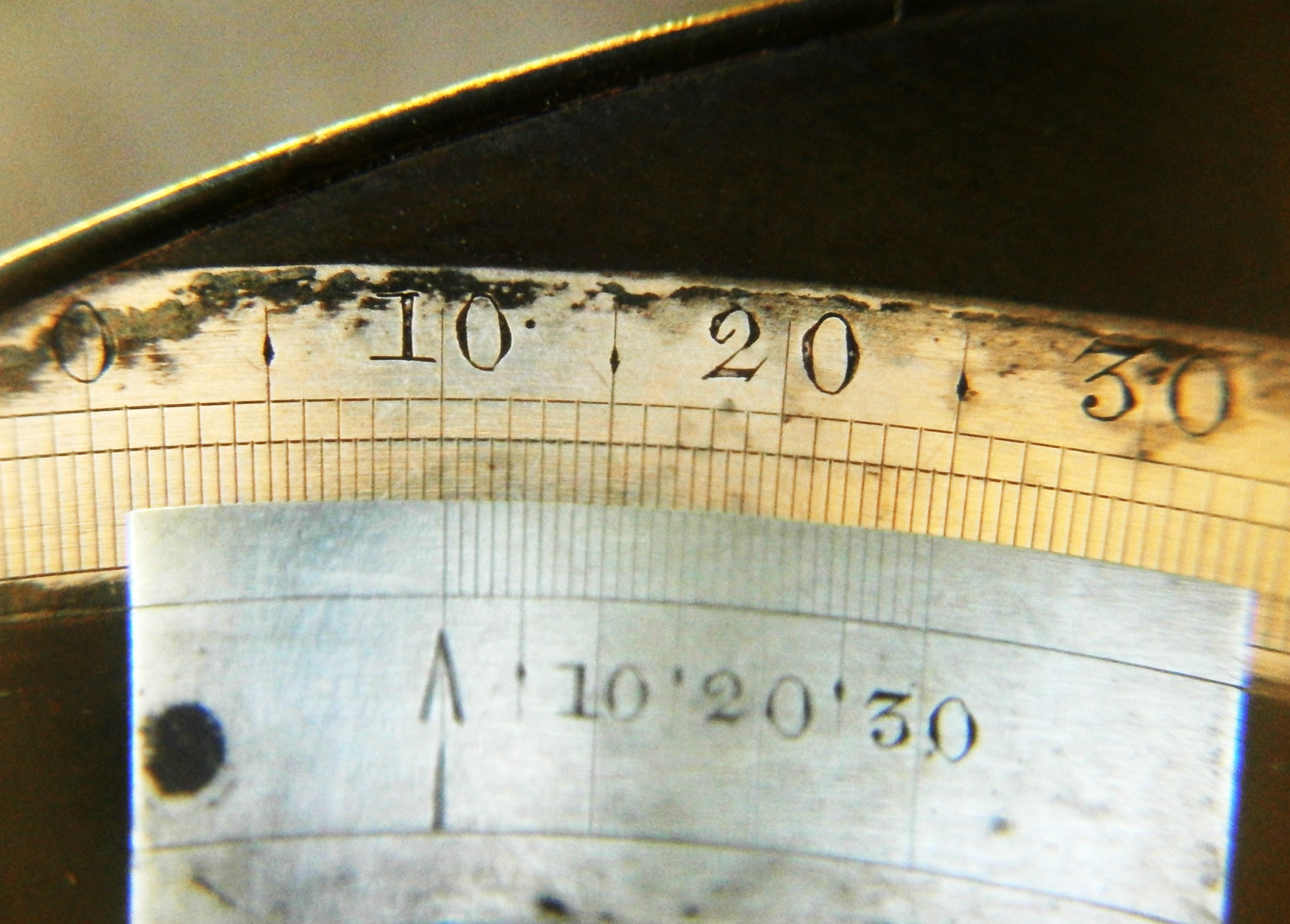
The scales are read with the help of a plano-convex lens of about 25 mm focal length (Figure 11). The divisions lack a little of the crispness seen in earlier box sextants. The rather small radius of the arc, of 45 mm as opposed to about 160 mm for a full size vernier sextant, makes deciding which line on the vernier coincides with a line on the main scale somewhat problematical. In the photograph, which gives a fair representation of what is actually seen, at least three lines coincide, so perhaps the best that can be done is to decide which two pairs just do not coincide and to chose the lines midway between the two pairs.
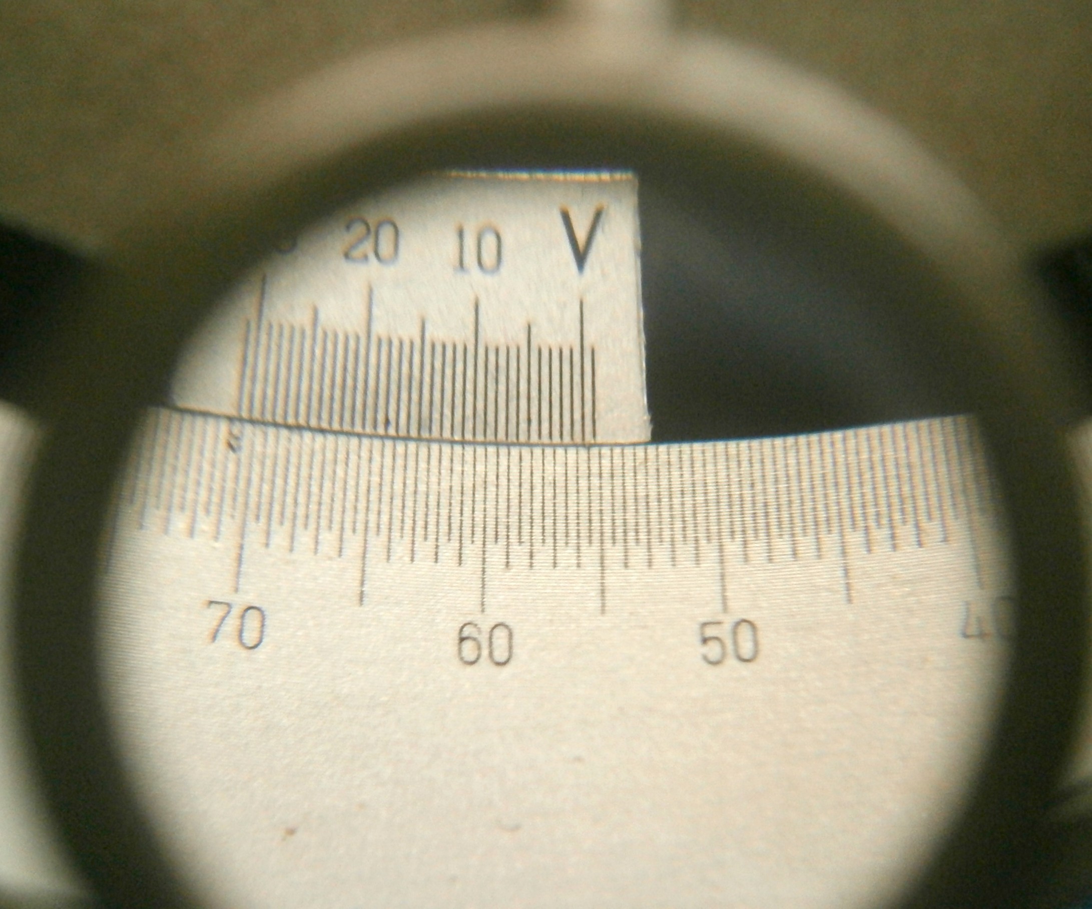
Figure 1. Sextant in its case.
If you enjoyed reading this post, you may also enjoy my books “The Nautical Sextant” and “The Mariner’s Chronometer” (www.chronometerbook.com).
.


You must be logged in to post a comment.