This post is preceded by “How to Refill C Plath Bubble Artificial Horizon”; “The SOLD KM2 Bubble Sextant”; “C Plath Bubble Horizon Attachment”;“A gummed up AN5851-1 averager”, “Bubble illumination of Mk V and AN 5851 bubble sextants” , ”Refilling Mark V/AN5851 bubble chambers” , ”Overhaul of MkV/An5851 bubble chamber” , ”AN5851-1 : jammed shades carrousel” , ”A Byrd sextant restored” , ”Update on Byrd Aircraft Sextant”, “A nautical sextant bubble horizon” and “Sealing A10 vapour pressure bubble chambers.”
All Figures may be enlarged by clicking on them. Return to the post by using the back arrow at top left.
Brief history
In 1922, Gago Coutinho, a Portugese naval aviator and inventor, was the first to fly the Atlantic, from Lisbon to Rio de Janeiro via the Las Palmas and Fernando Norohna using celestial navigation. According to A J Hughes, he descended to low levels to use the natural horizon and it is not clear whether he used an artificial horizon instrument of his own design, adapted from one by C Plath, but at any rate, he took such an instrument with him. As Figure 1 shows, this historic instrument was a vernier sextant fitted with an artificial horizon in the form of a longitudinal level vial and with scale illumination
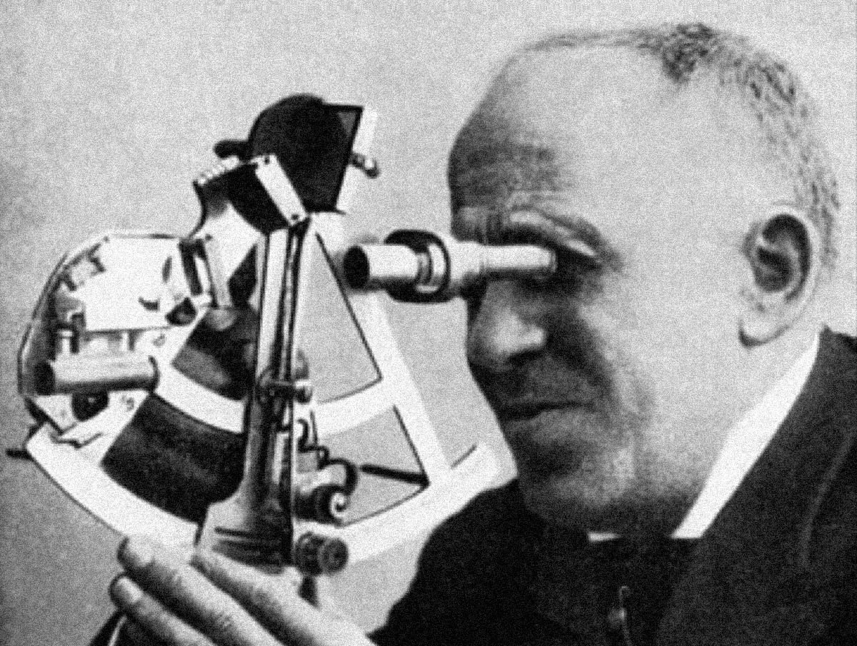
Figure 1: Admiral Coutinho using his early bubble sextant.
With the cooperation of C Plath, the sextant was further developed at the request of the Portugeuse Navy and by 1927 had reached the final form which is often illustrated in histories of air navigation. Captain Wittenman navigated the Graf Zeppelin around the world in 1929 using such a sextant.The sextant was shown at the 1930 Berlin Airshow and was apparently popular with airlines in the 1930s. It is said that Henry Hughes and Son were also asked to develop the design but showed little interest. Their gifted chief designer, P F Everitt was developing Hughes’s own sextant, which evolved into the versatile Mark IX bubble sextant series. During the Second World War, the Japanese navy used a version of the fully developed sextant. Whether it was simply an exact copy of the Plath version by Tamaya, with better developed scale lighting, or whether it was in fact a Plath instrument with Japanese markings will probably never be known, but the Japanese certainly had a highly developed engineering and instrument industry, as many Western engineering firms and instrument makers learned to their cost after the war.
General
A little while ago, I acquired such a copy, shown in its case in Figure 2 and, with its accessories, out of the case in Figure 3. It appears to be the fifth in a group of five and has naval markings.
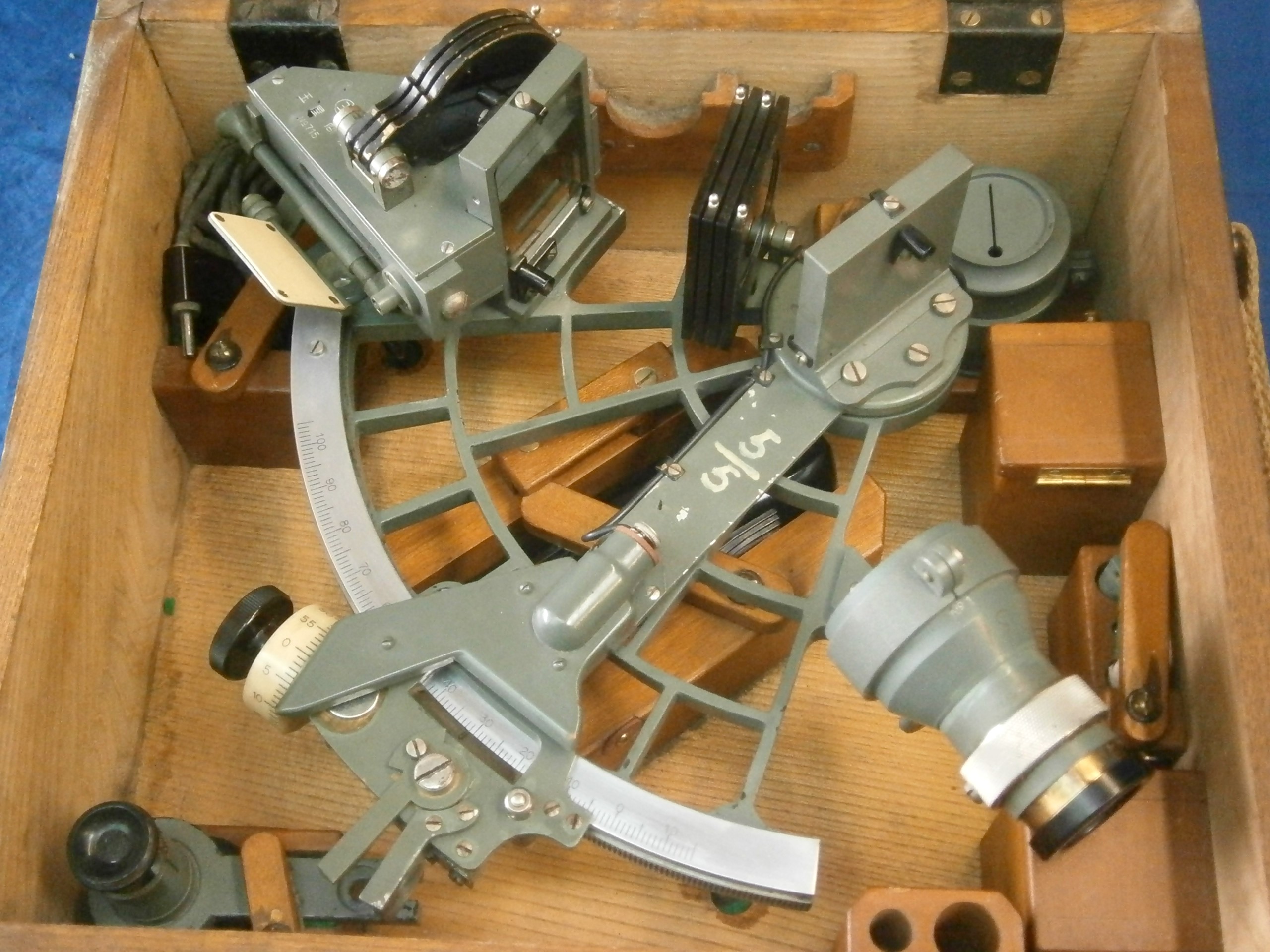
Figure 2: Coutinho pattern sextant in its case.

Figure 3: Contents of case.
The sextant differs from C Plath’s standard ladder pattern micrometer sextant in several aspects. The most obvious is the artificial horizon, and to accommodate this and also allow its use with the natural horizon, the index mirror is unusually tall (see Figure 8). The frame is of aluminium alloy, something that Tamaya in particular developed post-war when combined with a bronze rack, and the scale reads from – 15 degrees to 105 degrees. There was obviously no need for the scale to read beyond 90 degrees and it is possible that the unusually wide negative range of -15 degrees was intended to be used to determine the distance off known objects from the air, provided that the height of the aircraft was known. The design of the artificial horizon requires a special telescope in addition to a standard telescope; and two peep sights are also provided. Tamaya was probably the first to use a perspex light guide to illuminate the main scales and provision also had to be made to light the artificial horizon.
The artificial horizon system
Figure 4 shows the horizon mirror. Rays from the over-size index mirror are reflected off the silvered portion into the eye via a telescope or peep sight, while the natural horizon may be viewed in the usual way through the clear portion, using shades if necessary. When using the artificial horizon, the shades are all folded over to obscure the clear glass.
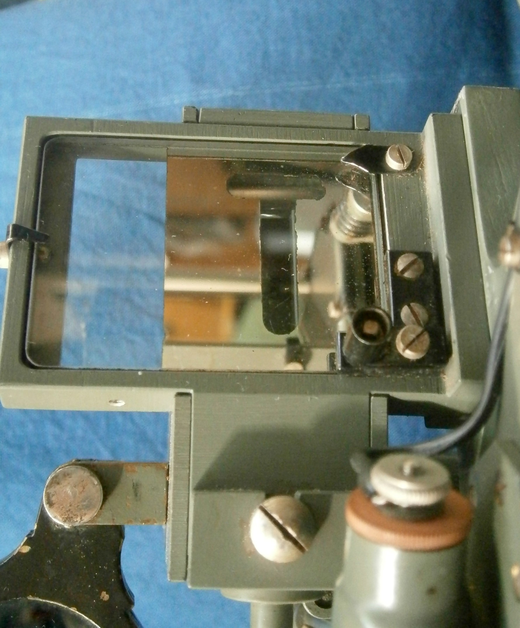
Figure 4: Face of horizon mirror.
In use, the longitudinal spirit level is viewed through the upright of the T-shaped gap in the silvering by reflection off a mirror and the tilt level vial is viewed directly via the cross piece of the gap to ensure that the frame of the sextant is vertical (Figure 5).

Figure 5: General arrangement of interior of artificial horizon.
The longitudinal vial is illuminated from below through a slot in the casing, using a white diffuse reflector by day and a bulb let into the frame by night. The tilt level seems to have been left to take its chances, as it is a little hard to discern by day and more so by night.The purpose of the blank shade whose axis is seen directly above the reflector is unclear. It was probably intended to reduce stray light at night from the bulb.
Figure 6 shows the tilt or cross vial in more detail.. It also shows the counter spring for the index error adjustment which must necessarily be made from the front of the mirror rather than, more usually, the back.

Figure 6: Detail of cross vial.
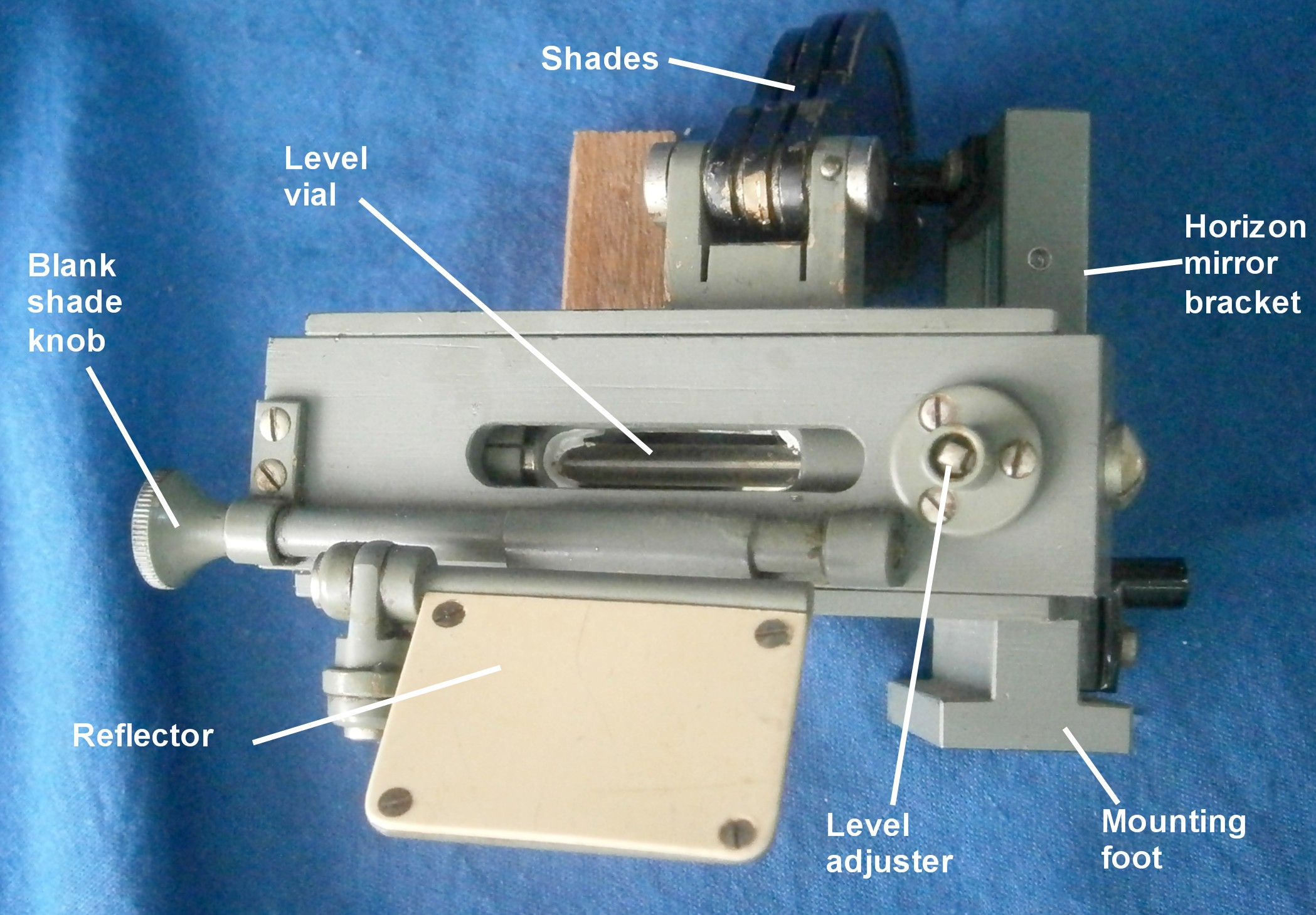
Figure 7: Artificial horizon from below.
A spare cross vial and two longitudinal vials in their carriers were provided and this enabled me to check an essential requirement of a bubble sextant: that once the bubble and the image of the observed body are brought into coincidence, they move together when the sextant is tilted fore and aft. For this to happen in most bubble sextants, the bubble is at the focus of a collimating lens, so that an image of the bubble appears at infinity when combined with a view of the object in a beam splitter. The radius of curvature of the vial must be the same as the focal length of the collimating lens. In the Coutinho sextant, that translates into saying that the working distance of the lens that sees the bubble and the radius of the vial must be the same.
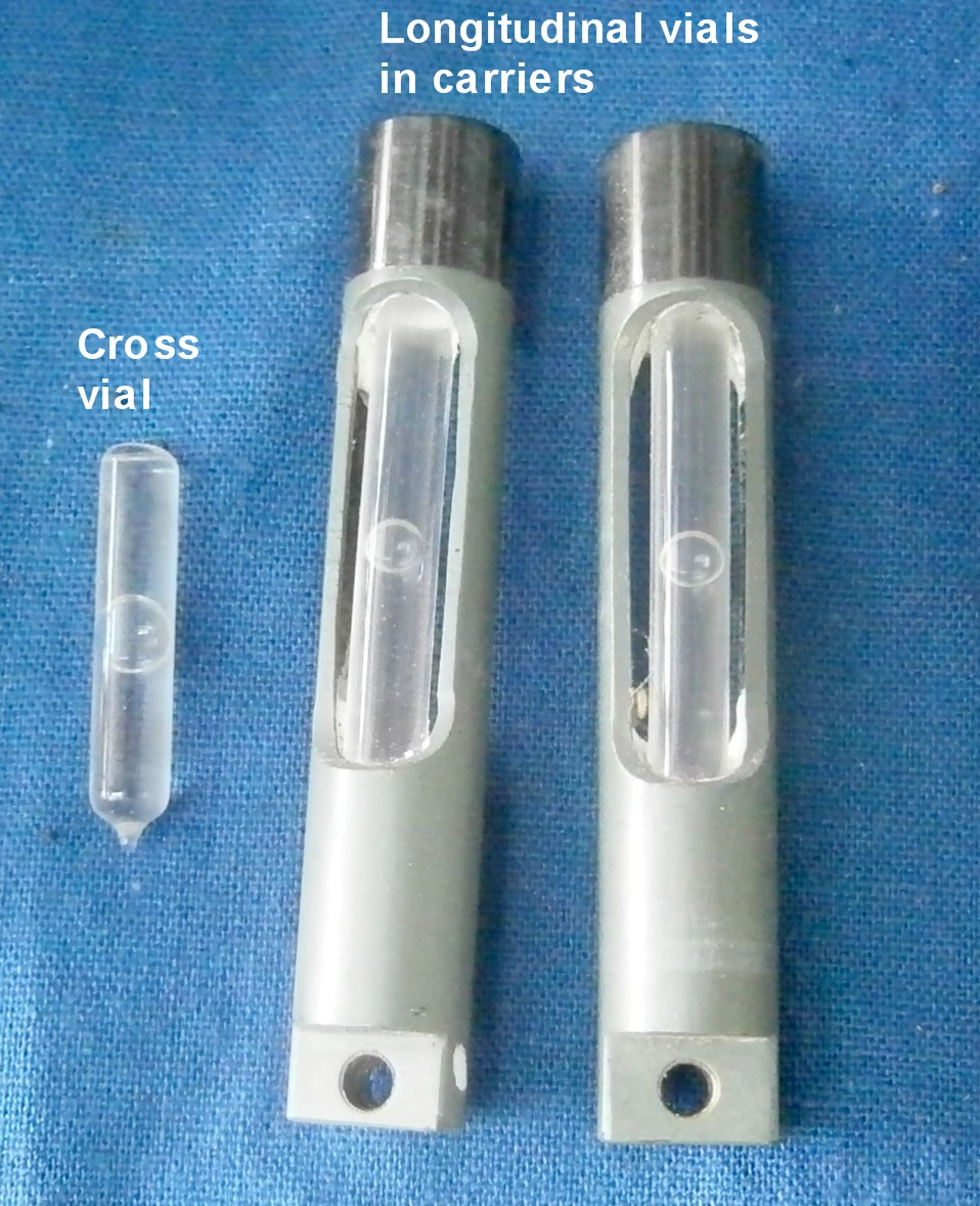
Figure 8: Kit of spare vials.
In 2001, when I was investigating how to grind sensitive spirit level vials, I made a version of the National Physical Laboratory small angle generator (described in On the Level. Model Engineers’ Workshop, October 2001). With it, I measured the sensitivity of a vial and found that the bubble moved 5 mm for a change in angle of 0.024 radians (1.389 °). Thus the radius of the interior of the vial is 5/0.024 ≅ 208 mm, and this corresponds roughly with the distance between the objective lens and the vial via the mirror, given that it is not possible easily to determine where in the lens system to measure from (see below).
Figure 9 shows the unusually large index mirror with the horizon mirror reflected in it.It is about 45 mm square, so that the mirror is tall enough for the instrument to be used with both artificial and natural horizon. C Plath and Japanese sextants that followed their practice were using large mirrors and objective lenses at a time when British, French and American sextants lagged well behind. To make an extreme comparison, the war-time standard C Plath sextant had an index mirror 56 x 42 mm (2352 mm²), a horizon mirror 55 mm in diameter with a silvered area of 2375 mm² and a telescope objective diameter of 40 mm (1256 mm²), while the Mark II US navy sextant had an index mirror 40 mm square (1600 mm²), a rectangular horizon mirror with a silvered area of 325 mm² and a telescope objective of only 18 mm diameter (255 mm²).
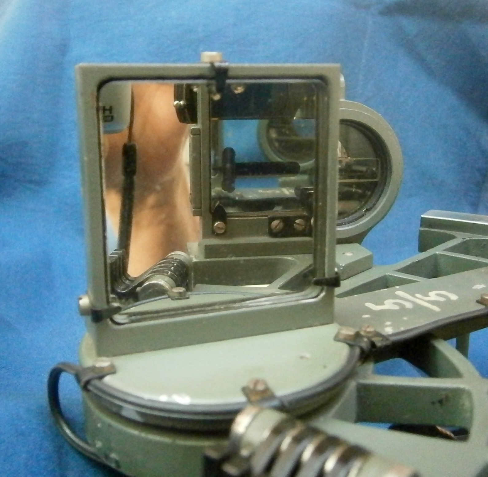
Figure 9: Index and horizon mirrors.
Telescopes and sights
Three sighting devices were provided: a standard 3 x 30 mm Galilean or star telescope with an extra long rising piece to bring it in range of the clear part of the horizon mirror; a 2 x 34 mm telescope for use with the artificial horizon (AH) ; and a peep sight with interchangeable sights, one a simple 1 mm vertical slit and the other a 1 mm slit expanding to a round 4 mm hole at one end, for use with the artificial horizon. I will describe only the two latter.
Figure 10 shows the general arrangement of the AH telescope.The body is a heavy brass turning held in a stout brass rising piece. Focusing is done by rotating a knurled ring with a threaded peg which engages in a spiral slot cut into the wall of the eyepiece tube. The 12 mm diameter negative eye lens has a power of -21.25 dioptres or 47 mm, so we may take the focal length of the main objective lens to be about +95 mm (10.5D).

Figure 10: Telescope for use with artificial horizon.
The objective lens is combined with an auxiliary lens, selected so that when an object at infinity is viewed, the longitudinal bubble of the level is also in focus (Figure 11). As the combination has a focal length of about +70 mm (14D), we may deduce that the focal length of the auxiliary lens is about +280 mm (3.6D).
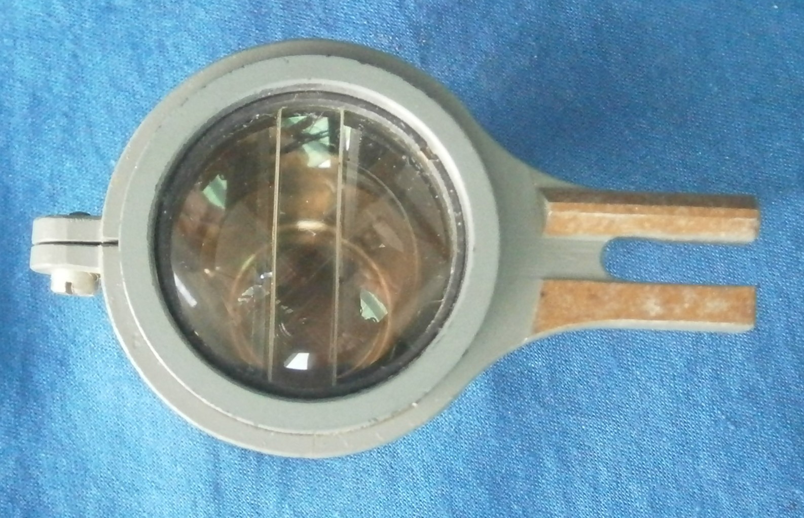
Figure 11 : Bubble sextant objective lens.
Figure 12 shows the objective lens exploded. A slice of auxiliary lens is cemented to a plane parallel glass and its convex side faces the convex side of the main objective lens, separated by a spacer ring. The whole combination is held in the body with a threaded retaining ring. At about the same time as this type of bubble sextant was conceived, Richard E Byrd, then a Lieutenant Commander in the US Navy, had constructed for him a sextant on the same principle, in which an auxiliary half lens allowed a single longitudinal vial to be viewed. There was no tilt vial. See my posts for 30 May, 2009 and 11 August 2009 for details of this sextant.
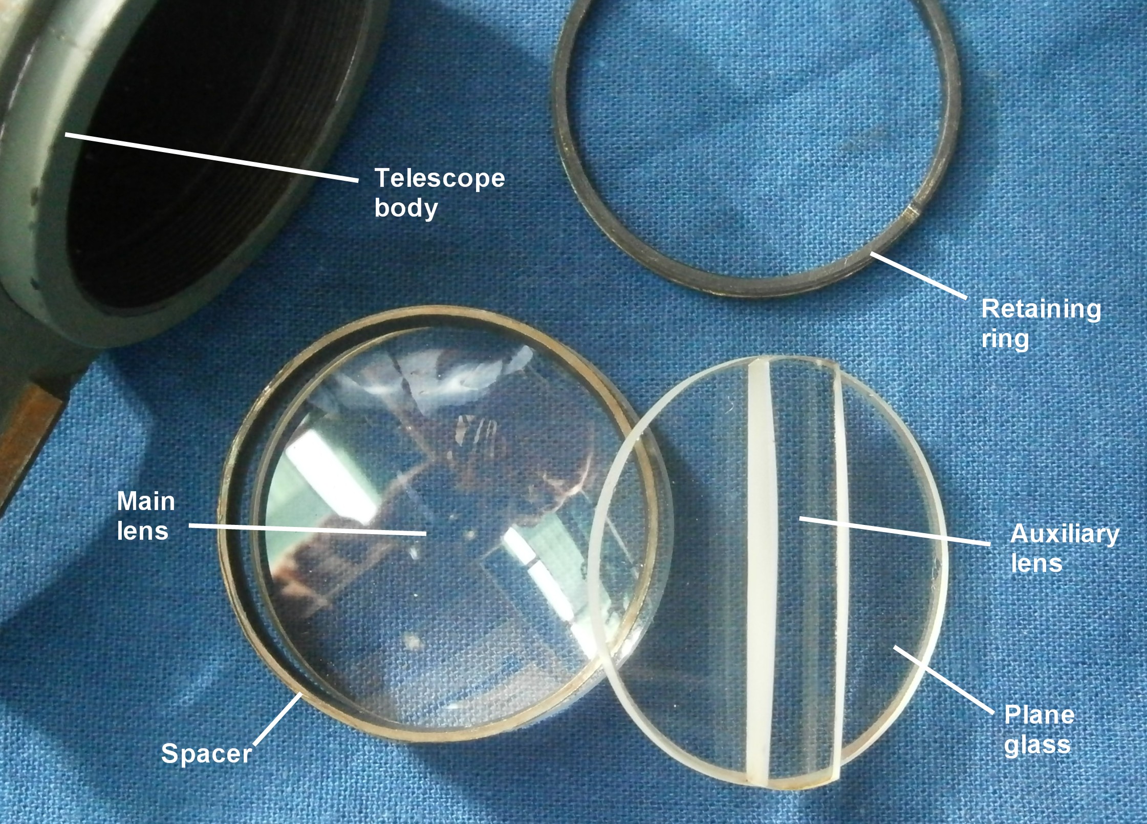
Figure 12 : Objective lens dissected.
When the objective lens of a Galilean telescope is, say, half covered, that half of the image disappears, whereas with a Keplerian telescope, the whole image remains but is of half the intensity. Thus, with this special telescope it is difficult to superimpose the image of the observed object upon the bubble (since the auxiliary lens places it well out of focus); it can however be placed alongside. By careful choice of the index shades and by moving the eye to one side of the field of view, it is possible to superimpose the images, presumably utilising reflection off the front face of the unsilvered “T”, but I cannot imagine that this would be easy in an aircraft A corollary of this is that the bubble of the tilt level is not quite in focus, being nearer to the objective that the other bubble. It is also poorly lit and on the extreme outside of the field of view, even out of view altogether for spectacle-wearers. I imagine that it would need considerable practice to get the two levels and the image of the observed body in the right places together. On land, I can achieve only fleeting coincidences with the sun. I will report later on star observations.
Withe the peep sights (Figure 13) matters are easier, as the slot increases the depth of field and everything is more or less in focus, while the image of the sun and the bubble are about the same size. The two apertures are not, I surmise, intended to be used together, since only a view of the vial would be obtained. Rather, they are interchangeable and orientation is assured by a pin engaging in a vee-shaped slot.
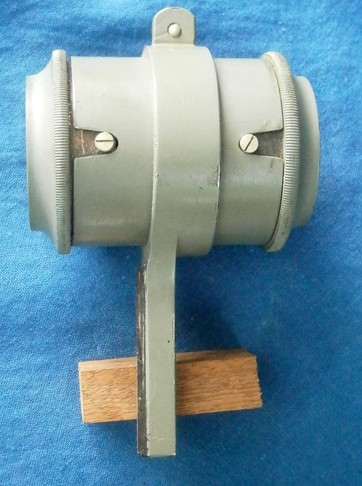
Figure 13: Peep sights in holder.
There seems little point to having the aperture with the round hole (Figure 14) since a perfectly adequate view of the cross vial is had without it.

Figure 14: Peep sight apertures.
Lighting system
Tamaya was probably the first to use a perspex light guide to carry light from a bulb to the scales of a sextant (Figure 15). The substantial black plastic handle contains a 1.5 volt “C”cell that provides current via a simple push button switch to the bulb (Figure 16). Earth return is via the body of the sextant and a special potentiometer in the bottom of the handle.

Figure 15: Scale lighting.
Figure 16 shows the interior of the battery handle and some of the wiring. Note that the switch controls lighting to both the scales and the level unit. though both are not illuminated at once. Instead, the special potentiometer controls the intensity of the light to each in turn.

Figure 16: Battery handle.
At the front or left-hand end of the limb is a hole to accept the holder for the bulb that lights the level unit. The blank shade, the knob for which is visible at bottom left of Figure 16 is rotated upwards to prevent stray light from shining upwards and light from the lamp can then reach the white reflector and be diverted into the unit. In fact, relatively little light finds its way inside and in full darkness it is rather hard to make out the cross level bubble.

Figure 17: Level lighting.
The exterior of the potentiometer is shown in Figure 18, together with the socket for external power and Figure 19 shows the internal construction of the device.
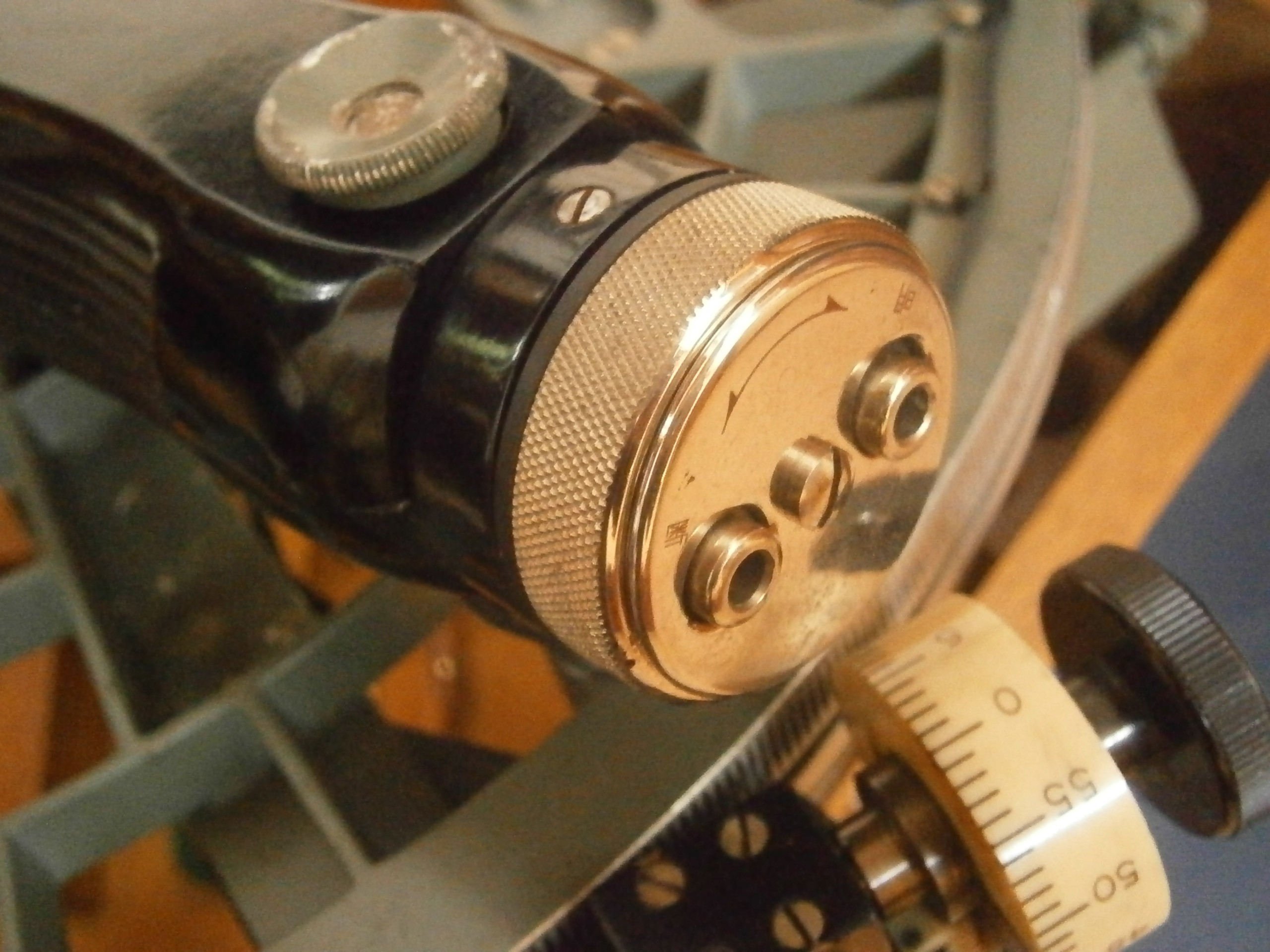
Figure 18: Potentiometer knob and power socket.
There are two separate resistance windings with a wiper inside the knob being common to both and the knob carries current from the battery via the central screw and metal cap. Each bulb may be switched on and its intensity controlled in turn, but not together, and the battery handle switch must be depressed for either to light.
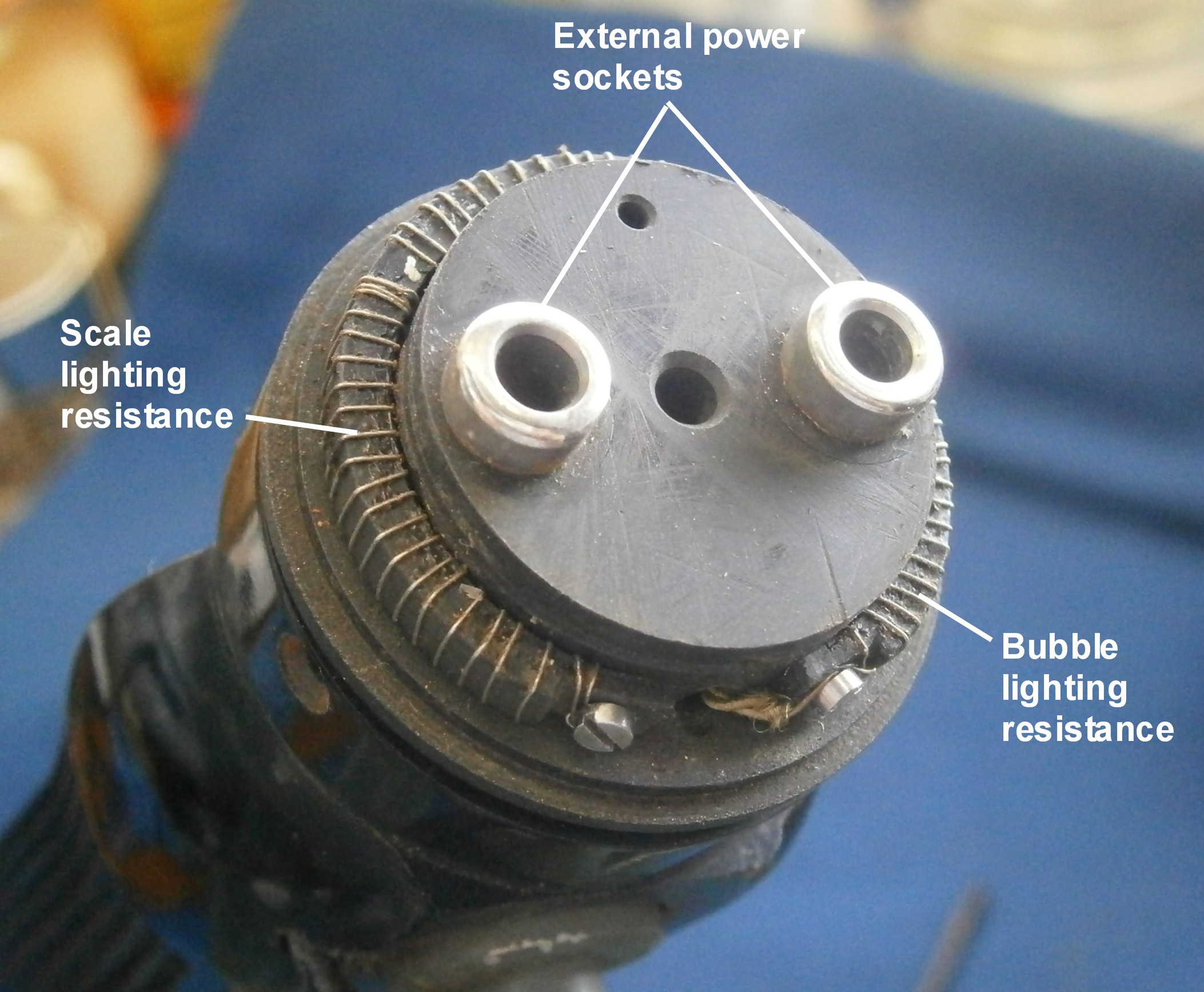
Figure 19: Interior of potentiometer.
According to Freidrich Jerchow’s history of C Plath, From Sextant to Satellite Navigation, the sextant enjoyed some popularity in its fully developed form in the 1930s at a time when airships were seen as the long-distance aircraft of the future. It was probably quite suited for use in airships, which are notably stable and little subject to the effects of air turbulence, but as airships fell into disuse, so the sextant was overtaken by the development of other bubble sextants, all of which had circular levels and all of which directed an image of the bubble, apparently at infinity, into the light path via beam splitters. The particular sextant which I have described, however, has a placard indicating that it was made, or at least, sold, in the ninth month of the nineteenth year of the Showa dynasty (Figure 20) or September 1944, by Tamaya. The stamps each side of the serial number are naval marks. Compared to copies of the A8-A bubble sextant, which were also made in Japan, this would have been an obsolescent instrument and much more difficult to use in a fixed wing aircraft.

Figure 20: Maker’s placard.
For completeness, I show the outside of the case in Figure 21. The furniture is brass with a heavy canvas handle in good condition. The interesting slanting comb corner joints seem to combine the advantages of dovetails with the large glued area of ordinary comb corner joints. Both top and bottom are attached with brass screws and the catch is supplemented by hook latches. I am unable to identify the wood.
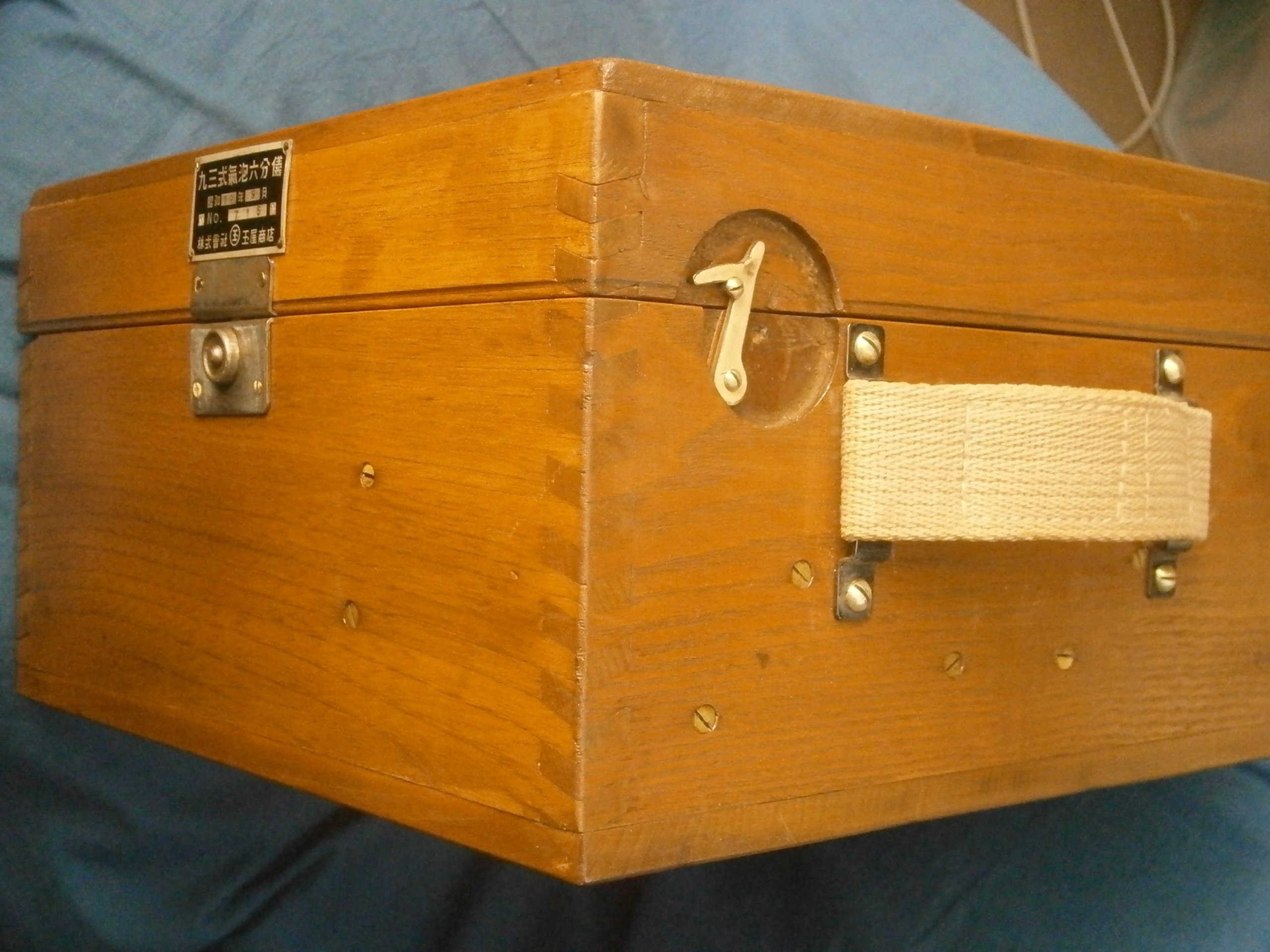
Figure 21: Exterior of case.
I hope you have enjoyed reading about this rare and unusual sextant. You may also enjoy reading my books The Nautical Sextant and The Mariner’s Chronometer.

You must be logged in to post a comment.