You will find an account of the restoration of this sad instrument in the post for 20 October 2016 in the category “Interesting Overhaul Problems.”
A Battered 1940’s Observator Sextant
20 10 2016Comments : Leave a Comment »
Categories : Observator Sextants
Restoring an Observator classic sextant
26 02 2015This post is preceded by one on “The Observator Mark 4 Sextant”.
I was recently asked if I would restore a sextant which had been given to Laura Dekker prior to her setting out from the Netherlands in August, 2010 to circumnavigate the world in a yacht. She had finally come to rest where she had been born, on her parents’ yacht, in the New Zealand city of Whangarei, some 200 km south east of my home in Pukenui. It was my pleasure to undertake the task and later to return the instrument to this remarkable young person. She describes her battles with the Dutch authorities, who refused to allow her to set out at the age of 14 years, and her subsequent voyaging in her book: One Girl, One Dream (Harper Collins, 2014).
I had previously described the interesting Observator Mark IV sextant (April 2014). Laura’s instrument was plainly of an earlier era, probably from the 1950’s. Figure 1 shows the sextant as received. It bears no particular inscription, so I have chosen to call it the “Observator Classic”. The frame is of bronze and the whole sextant is exceptionally heavy at 2.32 kg (5 lbs 2 oz), compared to a Hughes and Son three ring micrometer sextant at about 1.5 kg and a W Ludolph sextant of similar robust build at 2.05 kg. It has a lighting system and as Figure 1 shows, corrosion had caused the lighting fixture to part company with its stem (All figures may be enlarged by clicking on them. Return to the text by using the back arrow.).

Figure 1: Sextant as received.
Figure 2 shows the condition of the rack and the entry to the battery compartment, complete with long-dead batteries. One can also see the exceptionally heavy ribbing of the frame, suggesting that it was perhaps a sand casting. Patient wire brushing restored the battery compartment to a conducting state while, once the stem of the lighting fixture had been persuaded away from the index arm fitting, it was the work of a few minutes to silver solder the stem back into place.
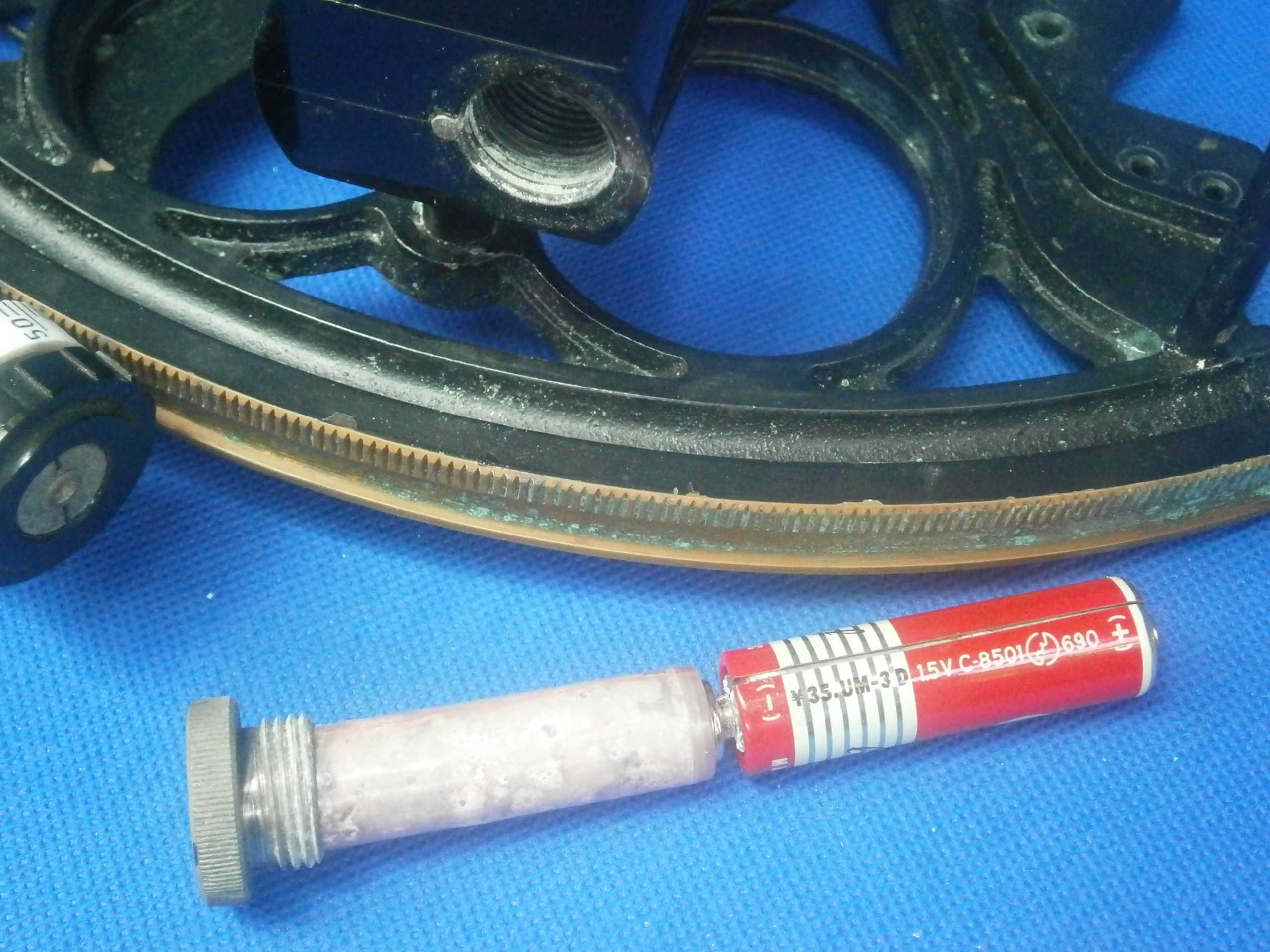
Figure 2: Rack and battery compartment.
Figure 3 shows the structure of the micrometer worm and its shaft, perhaps somewhat over-engineered, but robust and adequate to purpose. The shaft has a taper on to which the worm is forced by a nut to ensure concentricity of the worm. At the other end of the shaft , a combined thimble and drum screws on to the shaft. It is located by a parallel register ahead of the threaded portion and secured in place by a locknut. The shaft rotates in two bearings in a bronze swing arm and axial preload is provided by a spring which is held in place by a cap that screws into the swing arm.

Figure 3: Micrometer exploded.
Figure 4 shows more detail of the micrometer mechanism. The cone ends of two screws, one each side of the swing arm engage with conical holes at each end of the arm and these screws are adjusted so that there is no end play but the arm can rock freely between the two screws, which are then locked. A leaf spring (not seen) between the swing arm and the lower end of the index arm holds the worm in engagement with the rack and the worm can be disengaged by squeezing the two together. Extensions of the trunions that house the cone-ended screws act as keepers to prevent the lower end of the index arm from lifting off the frame and keep the worm aligned with the rack.

Figure 4: Detail of micrometer mechanism.
The telescope rising piece design lies somewhere between the more-or-less elaborate nineteenth and early twentieth century arrangements for adjusting the height of the telescope above the frame (see, e.g. https://sextantbook.com/?s=fine+C+Plath), and the very simple later vee and flat used by most makers after about 1950. The telescope rising piece is square and fits closely into a socket screwed to the frame. A thumb screw locks it into position (Figure 5).
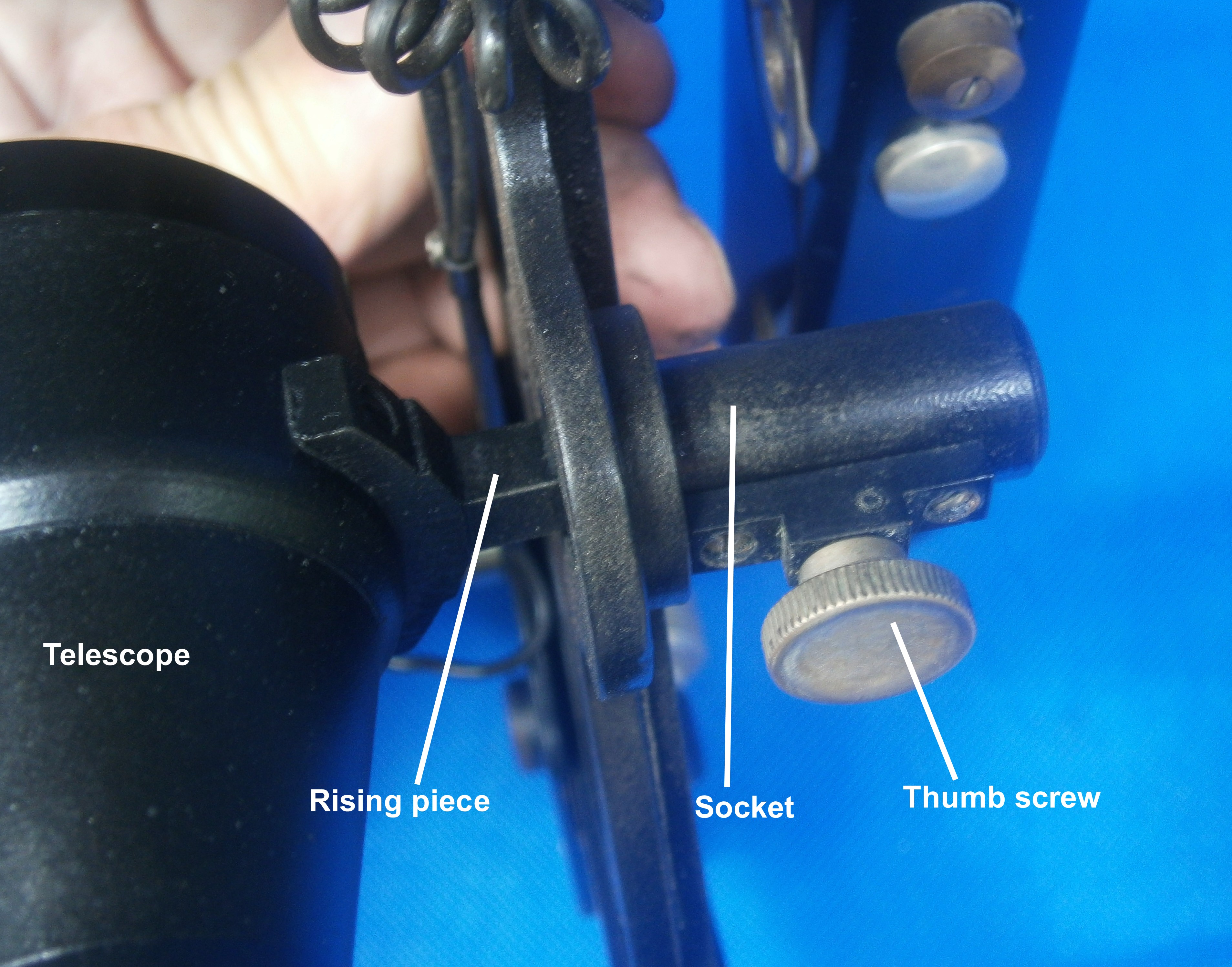
Figure 5: Telescope mounting.
After cleaning up, making and replacing the mirrors, it remained only to repaint the instrument to give the pleasing result shown in Figure 6 and to clean up and re-varnish the case (Figure 7).

Figure 6: Finished instrument.

Figure 7: Restoration complete.
Comments : 2 Comments »
Tags: sextant
Categories : Observator Sextants
The Observator Mark 4 sextant
24 04 2014Rather Like C Plath’s Navistar Professional sextant (see Eighty Years of Carl Plath Sextants, 13 November 2012), the Observator Mark 4 sextant arrived on the scene from Rotterdam just in time to be made obsolescent by the advent of global positioning systems. Like the Navistar Professional, it too had features that were probably a source of annoyance to the practical navigator. Figure 1 shows a general view of the front or left-hand side of the instrument. (All figures may be enlarged by clicking on them. Return to the text by using the back arrow.) There are several striking features: the frame has none of the traditional bracing; there are no shades to be seen; the index arm is on the back of the frame;and the very squat telescope is almost as one with the frame, as well as having a variety of knobs.
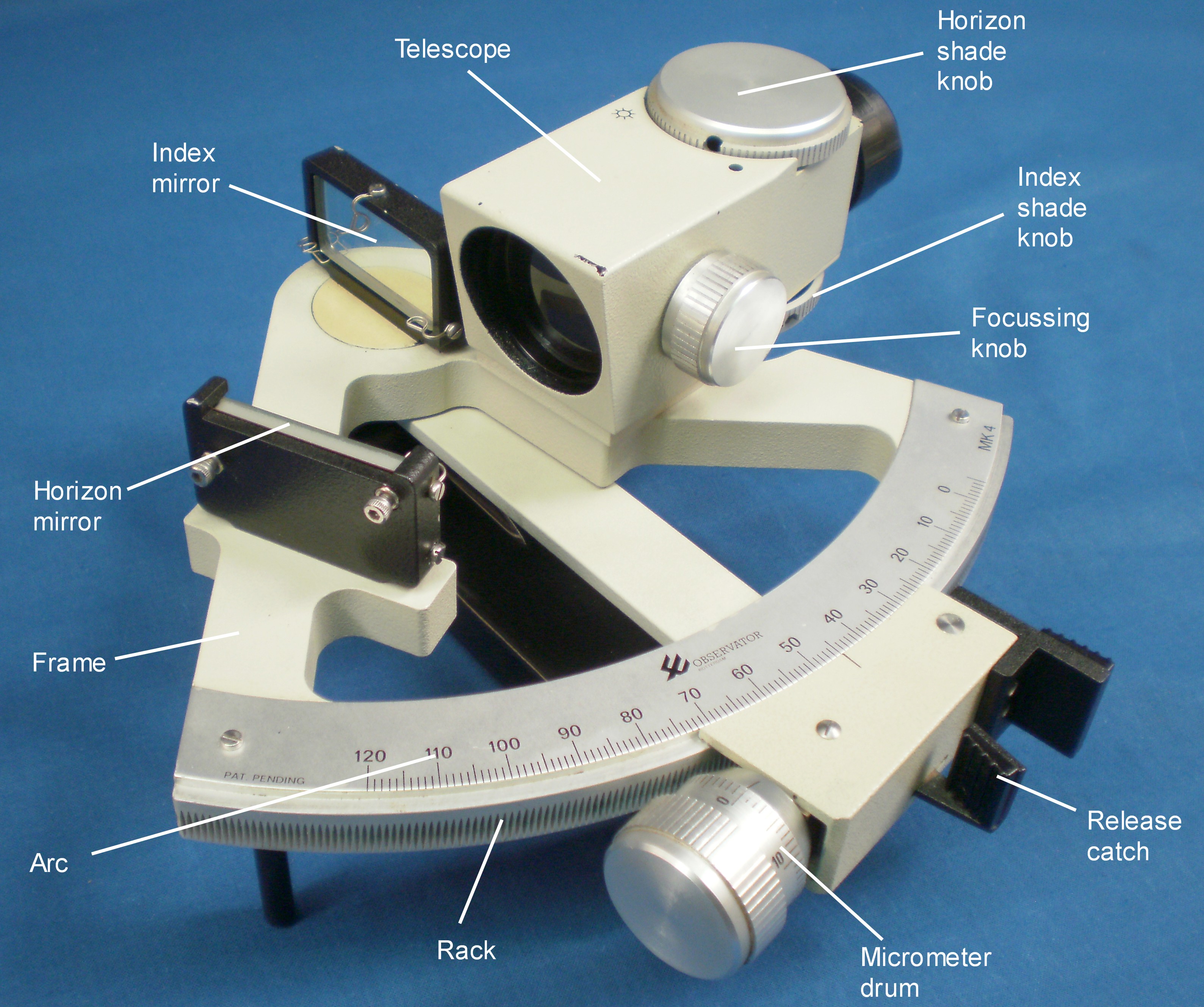
Figure 1: General view of front of sextant.
On turning over the instrument to see a rear view (Figure 2) it becomes immediately apparent that it is a little awkward to do so with one hand because of the shape of the frame. The handle is then seen to be a very stout alloy casting attached only at the top by three Allen screws, and the micrometer mechanism is seen to be totally enclosed within a U-shaped casting attached by three screws to the lower end of the index arm. A further knob is revealed on the back of the telescope.

Figure 2: General view of the rear.
Figure 3 shows the structure of the frame, a heavy, monolithic aluminium alloy casting 15 mm thick, with the index arm bearing and the rack machined directly into it and with the engraved arc screwed and glued to the limb. The whole instrument weighs 1.9 kg (4 lbs 3 oz), rivaling the heaviest of traditional bronze sextants.

Figure 3: The naked frame.
The word “bearing” is often taken to mean the rotating part plus its enclosure, but strictly, the central rotating part is the journal and the enclosure in which it rotates is the bearing; and I have kept to this traditional nomenclature in Figure 4. The large diameter journal carries the index mirror bracket which is attached to it by two screws from below. The large diameter bronze journal rotates in the bearing which, as in the Soviet SNO-T sextant and the Freiberger sextants, is machined directly into the frame and which seems to be anodised for hardness. The upper end of the index arm and a retaining washer are located by a central spigot on the journal and attached by means of two countersunk screws from the rear. The index arm is a piece of 25 x 5 mm rectangular aluminium alloy stock.

Figure 4: The index arm bearing parts.
The index mirror measures 25 x 50 mm and has the usual springs to retain it in its bracket and an Allen screw on the rear to adjust for perpendicularity. The horizon mirror (Figure 5) is of the same size and is fully silvered. That is to say, there is no plain glass portion through which the horizon is viewed, but rather it is viewed directly. With a half-silvered mirror, about 10 percent of the light from the index mirror, assuming it is of a size to do so, is reflected off the front and back surfaces of the unsilvered portion of the glass and the effect when the telescope is a Galilean type is to widen the area of view where the direct and reflected images coincide. This makes it rather easier to judge when the observed body and the horizon coincide. The top of the bracket, otherwise identical to the index mirror bracket, has been machined away so that the view over the edge of the mirror is unimpeded. There are the usual springs and screws to adjust for side and index error. Both brackets are very robust and strongly mounted, and it would take considerable force to displace them.
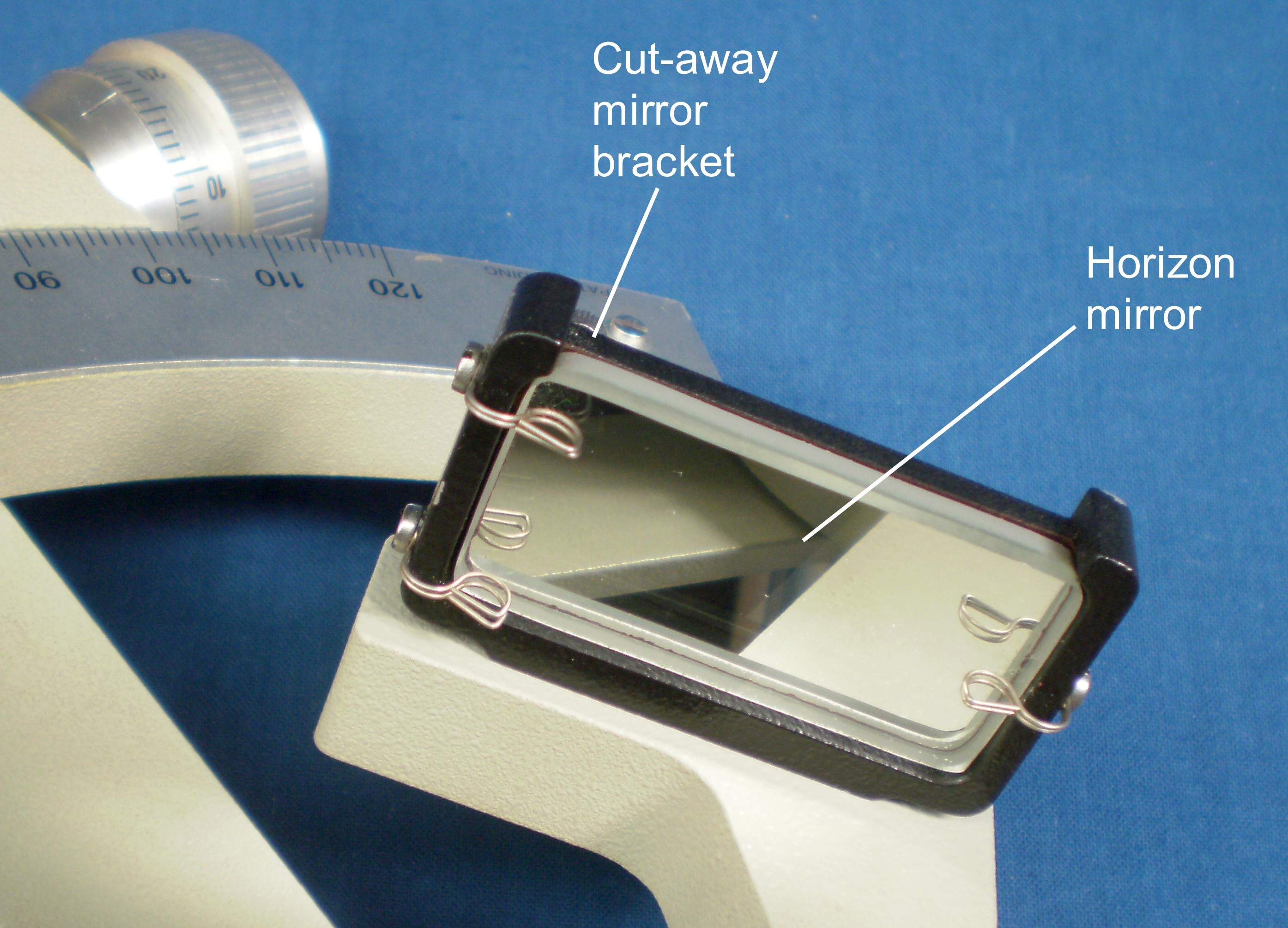
Figure 5: Horizon mirror and bracket.
The telescope, which contains the shades within it, is perhaps the most unusual feature of the Observator Mark IV sextant. Figure 6 is a cross section through the telescope, modified from Figure 3 of the patent document for the sextant, filed in December 1982. The telescope is a Galilean type in which, in effect, light from the left half of the field stays in the left half of the telescope while light from the right half of the field stays on the right. This is perhaps easier to understand by covering half of the objective lens of such a telescope, when it will be seen that the corresponding half of the field will go dark, but if this is repeated with a Keplerian or inverting telescope, the field will simply go dimmer, while the full field of view is retained.
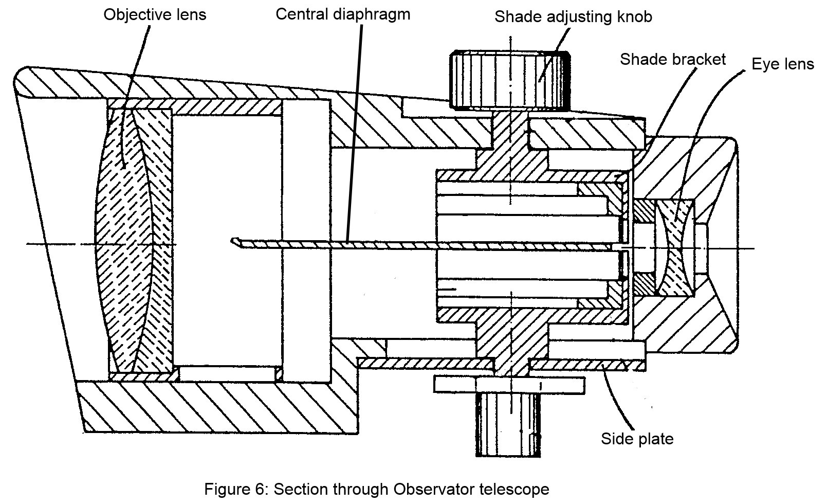
Observator took advantage of this characteristic of the Galilean telescope by inserting a filter or shade in each half of the light path inside the telescope, so that the intensity of light from the observed body and from the horizon could be independently controlled at the telescope by means of curved filters of continuously varying density, from light orange to deep red. A central flat diaphragm lies along the axis of the telescope, as seen in Figure 7, which also shows the objective lens in its cell. I am not sure about the intended effect of this diaphragm, but one effect is that a distracting vertical line lies in the field of view and that it is difficult to get a view of the horizon and the body at the same time, as there is very little overlap of images

Figure 7: Central axial diaphragm of telescope.
Figure 8 shows the form of one of the shades, in which a piece of coloured photographic film is held in a curved holder which can be rotated by means of a large external knob to bring different parts of the film into the light path. There is also a semi-circular notch in the bracket that allows light to pass unimpeded.

Figure 8: Details of shade mounting.
Focusing is carried out by moving the objective lens axially by means of an external knob and a crank that engages with a slot in the objective lens mounting (Figure 9). Magnification is about four times and colour correction is not complete, with coloured fringes being visible on a bright horizon, though as soon as the filters are deployed this is unlikely to be a problem. Operation of the focus and shades controls is easy, but the field of view is disappointingly small, especially for wearers of spectacles.

Figure 9: Focusing mechanism of telescope.
The main advantages claimed for the telescope are that the shades are kept free from dirt and damage, inside the telescope. These advantages have been bought at the cost of complication, balanced by the negligible cost of the photographic film, but the film is practically in the focal plane of the objective lens, and in my example the index filter had been damaged by heat. This was easily remedied by reversing the film edge for edge in the bracket.
Figure 10 shows the micrometer mechanism detached from the index arm. End play of the worm in its bearing is taken up by a spring pressing on a ball bearing. The bearing of the worm is screwed to a bronze swing arm that swings about a pivot under the influence of the release catch, the end of which is just visible in the Figure 10 above the worm. The catch passes through a slot in the base of the micrometer mechanism casting and acts as a crank to rotate the swing arm and its attached worm out of engagement with the rack. Many sextants when dropped suffer damage to the release catch and shades, but the one is very robust and the other out of danger inside the telescope. Although in a classical sextant there may also be a worry that the frame has been bent, this is unlikely in an alloy-framed instrument and it is difficult to imagine that it might happen to the frame of this instrument.

Figure 10: Micrometer mechanism removed from index arm.
The exploded view of the mechanism in Figure 11 shows how a leaf spring beneath the swing arm presses the worm into engagement with rack. The 15 mm diameter drum is divided into minutes and, unlike that of the Plath Navistar Professional, is easy to read, though there is no provision made to illuminate it.
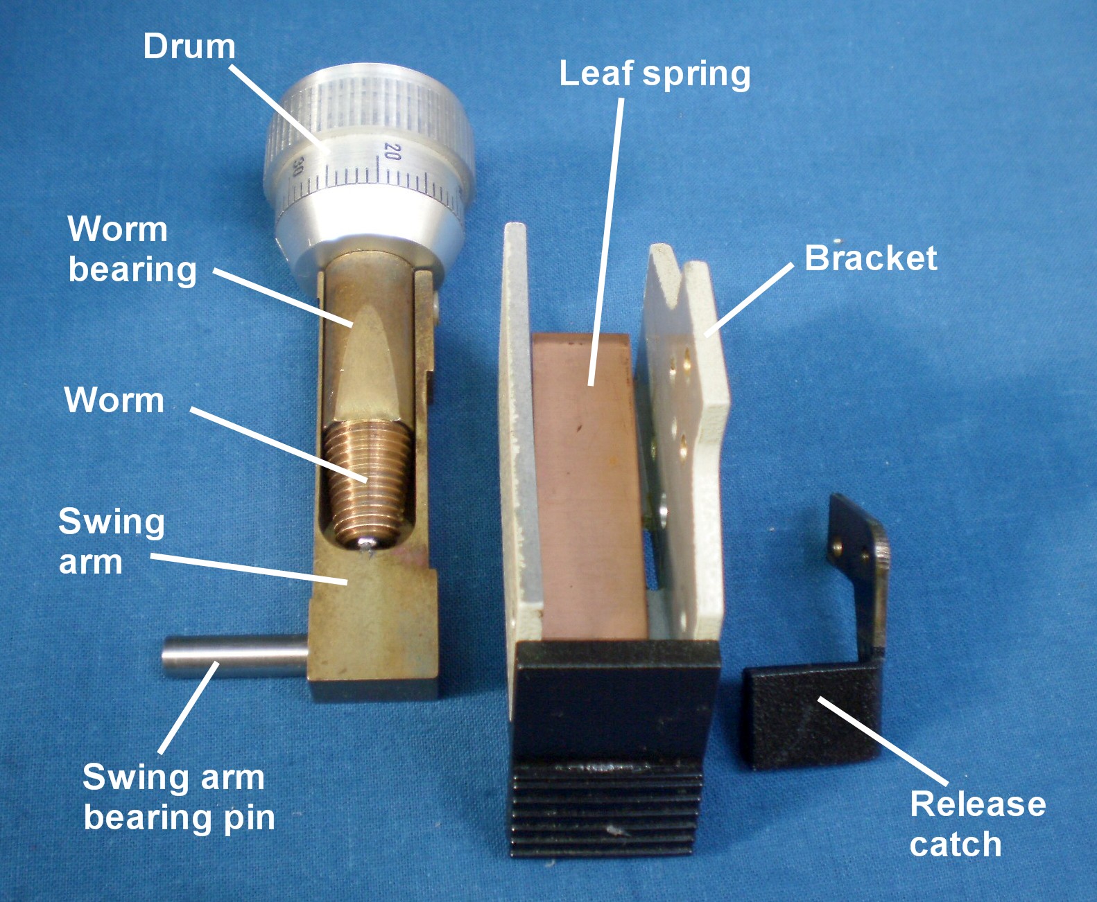
Figure 11: Micrometer mechanism details
The case is made with solid mahogany walls with corner rebate joints and plywood top and bottom. The hinges and other hardware are of plated steel. It is provided with an oil bottle and an Allen key for adjusting the mirrors. The index arm must be set at 45 degrees in order for the sextant to fit face down in the case, a minor annoyance only. If it is necessary to set it down on a flat surface, it tends to rest on the telescope and micrometer, both of which are rugged enough to stand it, rather than on a mirror or shade as in conventional instruments.
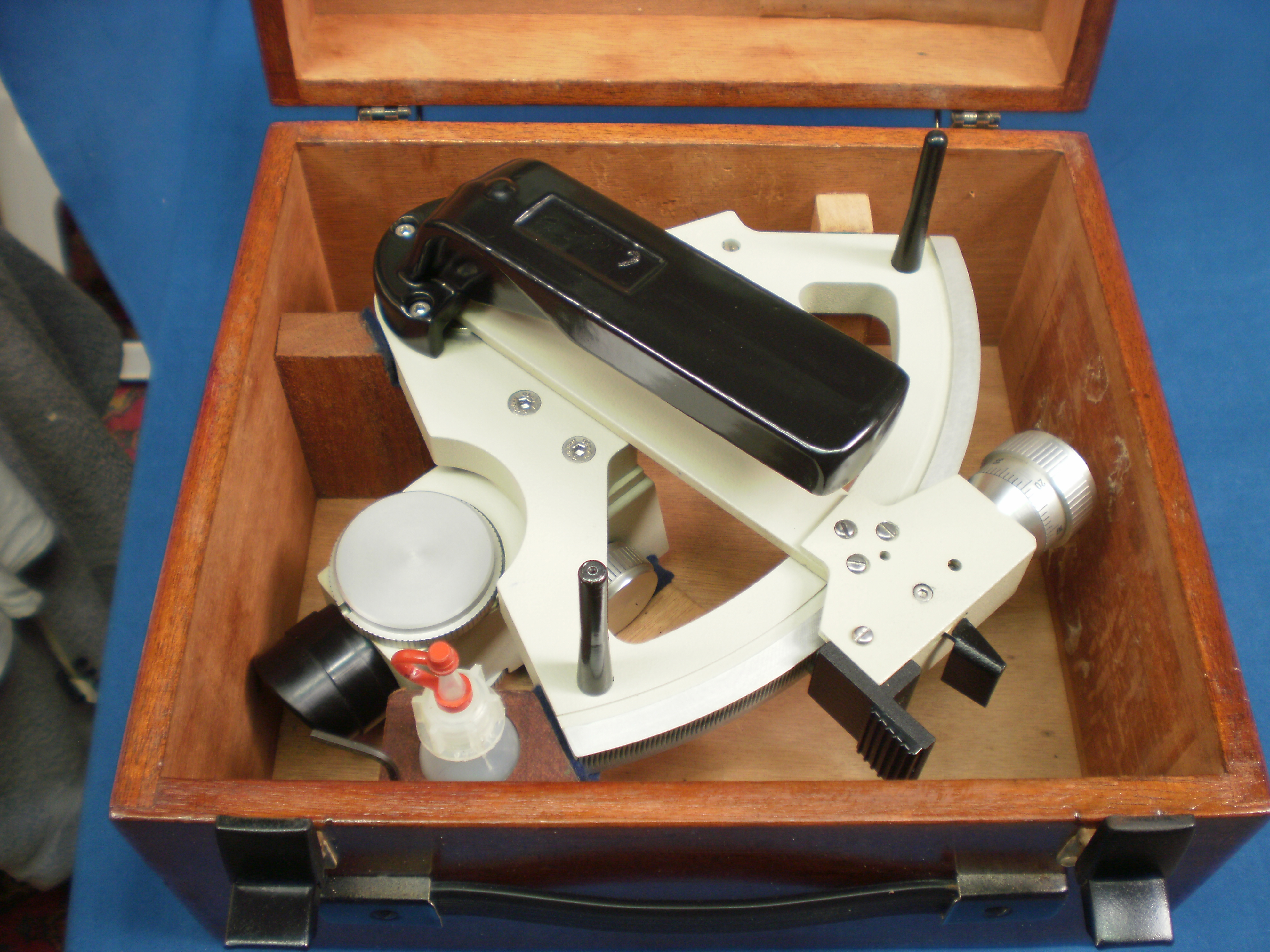
Figure 12: Sextant stowed in its case.
This is a rugged instrument whose weak points other than the consequences of a fully silvered horizon mirror are the poor colour correction of the telescope and its rather small field of view, and a poorly shaped handle that gives a sense of imbalance when taking shots.
If you have enjoyed reading this account, you will probably enjoy reading my book on the structure of sextants, “The Nautical Sextant,” and if you are interested in the instruments of navigation, my other book, “The Mariner’s Chronometer,” may also be of interest to you
Comments : 2 Comments »
Categories : Observator Sextants

You must be logged in to post a comment.