The preceding posts in this category cover : “C Plath battery handle structure; “C Plath sextant lives again”; “C Plath Micrometer Sextant”; “A Damaged Rising Piece”, “SNO-T Mirror Bracket Repair”, “A Worm Turns”, “The case of the broken screw”, and “Worm with wrong thread angle?”
As I have a limited budget to spend on my hobbies, most of the sextants that I buy are damaged to some extent or missing parts or corroded or all three, but where would the fun be in buying pristine instruments? A little while ago, an ebony quadrant which I guestimate to be from the first half of the nineteenth century came into my hands for much less than an instrument in good condition would cost. My experience may help readers with their own restoration projects. I do not claim to be an expert wood worker or that there are not other ways to proceed, only that my methods work after a fashion.
First a word about the term quadrant. Most mariners of the time would observe a heavenly body to obtain latitude, either by observing the maximum altitude of the sun to obtain local noon or, in the northern hemisphere only, by observing the altitude of Polaris, the Pole Star, again obtaining latitude with only small corrections and the minimum of calculation. As the altitude of heavenly bodies never exceeds 90 degrees, an quadrant would do for the observations. It was also often called an octant, Hadley’s quadrant or simply “a Hadley”. As rotation of the index mirror through a given angle rotates the reflected ray through twice this angle, each degree on the scale of an octant (or, for that matter, a sextant) is only half a degree of a full circle, so that 90 degrees of measured angle or a quarter of a circle can be accommodated on a scale of only an eighth of a circle in length, hence “octant”. More sophisticate navigators might attempt to obtain their longitude by the method of lunar distance, for which a sextant, able to measure altitudes up to 120 degrees, was required. Figure 1 shows the face of the instrument as received. (Clicking on the pictures enlarges them. Return to the text by using the back arrow). The frame is of heart ebony, a black or dark brown African wood which is very stable and hard. It is also unfortunately prone to splitting and flaking. The figure shows that the octant is very dirty, it lacks the vernier scale and name plate, and the ivory main scale or arc has detached itself from the limb.

Figure 1: Face of octant as found.
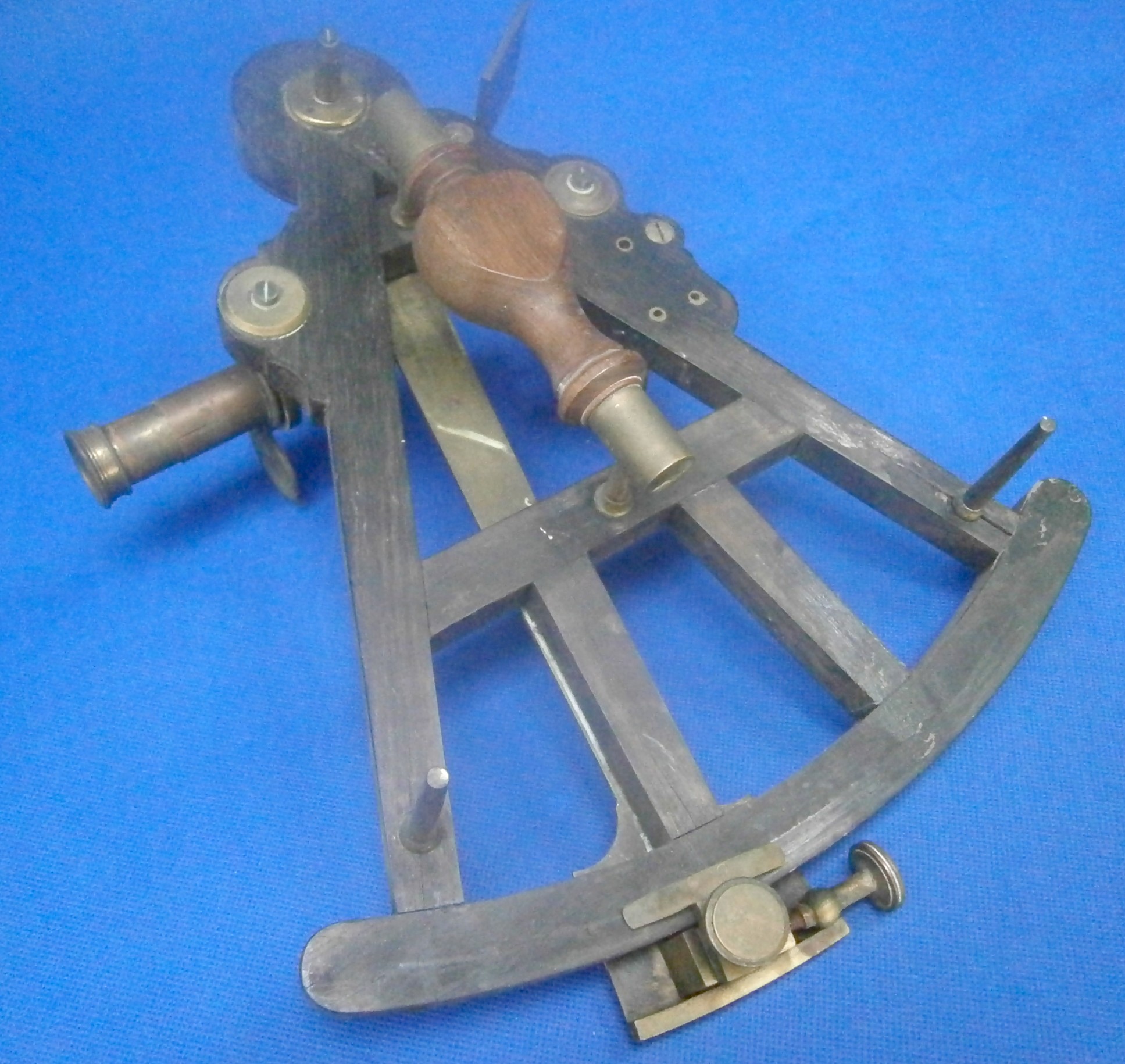
The rear view, shown in Figure 2, shows some of these cracks at each end of the limb where the legs of the sextant have been screwed into the back of the frame. It is not possible to see that the tenons are loose in their mortises and that there was a large flake loose in the vicinity of the rear of the index arm bearing. Happily, all the brass parts, including a small Galilean telescope and a sighting tube, were intact. It is interesting to see in the rear view that there are three brass inserts that seem to have no function in this instrument. Some earlier instruments had elaborate methods for correcting side and index error and these brass inserts would have been used to attach these devices. Plainly, there were specialist frame makers, scale dividers, telescope makers, shade and mirror bracket makers and so on. The person who placed his or her name on the instrument, and there was at least one female instrument maker, was very often merely the person who assembled bought-in parts into a whole, rather like modern-day car makers. Perhaps an instrument maker was told that he could have any frame he liked as long as it was the one that the frame maker had in stock.

Figure 2 Rear face of octant as found.
Figure 3 shows the mahogany case which from its condition had plainly not been stored in a dry place. As all the joints were loose and the box lock interior was a mass of rust, perhaps it had even been submerged at some point. The base had so many splits in it, with loss of wood around the steel nails that it was beyond repair. One hook latch was still present and it was possible to pull apart the joints easily after removing the top and bottom. The steel screws securing the hinges had not only corroded beyond saving, but the swelling of the rust had also partly destroyed the surrounding wood. Only one hinge remained.

Figure 3: Case as found.
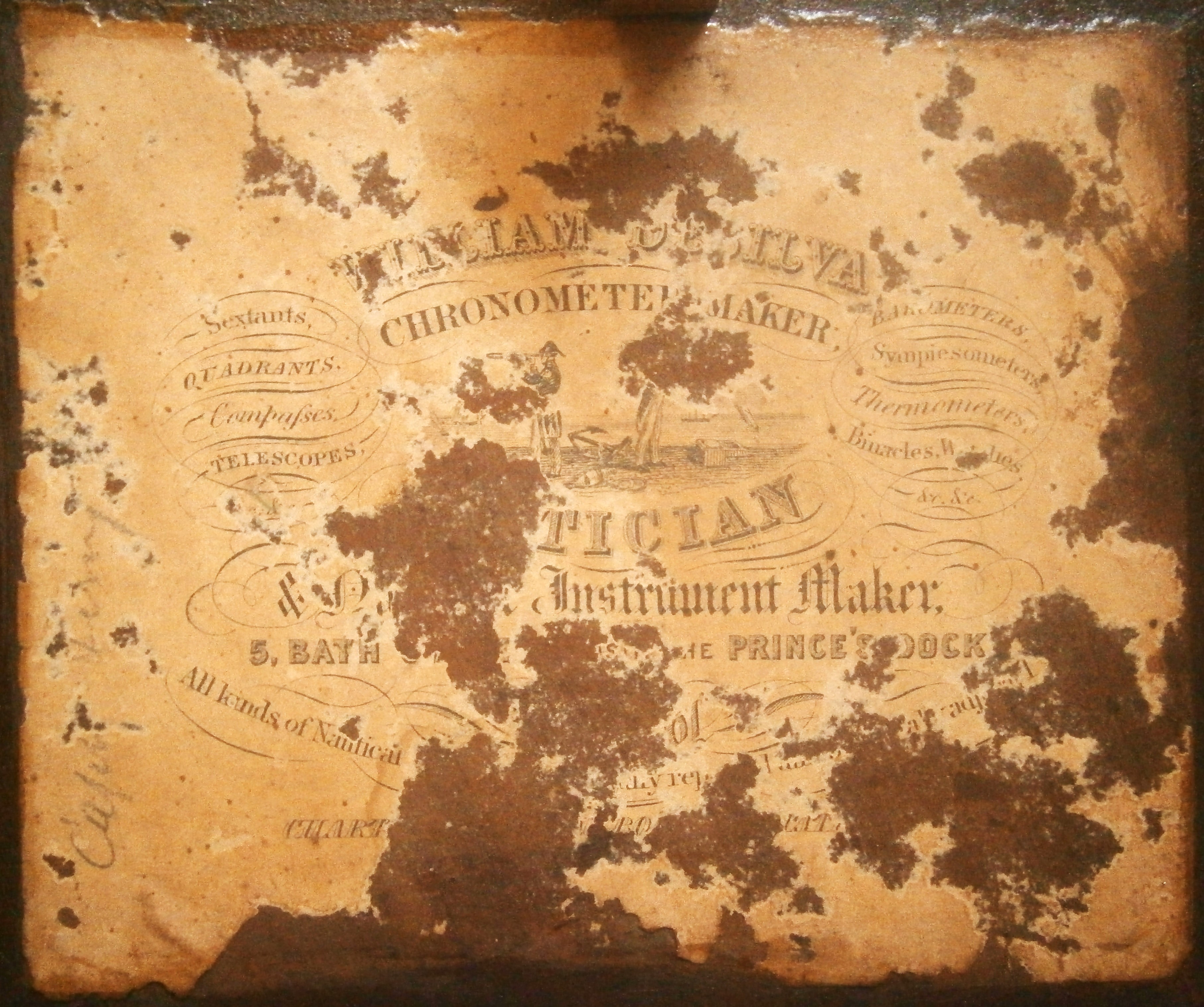
In the lid were the remains of a label of William de Silva shown in Figure4. In the census of 1881 there was a William de Silva, “Optician” aged 59 years, living in Liverpool. He was possibly the son of Manuel de Silva noted in the census of 1841 as having been “born in foreign parts.” William had a son, also William, whose age in the 1881 census was given as 36, occupation Master Mariner. Prince’s Dock was begun in 1810 and completed in 1821. Bath Street overlooks the dock. It seems safe to say that the instrument was at some time sold by De Silva and may even have been made by him, in which case it seems reasonable to place it in the first half of the nineteenth century.

Figure 4 : Label of probable maker.
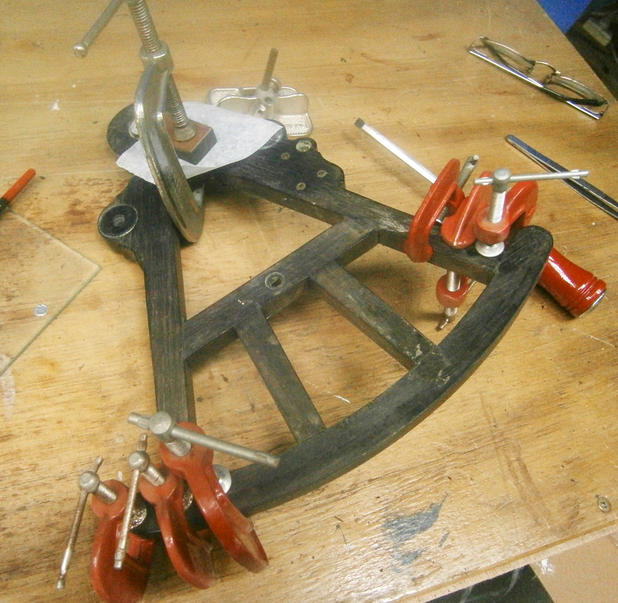
Figure 6 shows some of the frame repairs in progress. All the brass parts have been removed, the mortise-and-tenon joints re-glued and the splits repaired. The latter is done by prising open the split and introducing modern PVA glue into the split, using a fine blade or piece of shim stock to encourage the glue into the deepest recesses. The crack is then forced closed using as many cramps as can be accommodated. At the left of the picture it can be seen that the mortise cut into the right hand end of the limb has split apart and been re-glued. The large flake at the top has been glued back into place and a block of wood used to keep it there while the glue dries. Modern baking paper is very useful to prevent items sticking to things they ought not to. The ivory arc needed careful handling as it had shrunk and detached itself from each end, forming a curve in the process. A previous owner had tried unsuccessfully to replace it using contact adhesive and removing the old glue was a quite difficult job.. I replaced the arc using a modern gap-filling adhesive, but was not entirely successful at preventing splitting at the high end of the arc. However, the shrinkage of the arc meant that it could never again be used in anger so I was not too upset.

Figure 5: Frame being re-glued.
Re-assembling the case was not too difficult. While the walls and top were apart, I used a cabinet scraper to remove all the old and perished varnish. I find that once the knack of sharpening the scraper has been learned, this is a quicker method of getting down to bare wood, as well as needing less exertion than sanding. Some splits and shrinkage cracks meant I had to have recourse to glue and mahogany paste to make good the losses. As noted above, the base was beyond repair, so I made a new one from some 5 mm thick mahogany board, cut slightly over-size. My board was not wide enough to cover the whole of the base, so I added a piece to one corner. To make a rubbed joint to unite two pieces of board with glue, it is essential for maximum strength that the edges should be both straight and square. Figure 6 shows how I planed the edges with a smoothing plane fitted with a home-made fence to ensure the edge was square.

Figure 6: Edge planing without tears.
Figure 7 shows a method of clamping boards of irregular shape while the joint dries. A piece of modern baking paper separates the two parts from a piece of flat and true board. Two clamps hold the large piece immobile and another two clamps hold the smaller piece in contact. It is tapped lightly with a soft mallet until a glue line appears and then the clamps are tightened to hold the boards firmly together.

Figure 7: Clamping an edge joint.
Figure 8 shows the finished result.

Figure 8: Finished joint.
The way the top and bottom of sextant cases are attached varies quite a lot. Unfortunately, steel panel pins were often used on the part of the case most likely to get wet, the bottom, as well as on the top. Slightly higher class cases used brass screws on the top, but even very respected makers sometimes left the unseen bottom to steel pins. Only the best cases had brass screws top and bottom and the really high class ones have the screw slots lined up. The staining from corroded steel pins is difficult to remove and often the pins themselves break as they are being withdrawn so that all one can do is to drive the remnants below the surface and start again with brass pins or screws in different places. Whichever type of hardware is used, it is easier to start by gluing the base or top to the carcass. Figure 9 shows this in progress. A large variety of clamps or heavy weights is indispensable to get a good result.

Figure 9: Base being glued to sides.
Figure 10 shows excess base being planed away using a block plane on the end grain. I am taking a fine “sciving” or oblique cut. Experienced woodworkers will not need to be reminded not to plane right to the corner, to prevent splitting, but I sometimes forget to reverse the direction of the cut before reaching the corner and others might too.

Figure 10: Planing across the grain of the base,.
Figure 11 shows the mess left by the swelling of the rusty hinge screws.

Figure 12: Damage from rusty screws.
I tried filling them with epoxy putty, but the screws refused to go where I wanted them, always following the path of least resistance, so in the end I cut out all the damaged wood and let in pieces of mahogany Figure 13) for the pair of new hinges. I was not able to match the single remaining original hinge, so replaced them with a pair of mdern brass hinges.

Figure 13: Case repair in vicinity of hinges.
Once the repairs to the case were complete, I stained the wood to get an appearance similar to that of old dark mahogany and finished with several coats of modern varnish, sanding lightly between each coat. Figure 14 shows the result for the exterior. I used the remaining hook latch as a pattern in order to cut out and file to shape a new latch from 2.5 mm brass sheet and turned up and filed new eyes to match from 12 mm brass bar. After soaking it in CRC I was able to remove most of the rust from inside the lock and file an old key I had spare to shape. Rather to my surprise, the lock now works effectively. I postponed work on the pockets and keepers inside the case until I had finished the rest of the restoration of the instrument. itself.

Figure 14: Finished exterior of case.
Ivory is no longer possible to obtain except from the keys of scrapped pianos and even those are for the most part ivorine, an early form of cellulose-based plastic. I had a few pieces from the scrapped scale of a distance meter and soon had let in a piece to form a new name scale, though for the time being it remains nameless. The ivorine doesn’t have the creamy texture of real ivory, but at least I am following the practice of many professional restorers of leaving the restored part obvious. The vernier scale was one or two orders more difficult. After working out the angular distance apart of the individual graduations I then had to set up the ivorine at the correct radius on the extended table of a rotary table. To cut the graduations so that they do not look amateurish I used a scribing device that I made many years ago and had not used since (Figure 15).

Figure 15: Scribing vernier.
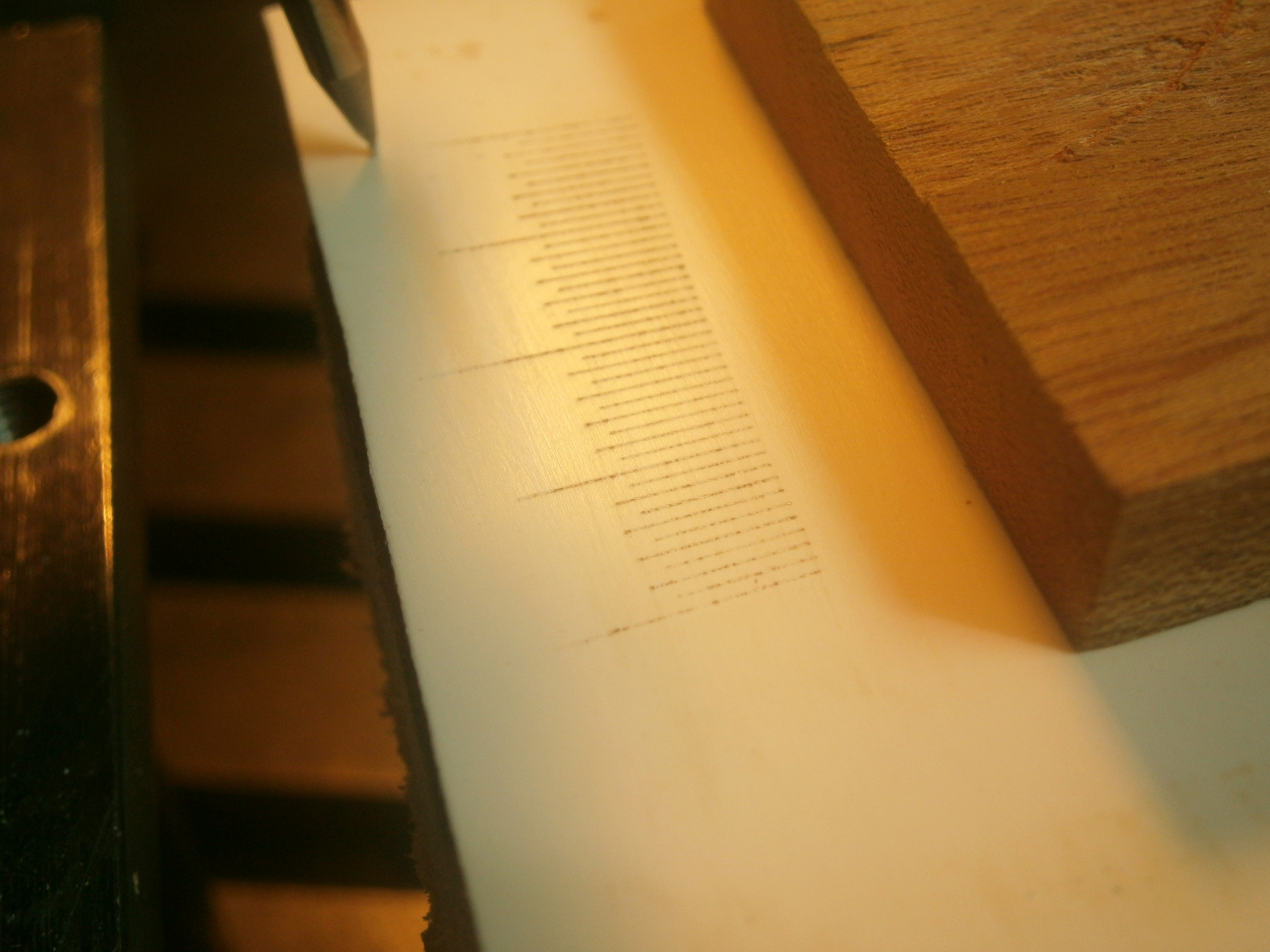
The makeshift, rough version has, as is often usual with me, become the permanent version. A parallelogram mechanism keeps the scriber moving in the same plane under spring pressure and a disc with stops of different heights determines the lengths of the graduations. Figure 16 shows the partly finished scale.

Figure 16: Radial lines scribed.
Once the radial lines were finished, the same scriber was used to mark out the remaining lines, together with guide lines for rough cutting out. The edges were then filed to shape and the underside bevelled to a knife-edge so that the edge of the scale came flush with the main scale (Figure 17). Usually, ivory vernier scales were secured to the index arm with two brass rivets, which caused staining and splitting as the rivets corroded and the ivory shrank. I simply glued the vernier scale into place with epoxy glue.

Figure 17: Completed vernier scale
There was little to do to the remainder of the instrument except to clean the brass parts, repaint them where appropriate and to polish and lacquer the parts like screw heads that were usually left unpainted. While sextants and octants of this period often are shown bright and shiny, on several period instruments that I have handled, I have found traces of paint to guide me on what was usual. There are one or two points of design interest that may not be familiar to some readers. I will be covering the evolution of sighting devices in some detail in another post in the category Evolution of sextant parts, so will give only an outline here.
Figure 18 shows how the index mirror was set perpendicular to the frame. The mirror is held against three points on the front of the right-angled bracket by means of a clip or “keeper”. A central screw when tightened pulls the clip against the front of the mirror and holds the latter firmly against the three points on the front of the bracket. Two lateral fastening screws pass through clearance holes in the base into holes tapped in the index arm. A third screw, labelled “tilting screw” passes through a tapped hole in the base of the bracket so that when the fastening screws are slackened a little, the base can be tilted to the desired right angle be adjusting the tilting screw. This is not a very satisfactory method, as the heavy handed could (and did) bend the base or strip the thread of the screw or hole.

Figure 18 Index mirror adjustment.
Figure 19 shows the pinhole which, at 2 mm in diameter, gives a very wide angle view, compared to that given by the Galilean telescope shown in Figure 20. The diameter of the objective lens of this telescope is a mere 18 mm with a magnification of 6 times. The field of view of a Galilean telescope depends on the diameter of the objective and inversely as the magnification, and in this telescope the field of view is only about 3.5 degrees. Because of this, if Captain James Cook’s practice is anything to go by, sailors used the telescope only when the sea was calm, as it was otherwise difficult to keep the body in view, due to the motion of the ship. The pinhole can be swung aside to allow the telescope to be screwed into the bracket. It can also be swung through 180 degrees so that the hole is offset away from the frame, to give a wider view of the horizon.

Figure 19: Pinhole.

Figure 20: Telescope in place.
A coat of shellac brought back the frame to a pleasing finish and Figure 21 shows the completed instrument in its restored case, with pockets repaired and glued into place, and felts replaced.

Figure 21: Restoration complete.
Because of the shrinkage of the ivory main scale, this instrument is not of course a functional instrument any longer, but it is nevertheless an interesting representation of what the less prosperous sailing ship mariner might have used to find his latitude in the first half of the nineteenth century.
If you enjoyed reading this post, you might also enjoy my book The Nautical Sextant , available through amazon and good booksellers, and my book on the chronometer, The Mariner’s Chronometer, available only through amazon. The reviews on amazon will give you an idea what other purchasers thought of the books.


You must be logged in to post a comment.