I was unsure where to place this post. In the event, I decided it was more restoration than overhaul problem and placed it under “Sextant Restorations” as A Troughton and Simms Survey Sextant.
A Damaged Rising Piece
28 04 2010Comments : Leave a Comment »
Categories : Interesting Overhaul Problems
Troughton and Simms Surveying Sextant
28 04 2010The preceding posts covers “A C19 Sextant Restoration” , “Making a Keystone Sextant Case” , “Restoring a C. Plath Drei Kreis Sextant” , “Heath Curve-bar sextant compared with Plath” and “A Drowned Husun Three Circle Sextant” .
I recently acquired a Troughton and Simms sextant, with all its attachments, but without a case. I find I can sometimes afford such homeless sextants and, after having made ten cases, I can now make them so that they look reasonably in period. It was described in a later catalogue as a “Surveying Sextant, 7 ins., divided on silver and reading by vernier (with magnifier) to 10 secs. ..” In fact, it would also pass as a nautical sextant, as it is provided with the usual seven shades and kit of telescopes and sighting tube. The inverting scope, provided with four wires in the eyepiece, is of 6 power with an effective aperture of 17.5 mm. The star telescopes are 2 power x 17 mm and 3 power x 15.5 mm. The latter may have belonged to another instrument, but both are in the same style.The Troughton brothers were active in London around about 1800. Edward Troughton (b.1765) carried on the business of instrument making after the death of his equally famous older brother, John, in 1788. By 1824, getting on in years, he took into partnership William Simms (b. 1793), describing him to an acquaintance as “the best craftsman he knew.” Troughton died in 1835 and Simms in 1860, but the business carried on as Troughton and Simms until 1916, when it became a Limited Company. It merged with T Cooke and Sons of York in 1922, to become the famous firm of instrument makers, Cooke, Troughton and Simms, with manufacturing being carried out in York, and offices and service centres in London and throughout the then British Empire.
Thus, my sextant is unlikely to be later than 1916, but is otherwise rather difficult to date. There are features like the handle and the index mirror mounting that would place it in the nineteenth century, while the horizon mirror frame is possibly a twentieth century replacement. The cast bronze frame is perhaps a little old-fashioned, while the maker’s name on the limb is in an elegant script, typical of the nineteenth century rather than later stamped typeface. There is little information to be had about serial numbers of this maker. A sextant numbered 1920 is reliably dated to 1836 and if we take forty instruments a year as a reasonable estimate of number made, my sextant would find itself in the last quarter of the nineteenth century. Troughton and Simms made very large numbers of surveying and other instruments during the expansion of the British Empire, and it is likely that sextants formed only a very small part of their output. The next picture shows it as I received it.

The rising piece had a bend in it at the junction with the ring and the telescope ring was heavily corroded with more than a century of verdigris lurking in the crevices:


Plainly, the rising piece had broken the fall of a dropped instrument. In the next photograph, which also shows the handle, it can be seen that the lead screw has punched off the end of the rising piece body. This normally appears to be solid with the body, but is in fact a disc of brass soldered on to the end of the body, as it would not otherwise be possible to form the square hole. The leadscrew is normally held captive in the body, the disc being sandwiched between a flange on the leadscrew and the thumb screw.

In this instance, it was fortunate that the joint gave way, as the rising piece was jammed solidly in the body, and it would not otherwise have been possible to extract the leadscrew. Once it was removed, I could press out the rising piece in the vice:

Once I had the rising piece out of the body and separated from the telescope ring, I could straighten it using a straight edge as a datum, so that it could once again slide smoothly up and down without any shake. Note that there are two recesses machined into the stem of the rising piece for a pair of leaf springs. These I imagine were fitted to help reduce shake, but the mechanism functions perfectly well without them. The thumb screw had still to be parted from the leadscrew. This required only a well-fitting screwdriver and some brute force. I could then clean up the disc and resolder it to the body.
The rest of the restoration simply involved dismantling and cleaning all the parts, followed by fresh coats of black lacquer to the frame and other parts. Then I had to make a case with dovetailed corners and pockets for the various ‘scopes and tools:

I carved the hook latches out sheet brass and had to make the round-headed screws with which they engage, as none of the round headed screws I could find on sale had plain slots. The handle is a drawer pull, which I have provided with a finger plate. I hope the handle does not look too out of place:

The next photos show the maker’s name on the limb…

The structure of the handle is practically unchanged from one from the 1820s. Note the tablet shaped wooden handle, the elegant lower bracket and the way the handle is attached to it with a pin screw. These screws, with two pin holes for a pin wrench were found aplenty in the Troughton Brothers’ famous pillar sextants of the late eigtheenth and early nineteenth century. In these sextants, the frame was formed from two plates about 1.5 mm thick, held apart by about a dozen pillars, to which they were secured by pin screws. Imitating clock-making practice, this gives a relatively rigid and light-weight structure, but was very expensive to make.

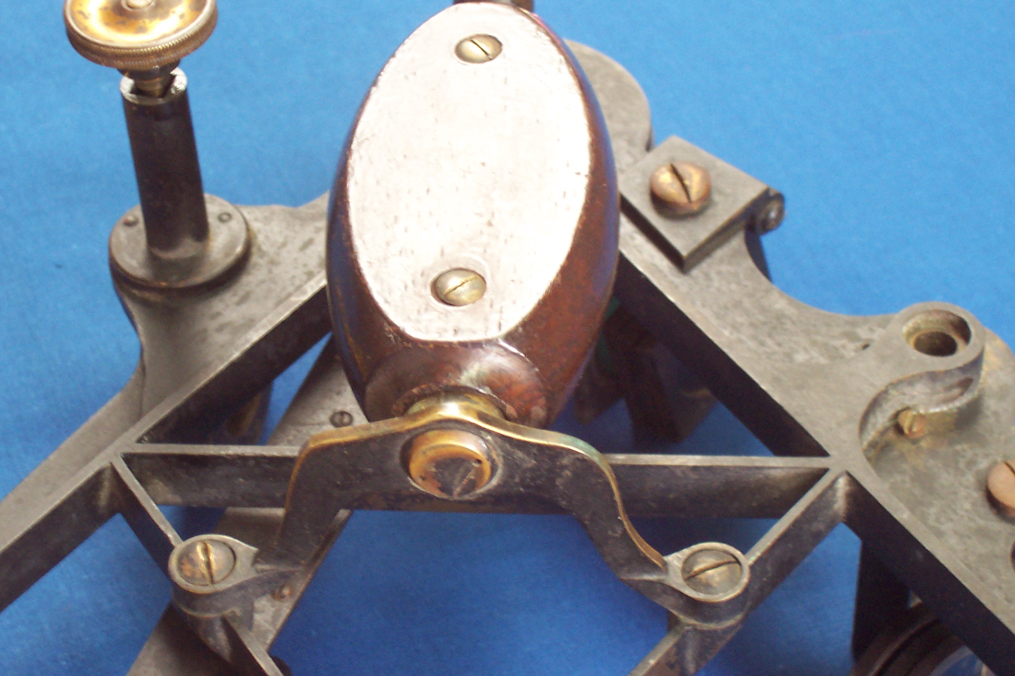
As one might expect from a maker whose principal products were surveying instruments, the tangent screw mechanism follows theodolite practice. A block that can slide in guides on the back of the lower end of the index arm can be clamped to the limb. A tongue projects from the sliding block and is sandwiched between the end of the tangent screw and an opposing spring, both of which are contained in a tubular frame that is secured to the lower end of the index arm. When the clamp is released, the index arm is free to move over the arc. When it is secured to the limb by the clamp, the tangent screw can be used to make fine adjustments and the spring inside the spring box takes care of backlash, which can be an annoyance in a vernier instrument, even though it does not affect the accuracy of the reading. The next photo shows these details in the un-restored instrument:

Edward Troughton originated a dividing engine to rival that of his famous near-contemporary, Jesse Ramsden and described it in the Proceedings of the Royal Society for 1805. With a sextant coming from this background I expected the dividing of the arc and vernier to be of a hight standard and I was not disappointed, as the next photo shows:

(In this and other pictures, you can enlarge them to see more detail by clicking on the picture. Return to the post by clicking on the back arrow.)
Finally, a picture to illustrate the archaic index mirror adjustment. The mirror is held against an angle bracket by a keeper and screw. The bracket is held to the top end of the index arm by two screws and can pivot about two pins adjacent to the screws. A third, adjusting screw rocks the whole bracket.

If you enjoy reading about details of fine instruments, you will enjoy my forthcoming book The Nautical Sextant. You will find some details about it in “About the Book.” Contact me via this site if you would like to be informed when the book goes on sale.
Comments : Leave a Comment »
Categories : Sextant Restorations
SNO-T Mirror Bracket Repair
17 04 2010The SNO-T sextant of the former Soviet Union was possibly one of the best sextants ever produced, but it did have one or two drawbacks, one of which was the method used to lock the mirror adjusting screws. These slender, 2 mm metric screws pass through in turn a bush threaded M6 on the outside and M2 on the inside and then through the back of the mirror cell. Once the mirror has been adjusted, turning the bush through less than a quarter of a turn locks the screw. While using the adjusting screw, the bush can be turned finger tight to firm up the adjusting screw. The bush cannot be withdrawn without first removing the screw, and the screw cannot be withdrawn without first unlocking the bush by turning it a little until it feels slack and can be rotated a little either way.

Unfortunately, the bushes were of thin brass, and the slot used to rotate the bush had sharp corners, so that, in the first place, the bush tended to seize solid in the aluminium bracket, and then the sides of the slot cracked and fell apart when pressure was used to unlock the bush. I have now been asked for help with these bushes three times and the latest was the most difficult to sort out.
One of the previous owners appeared to have drilled out one of the bushes and replaced it with a 6BA cheese headed screw. An off-centre hole had been tapped through the 3 mm thickness of the rear aluminium wall of the bracket. He had also managed to twist off the head of the other screw. The present owner, in attempting to unjam the bush without knowing of its structure, had caused both sides of the slot to disintegrate (this is an observation, not a criticism). Finally, he had attacked what was left with a Dremel tool, leaving an irregular mess of metal in the bottom of the boss on the back of the bracket.
When drilling out a small seized screw, it is next to impossible to start the drill on centre, and if it wanders a little and encounters softer surrounding metal, it takes the path of least resistance. Evidently, then, a twist drill is not the ideal tool to use. However, if you imagine a twist drill with a flat rather than a pointy end, and with one cutting lip extending across the centre line, you have imagined a type of end mill called a slot drill. Fed carefully straight into the work piece, a slot drill will originate a hole and stay on a more-or-less straight line as the hole is made deeper.
Each hole had to be centred beneath the tool before cleaning up the holes. I used a plug of 4.7 mm diameter, the core diameter of the bush, held in the chuck of the machine. This used what was available. I do not claim it is the best method of centring a hole. I replaced the plug with a 3 mm slot drill and fed it straight through the remains of the bushes and back wall of the cell. That took care of the adjusting screw and the bottom of the bush. Maintaining the same centres, I then fed in a 5 mm end mill to remove the rest of the bushes. This left the 6 mm thread in the bosses of the bracket, to be cleaned up with a tap, and 3 mm holes through the back of the bracket, hopefully on the same centres.
I filled up these latter holes by cementing little shouldered bushes in place with industrial adhesive, The bushes were tapped M2 down the middle and were 3mm diameter on the outside, with 6 mm shoulders. As the next picture shows, I had to file away part of the shoulder of the side-error bush to get it to fit.

The average jobbing engineering workshop, while it may have a lathe, is unlikely to have the small tools needed to complete a repair job like this one. An old-fashioned clock maker or instrument maker very likely will, and many amateur model engineers will have small tools, though those in the USA and UK will quite possibly not have metric screwing tackle. For those of you who find someone able and willing to undertake the job at a reasonable cost (or no cost if you’re lucky), a drawing of the parts follows. The unbotching I will have to leave to their ingenuity…
(If you click on the drawing, you will then be able to print it out. Use the back arrow to get back to the post)

From now on, I would like readers to think of my posts as supplements to my comprehensive book on the structure of the nautical sextant. By all means also encourage me to continue by leaving comments and suggestions.
Comments : Leave a Comment »
Categories : Interesting Overhaul Problems
Inside the Skalensextant
4 04 2010In a post about a year ago, I gave an introductory description of this unusual sextant, that uses a glass scale moving past the optics of a micrometer microscope to give a rapid readout in degrees and minutes. Recently, a correspondent in France met one of the same problems as I had, that of being unable to view the degrees scale, and asked me how he could get at the optical system to clean it. Sometimes I am guilty of thinking that what is clear to me is clear to everyone else, so here is a blow by blow account of how to get at the hidden insides of the Skalensextant. The mirrors, shades and telescope are conventional and need no special description.
First, remove the handle by undoing two screws as shown in the photo that follows:

This allows access to the back of the index arm bearing and “index” arm. I’m putting index in inverted commas just this once, to recall that it is not strictly speaking an index arm, since it carries the scale that moves past a fixed index in the viewing microscope. You need to remove the index arm by removing a grub screw…

…and then unscrew what we have to call a bolt (since it is a screw with a shaped head), although the term seems out of place in the context of instruments. If you now operate the release catch, it allows you to wriggle off the index arm from the index arm shaft, given its proper name of journal in the photo. Notice that the grub screw has rather a ragged slot. If you find a grub screw in this state, either replace it or file it smooth and cut a new slot. If it loses its head at the bottom of a hole, it can be very difficult to remove without drilling it out and possibly damaging other parts in the process.

The rear cover can now be removed by undoing six screws as circled in the next photo. You do not need to remove the horizon mirror. Note at this point the little cover held on with two screws, just below and to the right of the upper middle cover screw in the photo.

You can now take a look inside the sextant, but I won’t repeat the description given in the previous post.

Next to come off is the little dovetail slide to which is attached the lighting system. This allow access to the two cheese headed screw that hold the objective assembly to the frame. Remove these two screws…

…and lift out the assembly.

The prism carrier is attached to the objective assembly body by two screws, only one of which has been removed in the next photo because the other one defied all my non-destructive efforts to loosen it. Fortunately, the two right-angle faces are now accessible for cleaning, and traces of rouge that I used to clean up the very heavily soiled lens faces can still be seen on the carrier. Since I could not detach the prism carrier from the rest of the assembly, I was not able to release the prism to get at the hypotenuse face, by my normal method of slowly heating in water from cold until the shellac melts. I give an account in the previous post of why it was necessary to remove what was left of the silvering on the hypotenuse face and how I did it. If after cleaning the other faces, it is possible to get a clear view through the prism, there is no need to touch the third face.

Re-assembly is the reverse of dis-assembly.
Returning now to the little round cover noted above, its removal allows access to the focus adjusting screw. To bring the main scale into focus, first adjust the micrometer eyepiece until the minutes scale is sharply in focus. Then loosen the screw a little until it and the attached objective lens can slide in its slot. Move it back and forth until the degrees scale come into sharp focus. Only one number will be in coincidence with the minutes scale at a time. This reduces ambiguity, but makes it a little difficult to find an out-of-focus degrees number. When you think you have both scales in focus, check that the degrees marker does not move at all over the minutes scale when you move your head a little from side to side (the parallax test), and when you are satisfied, tighten the screw and check again.
In order to buy a copy of my book ,The Nautical Sextant, see the details in “Buy the Book”
Comments : Leave a Comment »
Categories : Freiberger sextants

You must be logged in to post a comment.