A slip of workmanship?

9 01 2023

This post is preceded by “Tamaya Collimation Blunder” and by “Incorrect assembly of SNO-T shades” While this post is about workmanship rather than a blunder, this seems to be the correct category for it.

.A week or two ago, I was contacted by a new friend who in his younger days had sailed in a yacht to many places, travelling over 20,000 miles. In his maturity and now owner of a substantial business shipping people about New Zealand’s Hauraki gulf, he recently bought a 30 foot yacht to resume sailing. On digging out his sextant from storage, he found it had signs of thirty years of neglect and asked if I could help to bring it back to a good condition. I readily agreed.

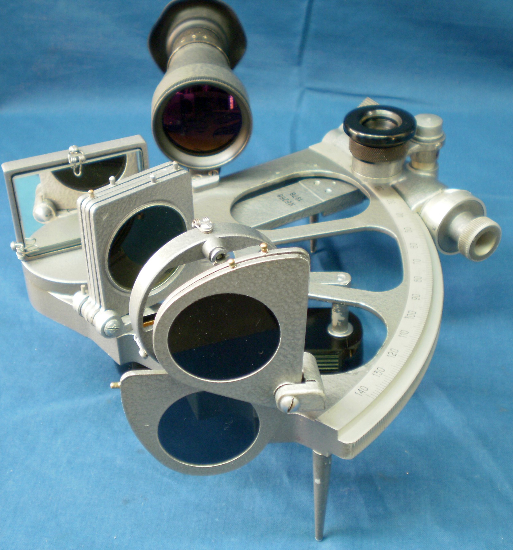
The sextant is a bronze-framed instrument by C Plath, a firm of high repute. It had an inspection certificate dated in 1965 and was contained in a heavy black Bakelite case which appears to be almost indestructible. Such cases were common in Plath sextants made after the Second World War, perhaps because there was a shortage of wood workers, and around 1965, wooden cases with box comb corner joints began to appear. The sextant had minor paint chips and widespread areas of minor corrosion, confined mainly to screw heads and the aluminium frames of the shades. Movement of the index arm and rotation of the micrometer were rather stiff, as might be expected of oil and grease which had had thirty years to acquire the consistency of soap. The telescope focussing in particular needed a lot of care to free it without destroying it. I noted a small area of the objective lens where the cement that joins the two elements of the lens has probably shrunk

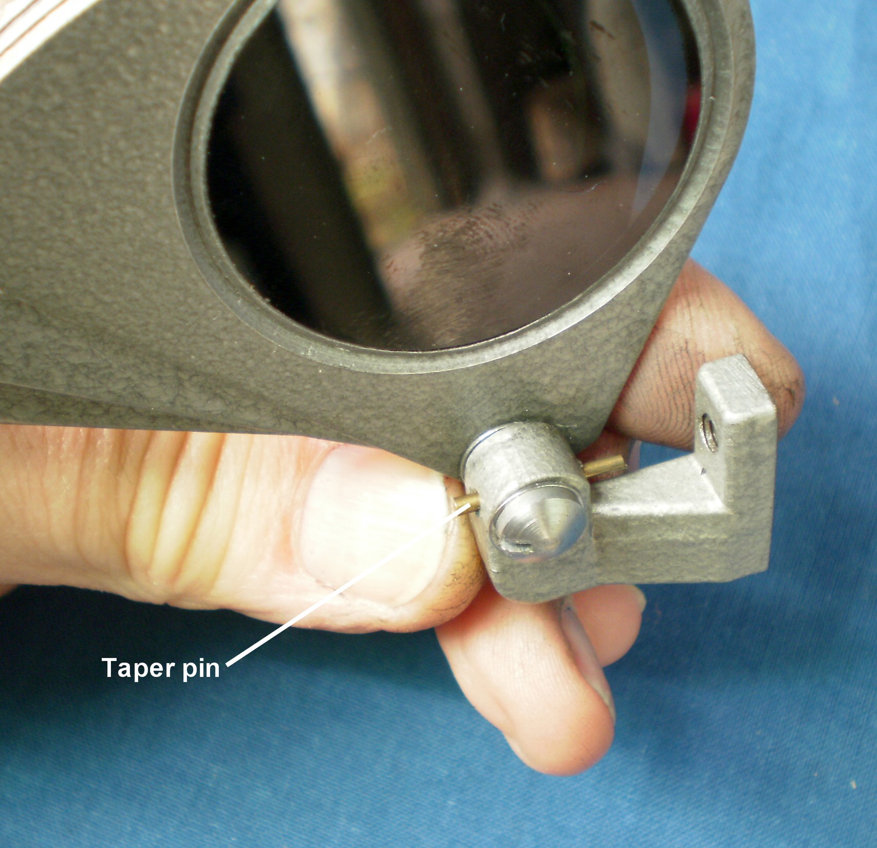
Usually, when I restore an instrument of this vintage I begin by stripping it down to the last screw and washer, beginning by removing the index arm with its attached micrometer assembly. Removing the telescope bracket allows the arm to swing clear of the frame, prior to releasing the journal from its bearing.The bearing is the part that encloses the rotating shaft or journal. Loosely, the two parts are often referred to as the bearing. As soon as the index arm was free of the frame the lower end sprang forward, revealing a distinct bend in the arm at its junction with the upper, circular end. My first instinct was that it had been damaged and I straightened it, when it then appeared to lie behind its proper place. The lower end of the arm has two keepers that slide in a slot on the front of the limb, to keep the micrometer worm in its proper relationship with the rack, while the upper end of the arm is guided by its bearing(Figure 1).

Figure 1: Showing mis-alignment of index arm.

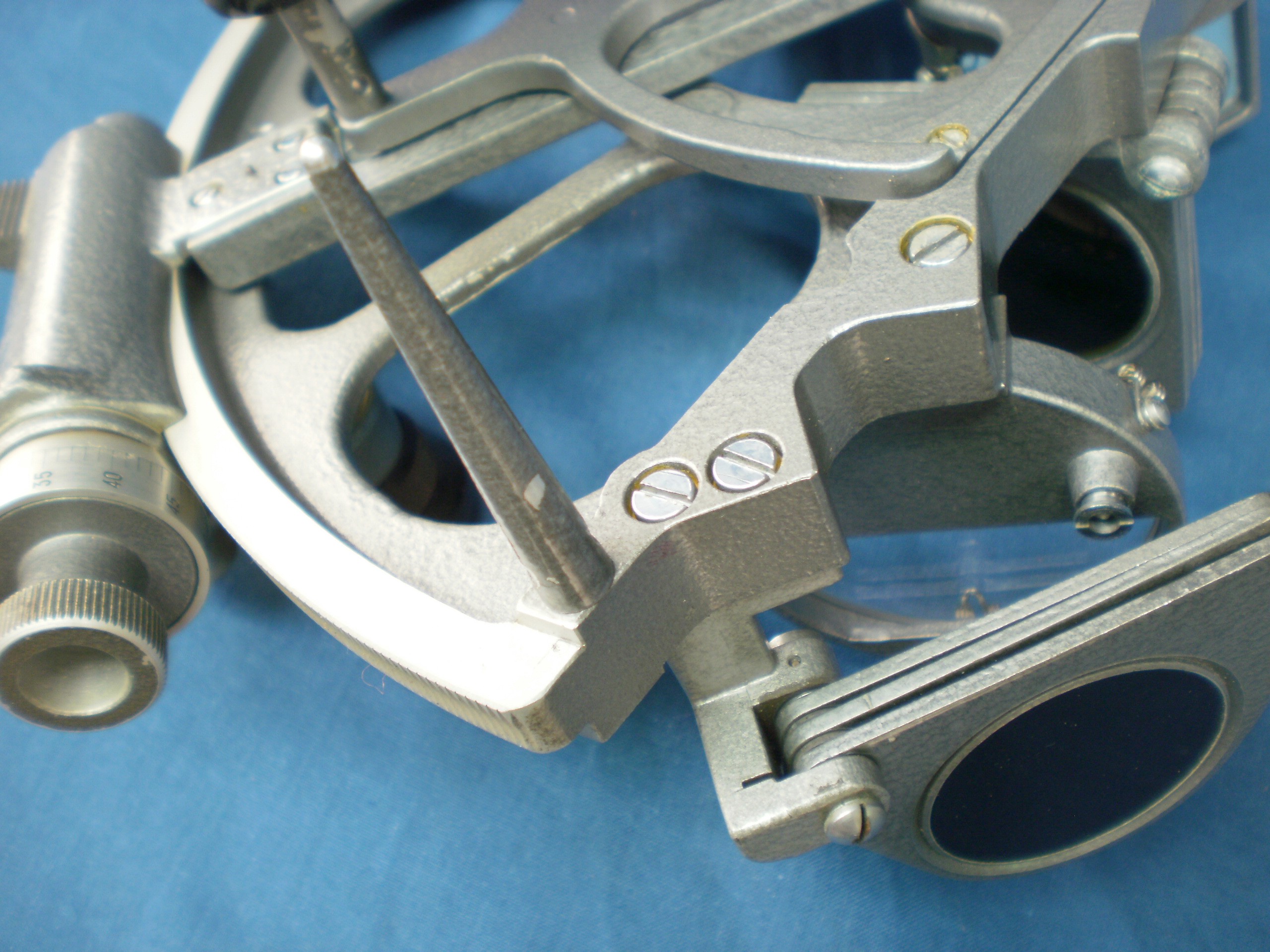
The index mirror sits on a circular table with the journal projecting from its underside. The journal passes through a close-fitting hole in the upper part of the index arm and the latter is secured to the underside of the table by three screws. When I turned my attention to this area, I found that there was a tapered gap between the index arm and the frame of the sextant, indicating that either the bearing was mis-aligned in the frame or that the journal was mis-aligned with the table(Figure 2).

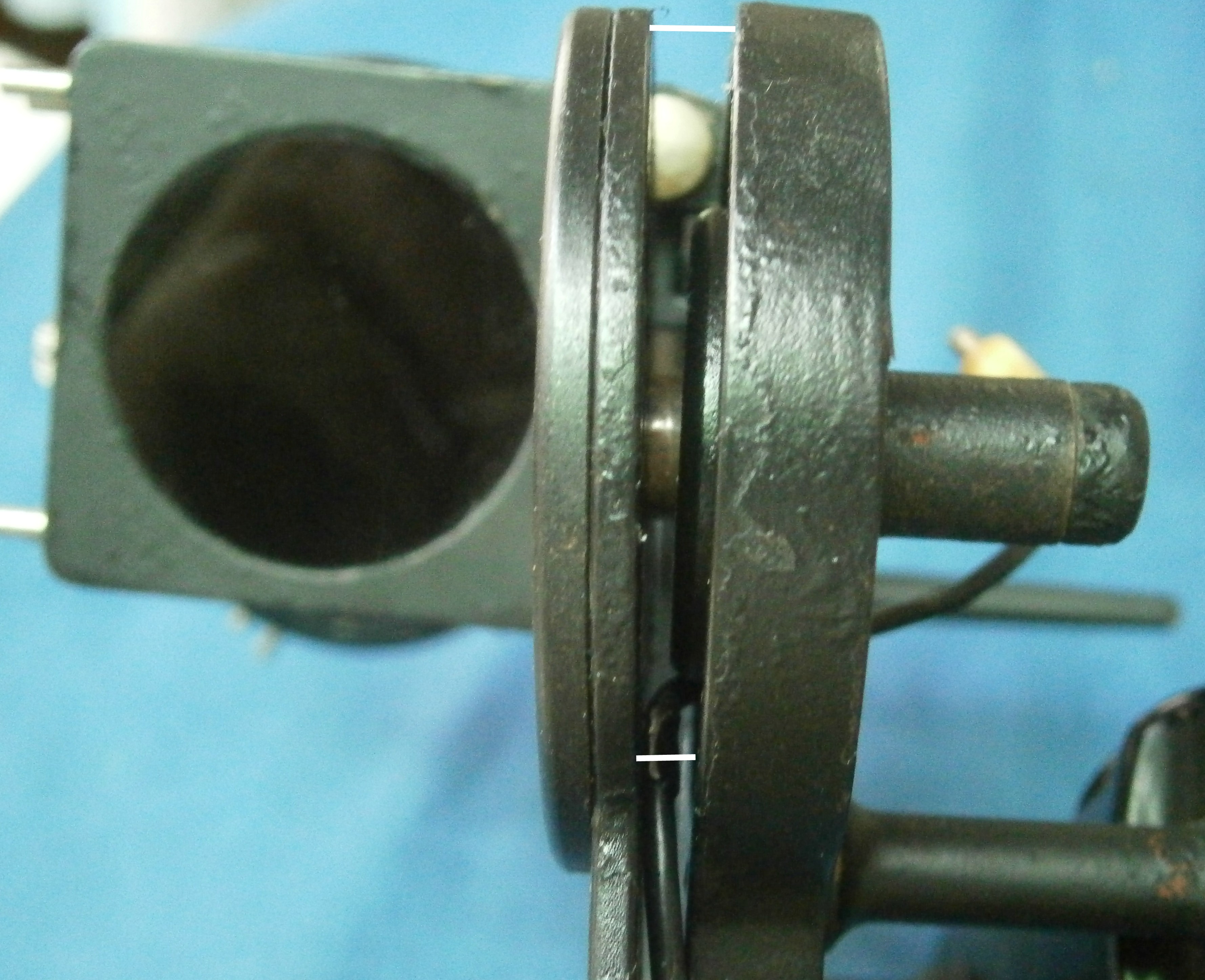
Figure 2: Upper arm and index mirror table.

Figure 3 shows how the alignment of the bearing in the frame is checked in another sextant, using a mandrel that fits closely in the bearing, and a square. As shown the mandrel and therefore the bearing is accurately aligned with the frame., and this was also the case with the sextant being restored.

Figure 3: Upright mandrel.

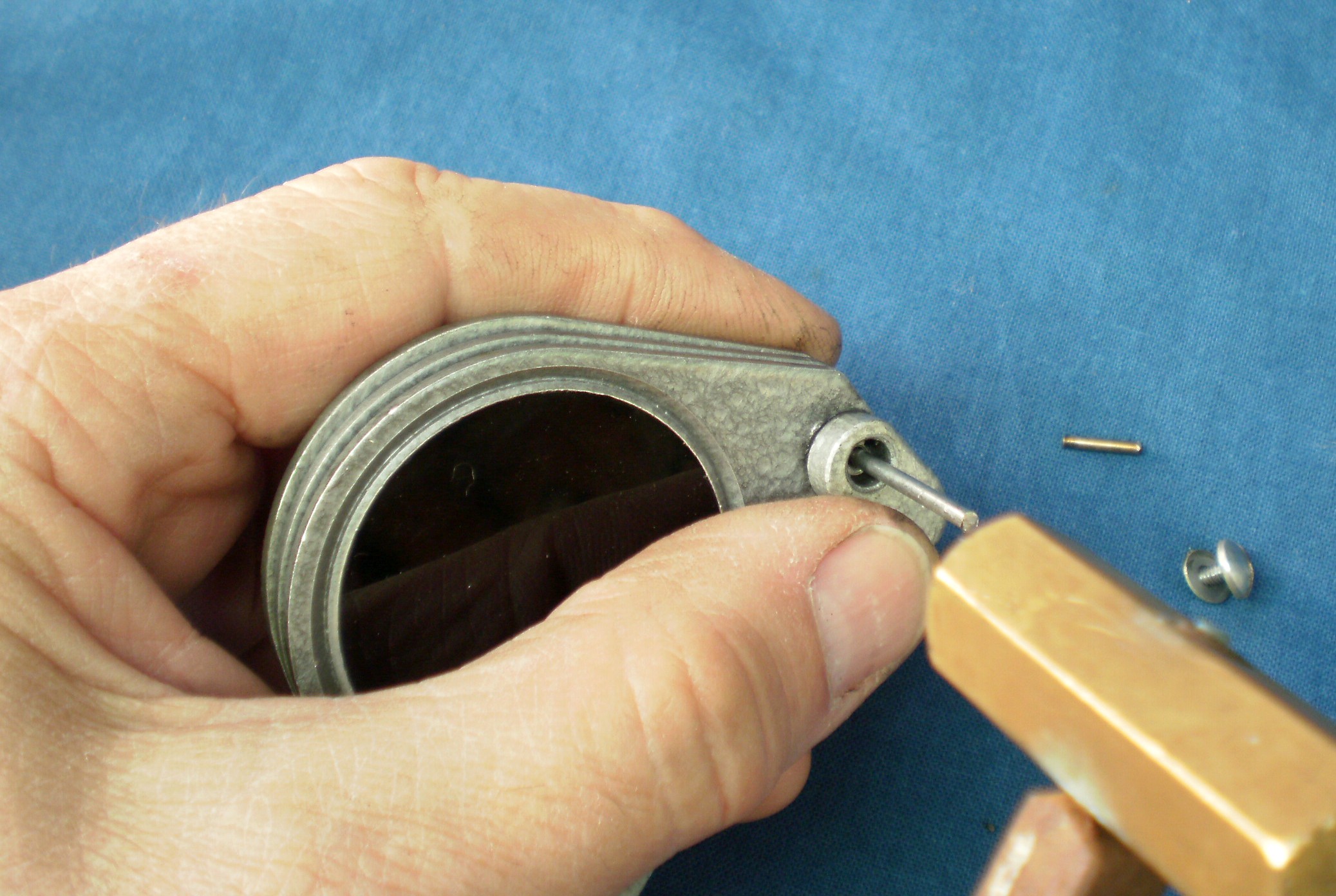
This meant that the journal must have been mis-aligned with the table. Usually, the journal is soldered into the table, but in this instance I could see no joint line and even after heating, there was no sign of a soldered joint giving way, so I surmised that the whole had been machined from a casting. The top of the table would have been turned flat by facing in a lathe and then used as a locating face for turning the tapered journal. By holding the table in a three jaw chuck with the top face hard against the chuck jaws it was possible to see a pronounced wobble as the chuck was turned slowly. Bringing up the tail centre illustrated that there was pronounced run-out of the journal(Figure 4).

Figure 4: Run-out.

The next Figure shows that the total indicated run-out was 1.53 mm.

Figure 4: Total indicated run out.

I asked its owner whether the instrument had perhaps been dropped and he did remember a time when it may have received knocks when he was taking a round of star sights to fix his position, to ensure that he could safely round the North Cape of New Zealand in bad weather. However, It is highly unlikely that the mis-alignment could have been caused by other than shaky inspection or workmanship or both. While it is clear that the index mirror could have been set perpendicular to the plane of the rack at only one position, this would not have introduced a great error(proportional to the cosine of the mis-alignment angle?) at other positions and it may well have allowed the sextant to be certified as “…free from error for practical use.” The variation in effort needed to move the index arm from one end of the arc to the other might well have been unnoticed.

Nevertheless, I elected to make a new part by cutting out a disc of 3 mm brass plate, reaming a 10 mm hole in it and turning and fitting a new journal in it by using a modern industrial adhesive rather than by soldering. In the paragraph preceding Figure 3 in my post of 20 March, 2011 I explain how this is done to ensure proper alignment and the figure of the post illustrates the process. Once fitted, the keepers entered the slot in the limb with correct alignment. Having some time spare, I dug out my sextant calibrator, described in my post of 13 February, 2011 and used it to check the sextant’s errors at 15 degree intervals(Figure 5).

Figure 5: Checking sextant calibration.

The post about the calibrator may tell most people more than they want to know, but put simply, the calibrator rotates one way and the sextant is index mirror rotates the same nominal distance in the opposite direction. The auto-collimator measures any angular difference with a precision of better than an arc second. The calibrator’s errors are known and applied to the result. My friend will I hope be pleased that no error exceeded 12 arc seconds or 0.2 arc minutes and that C Plath’s original claim of being free from error for practical use still holds.

Those with sharp eyes will have noted that a mirror is held against the index mirror with a rubber band. The index and horizon mirrors which I replaced are flat within about one wavelength of green light, quite adequate for use in a sextant. The additional mirror is about five times flatter so that the images seen in the auto-collimator are much sharper and easier to measure.

If you have enjoyed reading this post you may well enjoy reading about the detailed structure of the nautical sextant in “The Nautical Sextant“, available from Paradise Cay Publications, Celestaire and many nautical booksellers. Sticklers for detail may also like my “The Mariner’s Chronometer” available from Amazon. Read about them at http://www.sextantbook.com and http://www.chronometerbook.com


Incorrect assembly of SNO-T shades

6 10 2013

This post is preceded by “Tamaya Collimation Blunder”

In a NavList post for 4th October 2013, Paul Werner wondered whether perhaps the horizon shades of his SNO-T had been incorrectly assembled. There is a method of bringing down the sun to the horizon which involves setting the sextant to zero, pointing the instrument at the sun and then rotating the index arm while keeping the reflected sun in sight until the horizon appears. I find it a very easy method with the sun and a nearly essential one for star observations. Paul was troubled by a crescent of direct sunlight getting into the field of view at the lower left side of the field of view beneath the horizon shades, and was worried that his eyesight might thereby be damaged. I had noticed the effect too but had thought little about it, probably because I had got into the habit of keeping the images well into the right of the field of view.

When I trawled through photographs on the internet of SNO-T sextants, they were all assembled just like Paul’s sextant and Alex Eremenko reported that his sextant had arrived in the factory wrappings in exactly the same way (Figure 1). It scarcely seemed possible that all the SNO-T sextants I could find had been assembled incorrectly, but when I remounted the shades, supposedly upside down, it was immediately obvious that this was in fact the correct way, as Paul’s problem had disappeared. There was still the possibility of direct light getting between the bottom of the index shades and the top of the horizon mirror, but this only occurred with the top shade on its own, which in my sextant is the lightest (numbered “4”) and therefore least likely to be used on its own for sun sights.

Figure 1: Shades as fitted.

Figure 1: Horizon shades as fitted.

For those SNO-T sextant owners who wish to remount their horizon shades, this is how to do it. First remove the shades assembly from the frame by releasing two 4 mm screws (Figure 2). You can enlarge all the photos by clicking on them. Return to the text by clicking on the back arrow at top left.

Figure 2: Remove 2 screws.

Figure 2: Remove 2 screws.

The small end of a  taper pin can be seen in the far bearing for the shades mounting pin in Figure 2. It prevents the mounting pin from rotating and must now be drifted out. This is not altogether an easy task, as the small end of the pin cannot be accessed from directly above because the base of the bracket is in the way, and so the drift has to be struck at an angle. It is very important that the bearing is supported as close beneath the large end of the taper pin as possible, since aluminium alloy castings tend to give no warning that they are about to break if stressed unsupported. Figure 3 shows the casting supported at both ends by the jaws of a vice. The adjusting screw should also be slackened off a few turns. A short piece of an old bicycle spoke ground down to size makes a good drift and you may have to give the short end of the taper pin quite a hard blow to get the pin moving. Once it does so and there is something of the large end to grip with a pair of pliers, the removal can be completed with a twisting pull. If the taper pin will not move after having been struck as hard as you dare, apply some releasing compound and try again the next day.

Figure 3: Drift out taper pin.

Figure 3: Drift out taper pin.

The mounting pin then has to be drifted out with a drift that fits down the hole for the screw (Figure 4). Do not be tempted simply to loosen the screw and hit its head. This is a good way to bend the rather narrow screw, which then tends to break off when it is re-straightened. Experience is a good teacher to those who listen.

Figure 4: Push out mounting pin with drift.

Figure 4: Push out mounting pin with drift.

The assembly can now be taken completely apart for cleaning (Figure5). Note that the washers that fit between the shades have internal keys that fit into a longitudinal keyway machined into the mounting pin, so that they cannot rotate. This prevents rotational forces from being transmitted from a shade to its neighbours, so that they can all be rotated independently.

Figure 5: Shades assembly exploded.

Figure 5: Shades assembly exploded.

When re-assembling, I find it is helpful to apply a smear of waterproof grease to the mounting pin and a somewhat thicker smear to each side of the washers. This seems to help them to stay together. Mount the shades and their washers on to the mounting pin and manoeuvre the edges of the shades and washers between the uprights of the brackets (Figure 6).

Figure 6: Placing shades between uprights.

Figure 6: Placing shades between uprights.

Holding the sandwich of shades and washers firmly together, slide out the mounting pin and slide the sandwich into line with the holes in the uprights. Then reinsert the pin (from the correct end!) and wangle it through the sandwich and out the other side (Figure 7).

Figure 7: Shades and mounting pin in place

Figure 7: Shades and mounting pin in place

The hole in the mounting pin is then lined up with the holes in the upright and a new, greased taper pin inserted (Figure 8). You can of course use the old pin, but if you use a new one, you can leave it as long as you like for easier removal, which is especially useful if you find you have remounted the shades just as they were before…

Figure 8: New taper pin in place.

Figure 8: New taper pin in place.

Figure 9 shows the shades remounted on the sextant in their new, improved, correct orientation. It is now obvious that direct rays of the sun can no longer reach the telescope either above or below the shades.

Figure 9: Shades now correctly mounted.

Figure 9: Shades now correctly mounted.

If you have enjoyed reading this post, you will I am sure enjoy reading my books, “The Nautical Sextant” and “The Mariner’s Chronometer”. You can read what others think of them by logging on to Amazon and looking for the titles under “books”.


Tamaya Collimation Blunder

2 09 2011

A comment in February this year on NavList about the Tamya Regulus sextant set me wondering, as the Tamaya sextants I have examined seem to be well-constructed. The writer commented on problems people had with the Regulus pattern at a nautical training establishment in the 1970s, so when a Tamya Regulus II recently came into my hands for overhaul and restoration work, I looked at it with unusual care. It seems to have been well-constructed, following the pattern set by C. Plath many years ago. It has an aluminium alloy frame with bronze rack, large mirrors and shades to match,  an adequate 3 x 40 Galilean telescope, a very good scale illumination system and a switch that is accessible and easy to overhaul. I was as puzzled by the adverse comments about the instrument by the time I had put it together again – until I came to align the telescope.

The telescopes of many sextants can be collimated, that is to say, the axis of the telescope can be adjusted so that it lies parallel to the plane of the arc. A lot of modern sextants do not have this feature, as the effects of mis-collimation have relatively little effect on the accuracy of observations, unless the observed angle is high or the angle of misalignment is great. For example, if the observed angle is 60 degrees and the misalignment is 55 minute, the error will be only half a minute. In fact, the error is proportional to the tangent of half the angle of observation and to the square of  the angle of misalignment in minutes.

Usually, the telescope screws into a flanged ring, and two screws allow the ring to be rocked about the rising piece, with two cone-ended screws for an axis, as shown in Figure 1.

Figure 1 : Collimating rising piece exploded

After I had adjusted the mirrors, I moved on to check the collimation of the telscope and to my surprise found that it was not possible to do so, as the adjusting screws rocked the telescope up and down, parallel to the plane of the instrument, rather than at right angles to it. Figure 2 shows at the top the rising piece as I found it and beneath, the rising piece as it should have been.

This led me to look at another sextant of identical construction and undoubtedly made by Tamaya though bearing another name. It too had the same mistaken construction as did one currently for sale on e-bay and named Tama-Sokki. I promptly re-arranged matters by plugging the tapped holes for the adjusting screws, tapping holes for the adjusting screws where the seats for the cone-ended screws had been and rotating the telescope ring through 90 degrees (Figure 2, lower half). This modification requires only two grub screws and can be done with hand tools alone. One can only guess how Tamaya overlooked this blunder. Probably someone in the drawing office got a bit confused, noone in production noticed the error and, it seems, neither did a great many sellers and users of the instruments. My impression is that many users never attempt to check for anything other than index error. There is something to be said for noting small index errors rather than constantly fiddling with the adjusting screws, but personally I would always check the adjustment of any instrument that I was going to rely upon, correct large side and index errors and at least glance at the telescope to see that it had no obvious lean to or away from the frame. Any good book on the sextant (like The Nautical Sextant) and many manuals of navigation will tell you how then to adjust the telescope collimation.