Previous posts in this category include: “A Half-size Sextant by Lefebvre-Poulin”,
Figures may be enlarged by right clicking on them. Return to the text by using the back arrow.
A rather dusty and neglected little French sextant came into my hands a few weeks ago. The kinship of French sextants is quite difficult to sort out. This one bore a label in which the name of A Hurlimann is given prominence and the names of his successors, Ponthus and Therode, are given less prominence (Figure 1). The limb is engraved in copperplate Lorieux, A Hurlimann, succr (successor) à Paris.
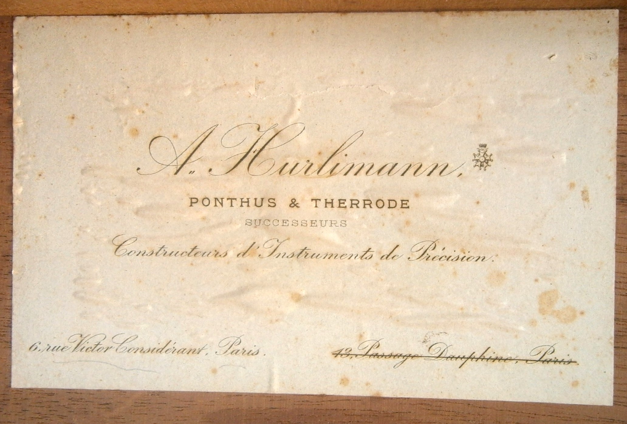
Figure 1 : Label in lid of case.
A. Hurlimann succeeded a distinguished line of French instrument makers. Two pupils of the renowned Henri Gambey founded a firm in 1845. Possibly both originally named Schwartz (Black), they were known as Lenoir (Black) and Lorieux, and managed by Lorieux and then Hurlimann. In 1900 they were succeeded by Ponthus and Therode. At the turn of the century in about 1902 the firm moved from 43, Passage Dauphine, Paris, to 6 rue Victor Considerant. It was then taken over by Albert Lepetit , possibly in 1914, and moved to Montrouge at 204 avenue Marx Dormoy, eventually passing into the hands of Roger Poulin in about 1950. Thus, I surmise that the sextant dates from between 1902 and 1914.
Figure 2 shows the instrument in its case as received. There is a large shrinkage crack in the lid and floor. Not clearly visible are a Keplerian telescope of about 6 power in a pocket at the front of the case and a screwdriver at the back. The label in the lid counsels against using alcohol to clean the instrument, suggesting that it is painted with a shellac-based lacquer (which dissolves in alcohol).
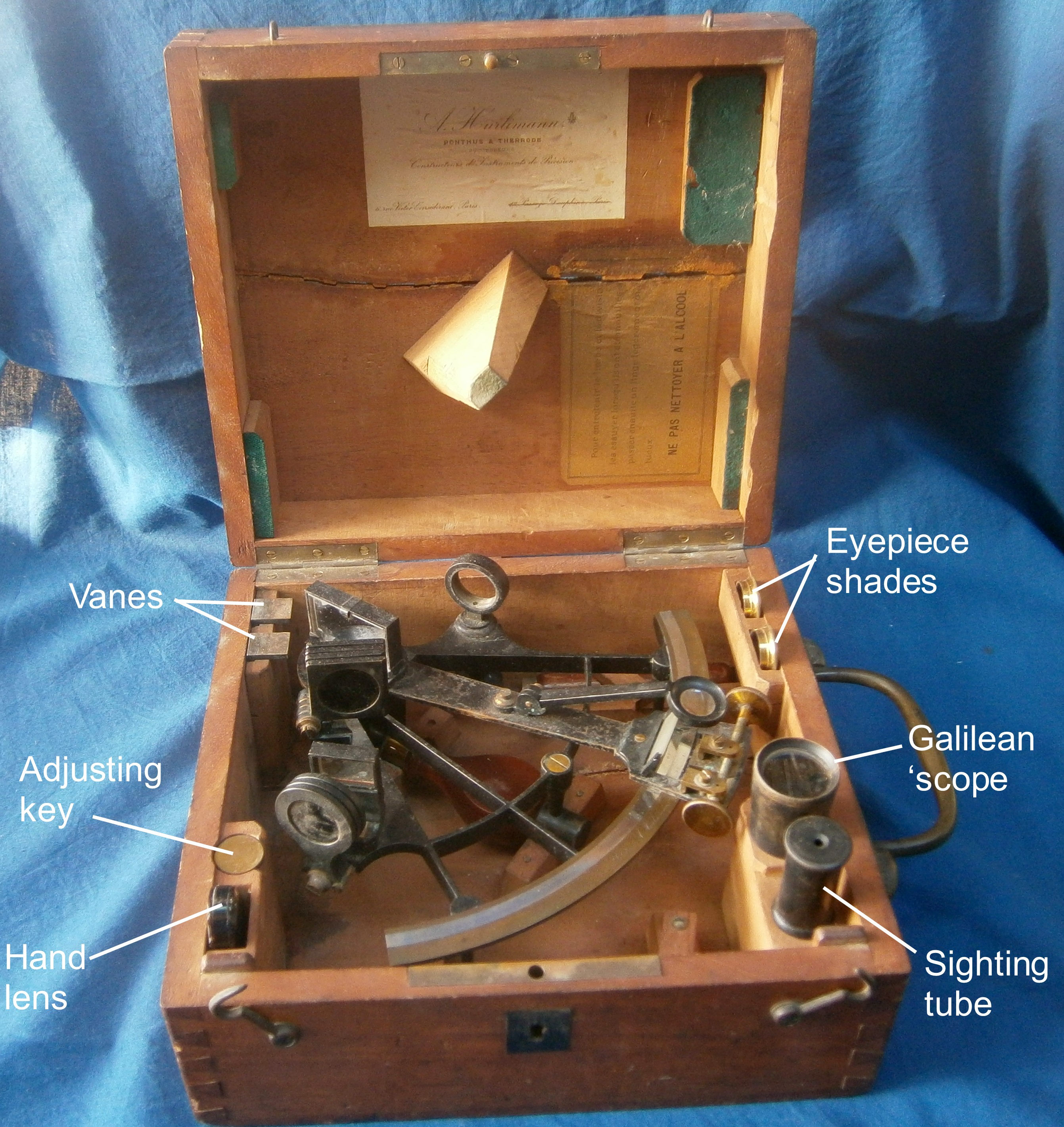
Figure 2: Sextant as received.
The frame is a bronze casting with inlaid silver arc, beautifully finished and otherwise unremarkable except for its relatively small radius for the time, of only 142 mm. The arc is divided to 20 minutes and the vernier reads to a realistic 30 seconds. The divisions are crisp and the numerals are hand engraved in italics. A more usual radius for vernier sextants is about 180 mm and many of these instruments have verniers divided to 10 seconds, though it is usually quite impossible in these cases to say with certainty which pair of lines coincide.
There are two main areas of interest in the design: a) the mirror adjustments are complicated, compared to what we may think of as the modern method of springs on the front of the mirrors opposing the action of screws behind the mirror (in fact this dates from the 18th century and was invented by John Dolland); and b) the mode of mounting of the tangent screw, which seems to have had a German influence, as it is also seen in vernier sextants made by Frederick Ernest Brandis, a German immigrant to the New York in 1858.
The index mirror is held against the upright of a bracket by means of a clamp whose clamping screw bears against the back of the upright as shown in Figure 3 and Figure 4.

Figure 3: Front of index mirror clamp.

Figure 4: Index mirror in place.
The mirror is adjusted for perpendicularity by rocking the whole bracket on the two radiused front feet by means of an adjusting screw held captive in the horizontal part of the bracket and engaging with a threaded hole in the top of the index arm (Figure 5). The screw can be locked by tightening the screws that pass through the brass clamp bar that holds the screw captive. An earlier (and simpler) method was to have the hole in the foot tapped for a screw, the end of which simply bore on the face of the index arm, though there was a tendency for the thread to strip in clumsy hands.
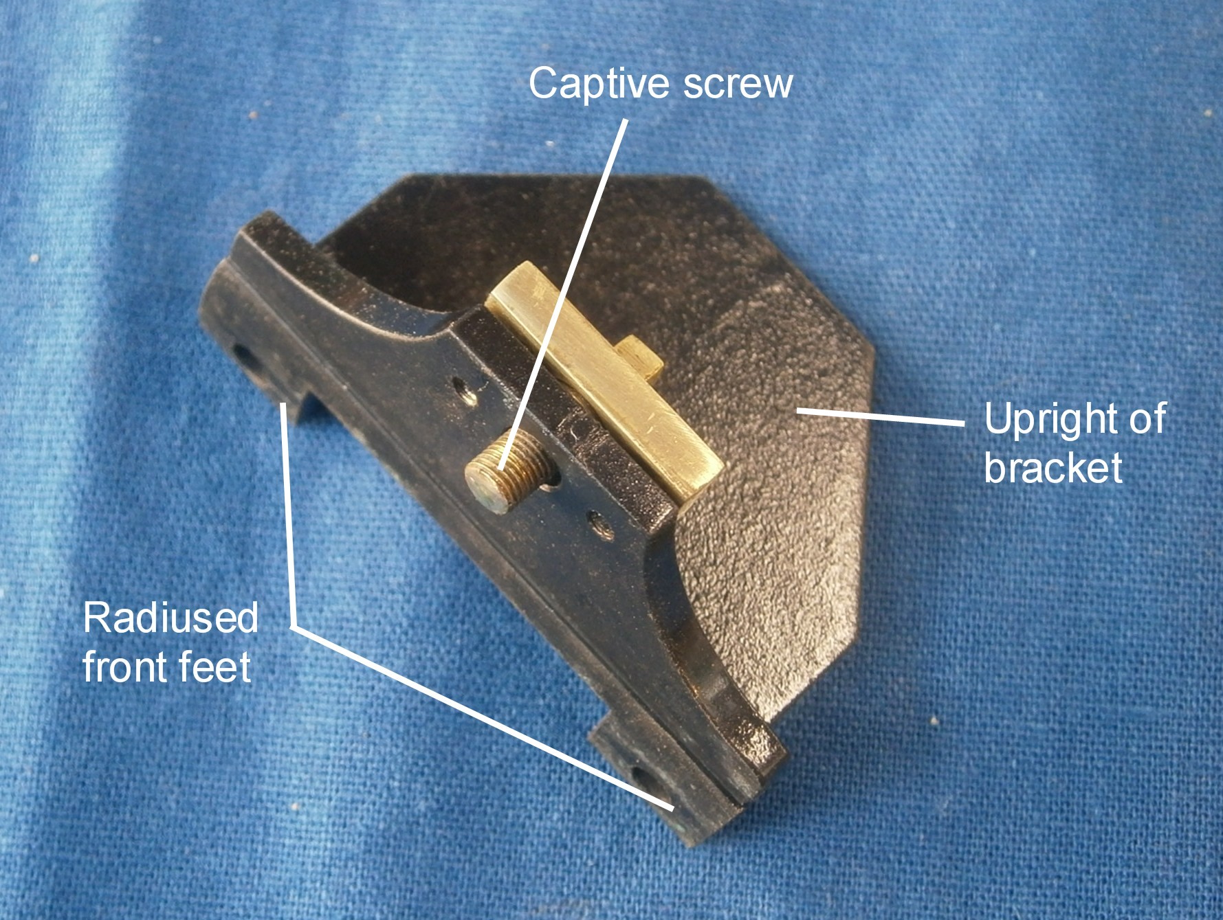
Figure 5: Index mirror bracket with screw in place.
The horizon mirror adjustment system is even more complex. A large cylindrical boss on the underside of the bracket (Figure 6) passes through a hole in the sextant frame and is secured by a large brass locking screw and washer (Figure 7). A screw held captive in the frame enters the threaded hole in the tongue and rotates the mirror to correct for index error (Figure 8). This movement is locked by means of the knurled clamp screw behind the frame, seen in Figures 7 and 8.
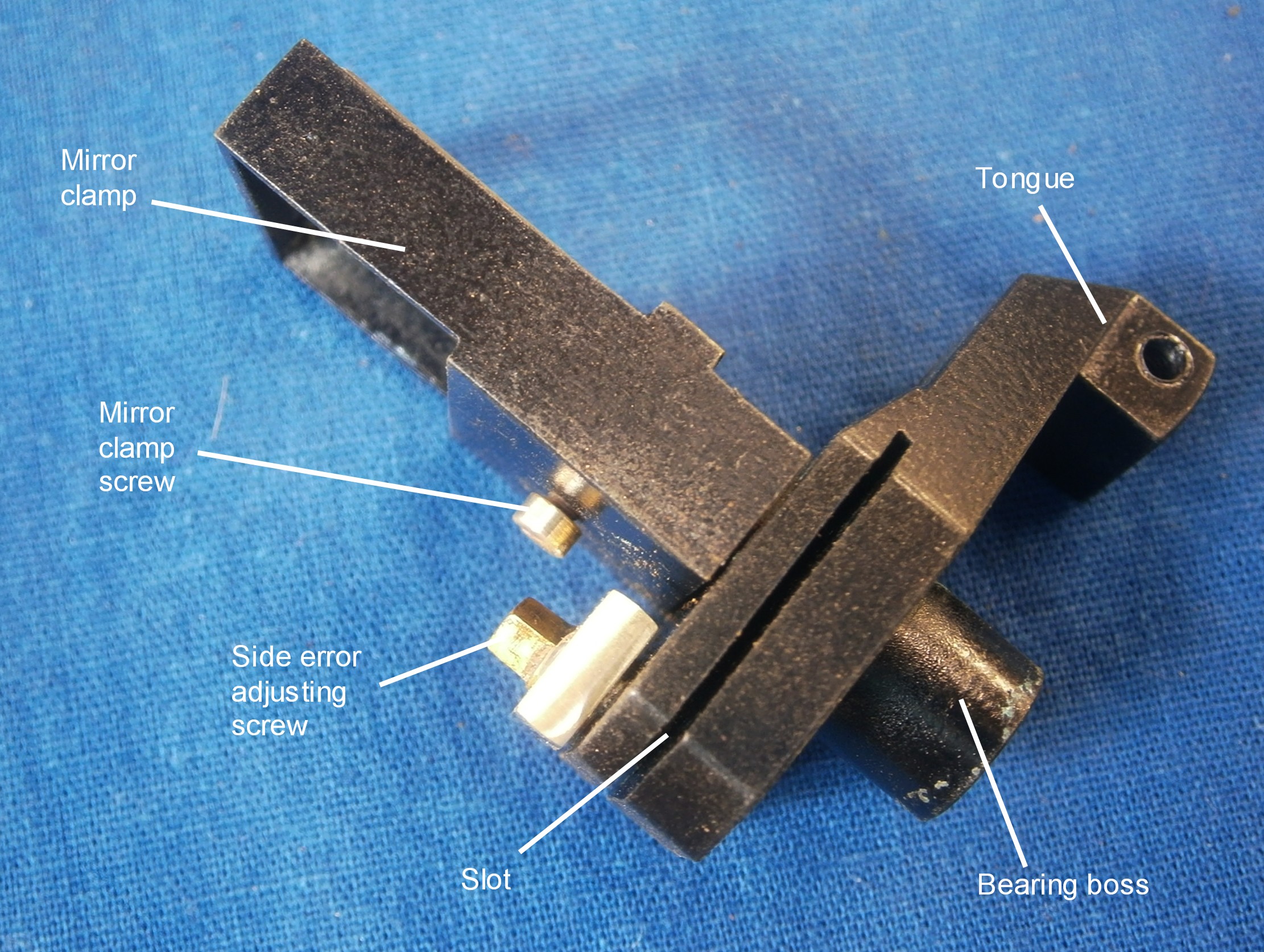
Figure 6: Horizon mirror bracket and clamp.
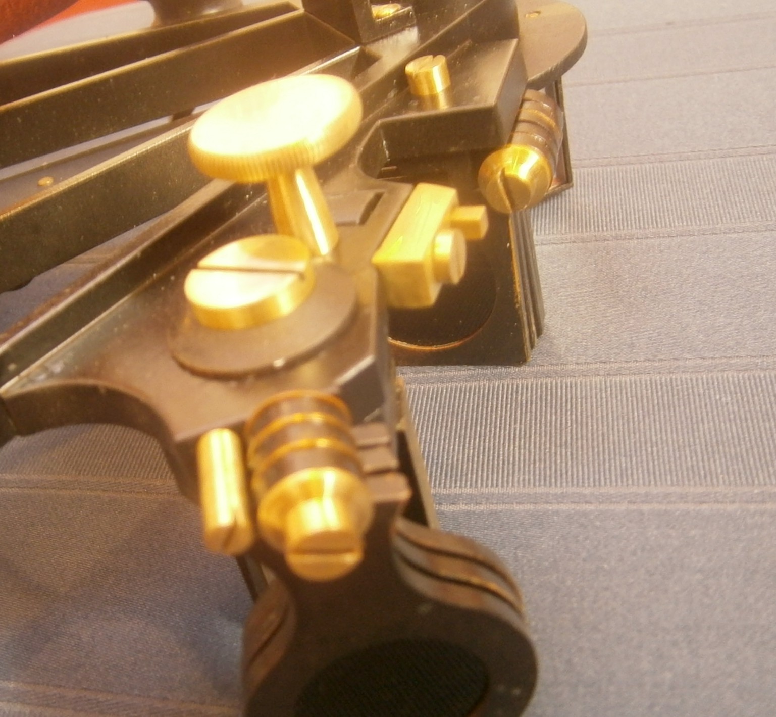
Figure 7: Horizon mirror locking screws.
Side error is taken care of by a similar captive screw that opens or closes the slot in the base of the bracket, as seen in Figure 6 and 8. These adjustments are easy to use and effective, but are at the expense of a good deal of complication.

Figure 8: General view of horizon mirror adjustments.
The telescope mounting again achieves a good result at the expense of complexity (Figure 9). The rising piece is triangular in section and is close-fitting in a triangular hole in a bracket that passes through a hole in the telescope frame and which is secured by a large knurled nut. A countersunk screw passes through the frame into the bracket to secure it against rotation. A large knurled adjusting thumb screw is held captive in the bracket and its thread passes up the middle of the rising piece to make it rise or fall.

Figure 9: Mounting of telescope rising piece.
Figure 10 shows the mounting exploded.
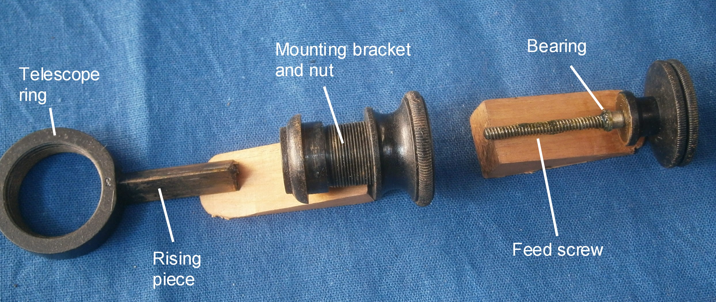
Figure 10: Exploded view of telescope mounting.
The tangent screw follows F E Brandis’ practice quite closely (or vice-versa). It has a knurled knob on each end and runs in a spherical bearing at the front end. The threaded part passes through a spherical nut which is held captive in the sliding block by a cap and prevented from rotating by the slender boss on its underside, that passes into a hole in the spherical seat on the face of the sliding block (Figure 11).

Figure 11: General view of tangent screw mechanism.
Figure 11 shows the tangent screw bearing exploded and it can also be seen that the nut cap is a similar device to the bearing cap.
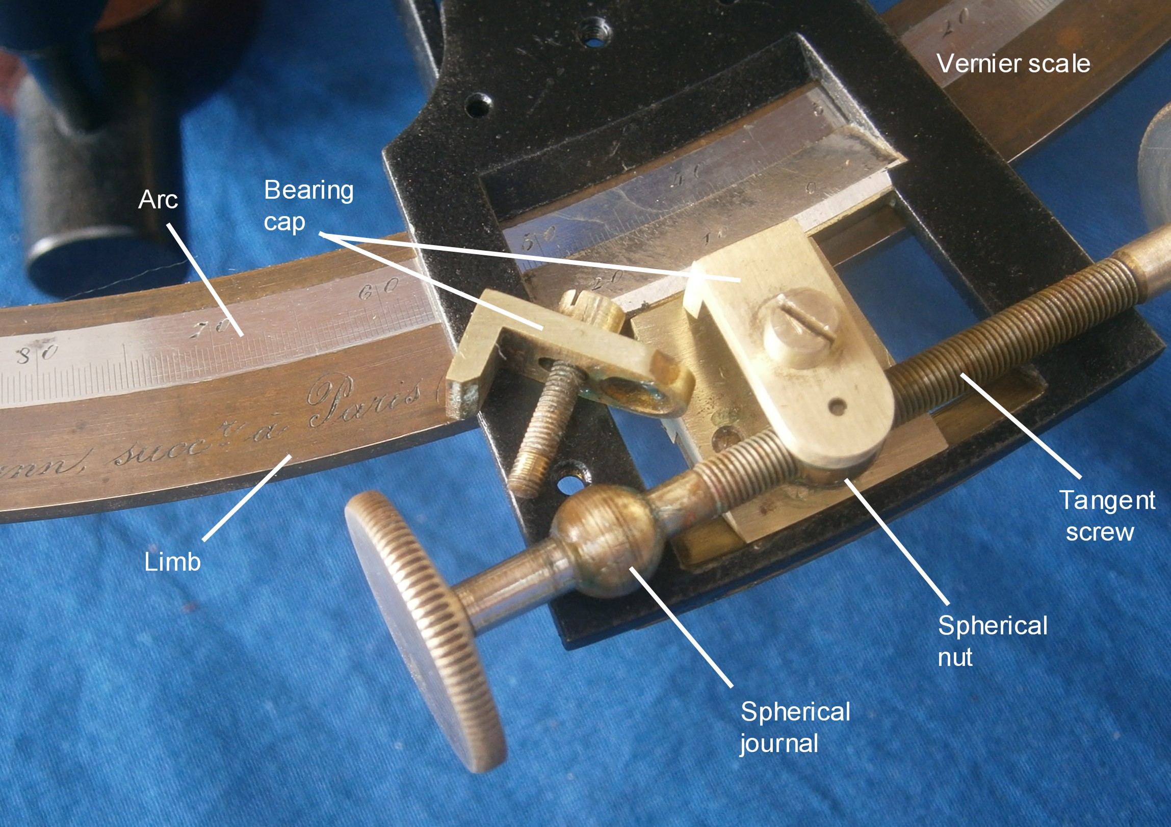
Figure 12: Tangent screw bearing.
The sliding block is held in the rectangular window cut into the expanded part of the index arm by a leaf spring and a clamp spring. When the clamp is tightened, the block can no longer slide over the limb, so that when the tangent screw is rotated it is the index arm that moves. Thus, although I have named the part the sliding block (since no one else seems to have troubled to give it a name) in truth it is the index arm expansion that does the sliding.

Figure 13: Underside of sliding block and clamp.
The shades mountings are unremarkable in design (see Figure 7) except that they have no provision for isolating the movement of one shade from the next by means of, for example, keyed separating washers. Friction is provided by Belleville washers, patented in 1867 by Julien Belleville, a Frenchman.
The telescope kit comprises the usual “zero magnification” sighting tube, a 3 x 26 mm Galilean “star” and a 6 x 15 Keplerian or “inverting” telescope (Figure 14), supplemented by two eyepiece shades of more or less equal density though of slightly different colours (neutral and deep orange).

Figure 14: Sighting devices.
The case (Figure 15) is of a light coloured wood with a grain similar to that of mahogany, with dovetailed corners, and both top and bottom were glued and nailed on with steel pins. I find it strange that a few francs were saved by using steel instead of brass pins or, better, brass screws, given that the whole instrument probably cost several months salary for a merchant officer of the time. On the other hand, the brass handle seems on the heavy side for the neat little case into which all the parts fit snugly, perhaps too snugly, and the instrument is held in a pair of felt-lined pockets by a pillar in the lid which passes through the frame and sits on the sextant handle (Figure 2, above). The latter is of the traditional pear shape. The hinges and hooks are of brass and there is a brass lock with ebony escutcheon.

Figure 15: Case exterior.
It was possible to remove both top and bottom for re-gluing and the crack in the bottom was simply closed up, leaving a minor cosmetic deficit at the back of the case. The crack in the top was much wider and I dealt with it after re-gluing and nailing by filling it with epoxy cement and adding a layer of coloured filler above and below. It was not possible to save the label with its cleaning advice and I replaced it by a modern one using a matching typeface and lay out. Figure 16 shows the final result of the restoration of sextant and case.

Figure 16: Restored instrument and case.
Post script: Come to think of it, the card pasted inside the lid, suggests a time of sale after 1902, but the inscription on the limb of the sextant itself suggests that it was made before the Pontus and Therode take-over.

You must be logged in to post a comment.