I wrote about a Hughes and Son Admiralty pattern vernier sextant on 23rd June 2011, concentrating on its telescopes, its rising piece for the latter and its sealed mirrors. Recently, I acquired an Admiralty pattern micrometer sextant, probably part of a batch ordered in the closing days of WWII. The main difference is in the micrometer mechanism while the index arm bearing, mirrors, shades and telescopes are essentially the same as in the vernier sextant, certified in March of 1939, so I will not cover that ground again. Figure 1 shows the instrument as advertised by the seller, who seems to have photographed it through a light green filter. This explains the green cast to the blue-grey paint (I have removed the bright green background).
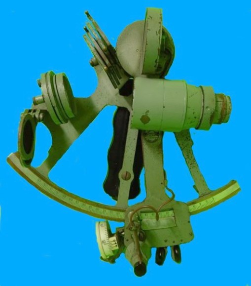
Figure 1: As bought.
The sextant was in a rather grubby condition, with paint beginning to perish and flake off in parts. I suspect it had been well-used, rather than spending nearly all its life in a cupboard.
Figure 2 shows the front view after a complete strip-down and restoration. In it I have labelled the main parts of a micrometer section for the benefit of newcomers to my site, and those who may not yet have purchased my book “The Nautical Sextant”, which looks in great detail at the structure of these instruments.
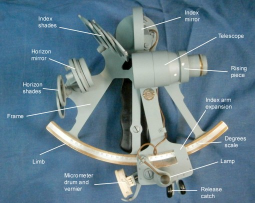
Figure 2: Front view of restored sextant.
Figure 3 shows the rear (or right hand side when in use). Here it is possible to see why this sextant, weighing in at 2.05 kg (4.52 lb) is so heavy. The cast bronze frame is very heavily ribbed compared to most other sextants, and features like the rising piece, the Index arm bearing cover and the complex arrangements for sealing the mirrors have all added to the weight. Earlier Hughes and Son instruments with scale lighting made the battery handle out of wood, but this one is of molded Bakelite with a brass battery cover. Happily, it contained no batteries nor signs of corrosion.

Figure 3: Rear view of restored sextant.
Figure 4 shows details of the micrometer mechanism. The worm engages with the rack, which is cut into the edge of the limb. The rack is in essence a segment of a worm wheel having 720 teeth. Also cut into the edge of the limb is a groove which accepts the free edge of the two keepers. These prevent the index arm from lifting off the limb.

Figure 4: Details of micrometer mechanism.
The axial pre-load spring, which is shown out of place, is U-shaped with one upright of the U being forked to embrace the worm shaft and press on the flange immediately to the left of the thrust bearing. The worm shaft inside the bearing is conical, so it aligns the shaft axially and radially with a further bearing providing more radial guidance. This spring is a simpler solution to providing thrust pre-load than the more complicated systems used by Hughes and other makers prior to WW II.
The worm is held in engagement with the rack by a beryllium-copper radial pre-load spring. A simple cam bears on an arm extending from the swing arm on which the bearings and worm are mounted. When the release catch is operated, the cam causes the swing arm to rotate around a substantial bearing and the worm disengages so that the index arm can be swung rapidly to a new position. When the release catch is let go, the spring swings the worm back into engagement with the rack and rotation of the micrometer drum provides fine adjustment.
There is a guard extending from the swing arm to provide some protection to the micrometer drum and the worm shaft. The shaft is often bent when a sextant is dropped or knocked and, as replacement parts have long been unobtainable, a whole worm and shaft have to be made. See for example “A Worm Turns” on this site on 23rd June 2011. The worm itself receives some protection from a sheet metal cover, seen in Figure 3.
Figure 4 shows the front of the index arm in the area of the worm. The screw that secures the axis about which the swing arm rotates has been removed to show a washer that is prevented from rotating by two pins into the swing arm, so that the screw can be adjusted to remove end shake in the bearing, while preventing movement of the swing arm from loosening or tightening the screw.
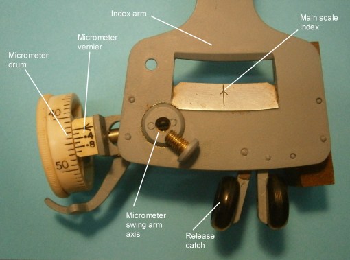
Figure 5: More micrometer details.
There seems to be little point in providing a vernier to the micrometer, as the racks of this era often had errors in excess of 0.5 minutes and in any case, observation errors due to uncertainties about refraction and dip would often swamp instrument errors. Most makers after WWII abandoned micrometer verniers, but some were still made, presumably to satisfy conservative mariners and military procurement officers.
This instrument was provided with a fairly comprehensive kit of telescope and tools, shown in Figure 6. Most mariners probably never used anything other than the Galilean (“star”) telescopes in the 20th century. The higher powered ones were probably used mainly for artificial horizon shots in ports of known longitude to correct chronometers. This was made obsolete by the advent of radio time signals, but Tamaya in particular continued to provide them to the very end of sextant manufacture.
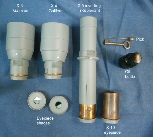
Figure 7: Ancillaries.
The eyepiece shades are useful for finding the index or zero error of the sextant by looking at the sun or moon, but again, most mariners would simply have used combinations of horizon and index shades, or used the horizon to avoid strain on the neck from looking up at the sun.
A very useful feature of the Galilean telescopes is the provision of hoods to prevent glare from around the horizon mirror reaching the eye, as the hood limits the field of view to the mirror alone (Figure 8).
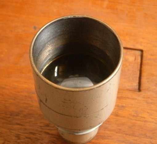
Figure 8: Telescope hood.
Figure 9 shows the sextant and its telescopes etc. in its fine mahogany case. As usual from about 1900 onwards, the corners have box comb joints. In all Hughes and Son sextants, the handle is on the right hand side, to avoid setting down the box on its hinges.
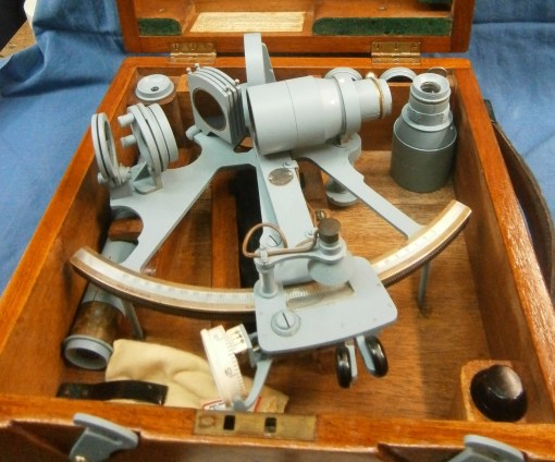
Figure 9: The sextant in its case.
Figure 10, shows the case standing on its left hand side. This, together with the hook latches which always face to the left, so that they tend to remain latched in the carrying position, identifies the sextant as a Hughes and Son, if it were not obvious from the circular “Husun” emblem attached to the index arm.
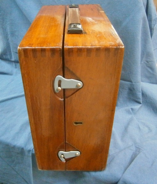
Figure 10: Hook latches in closed position.
If you have enjoyed reading this account, you will find much more of the same in my book “The Nautical Sextant”, but do not expect to find anything about in it about navigation. It is about the structure of the sextant.You can find plenty of positive reviews of the book on the amazon.com web site.

You must be logged in to post a comment.