A few months ago I was entrusted with a variety of antique sextants to restore and, while restorations proceeded slowly on account of family infirmity, writing about the restorations has proceeded even more slowly. However, now that the infirmity has been mitigated to a large extent by the skills of an orthopaedic surgeon, I expect to have a little more time to myself in order to catch up.
I started with a reflecting circle named “Lorieux. Lepetit sucr. Montrouge”, meaning “successors to Lorieux and LePetit at Montrouge. Two pupils of the renowned Henri Gambey founded a firm in 1845. Possibly both originally named Schwartz (Black), they were known as Lenoir (Black) and Lorieux, and managed by Lorieux and then Hurlimann. In 1900 they were succeeded by Ponthus and Therode. At the turn of the century in about 1902 the firm moved from 43, Passage Dauphine, Paris, to 6 rue Victor Considerant. It was then taken over by Albert Lepetit , possibly in 1914, and moved to Montrouge at 204 avenue Marx Dormoy, eventually passing into the hands of Roger Poulin in about 1950.
Even if the circle had borne no name, it would have been easy to identify the instrument as French because of the distinctive way the tangent screw and mirror brackets were constructed and it is on these that I will concentrate in the following description.
While the French had somewhat of a preference for circles over sextants in the nineteenth century, by the end of the century, reflecting circles were used mainly in surveying and hydrography, as they are awkward to handle as nautical sextants. Their main advantage is in being able to measure large angles. This instrument (Figure 1) measures angles up to about 240 degrees, after which the view becomes rather narrow. It is however calibrated from zero to 180 degrees to the left and zero the 140 degrees to the right, the latter when held as a sextant with the frame vertical. The vernier has a central zero and is divided to 30 minutes each side.
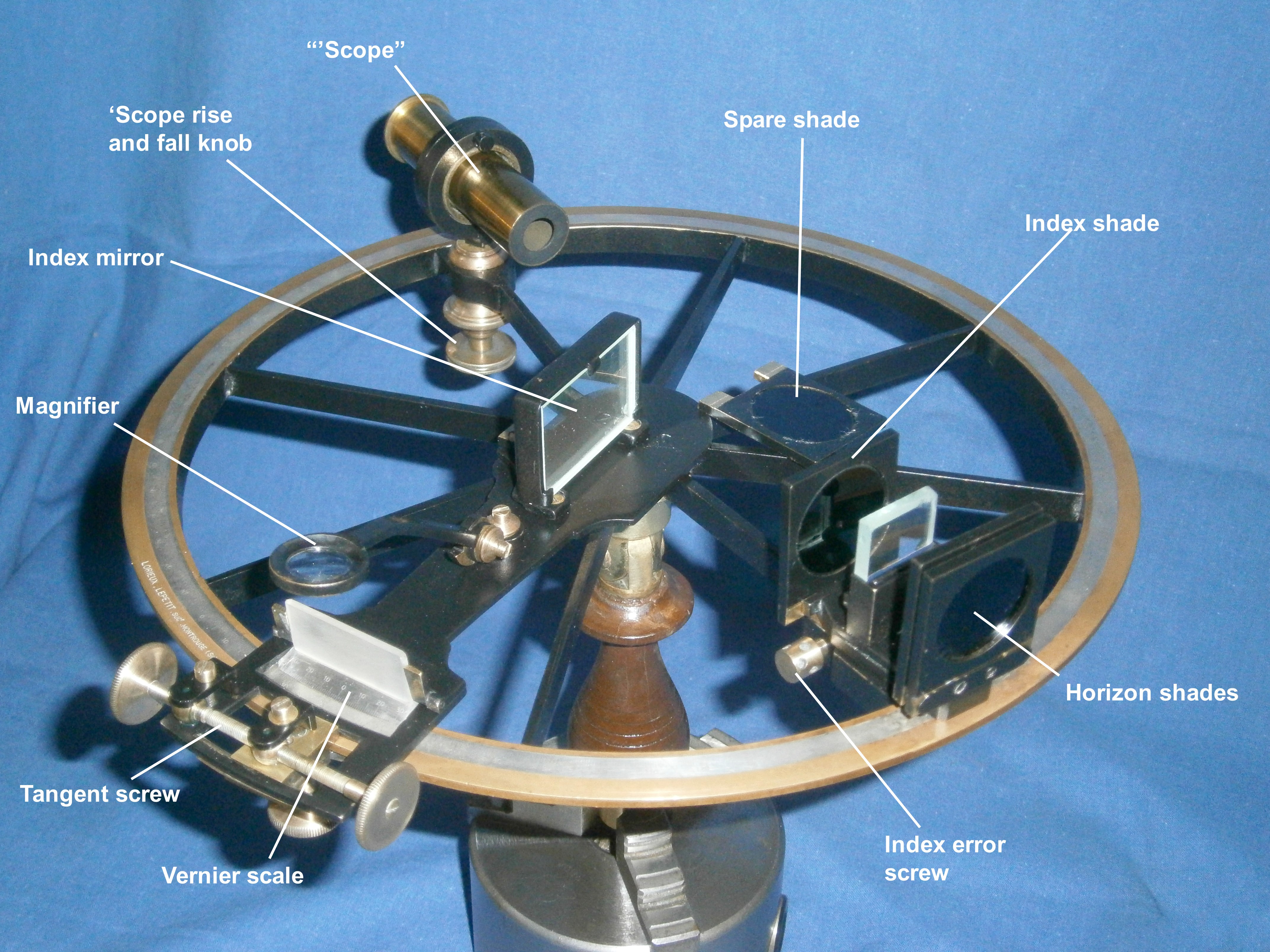
The circular bronze frame of about 125 mm radius has eight substantial ribs supporting a circle into which is inlaid a silver arc divided to half minutes. The index arm is similar to that of a sextant, with a normal tapered bearing whose end is concealed inside the screw-on ferrule of the handle (Figure 2). The handle folds down for storage.

The tangent screw arrangement is shown in Figure 3.

A block slides in a cut-out in the lower end of the index arm, retained by a leaf spring which will be seen in Figure 4. The tangent screw passes through a split nut and is held captive in its tapered bearing by an adjustable knob mounted on a square and retained by a screw. The bearing is held in a depression in the index arm by a keeper, while the nut is held on the sliding block. Although I have called it a sliding block (because no one else seems to have named it), when it is clamped to the edge of the circle, it is the index arm that slides when the tangent screw is rotated, allowing fine adjustment. The clamping arrangement is shown in Figure 4. When the clamping knob is released, a leaf spring holds the index arm against the face of the frame, while allowing rapid adjustment of the position of the index arm.

The scales may be read using a plano-convex magnifying lens of about 35 mm focal length. The arm of the magnifier is attached to the index arm by a complex little bracket that allows the lens to by swung from side to side and up and down (Figure 5)

The index mirror bracket is attached by two screws at the front to the index arm. At the rear a screw is held captive in the bracket and its threaded end enters a hole threaded in the index arm (Figure 6). Rotation of the screw slightly tilts the index mirror forward or backwards in order to make the mirror perpendicular to the circle. The mirror is held in its frame by a clip, held in place by a screw bearing on the back of the bracket. In a normal sextant, its mid line and apparent plane of reflection coincide with the axis of rotation, whereas in the circle, one end of the mirror coincides with the axis, so that a view past the end may be had of the horizon mirror.

A similar arrangement is used to make the horizon mirror parallel to the index mirror, except that the base of the mirror bracket is slit and the captive screw opens or closes the slit (Figure 7).

The bracket can rotate on a substantial cylindrical bearing and is held in place by a large screw head on the underside. A tongue projects downwards from the horizon mirror bracket into an oval cut-out in the expanded end of one of the circle’s spokes. Two opposing capstan-headed screws are used to rotate the mirror to adjust for index error.

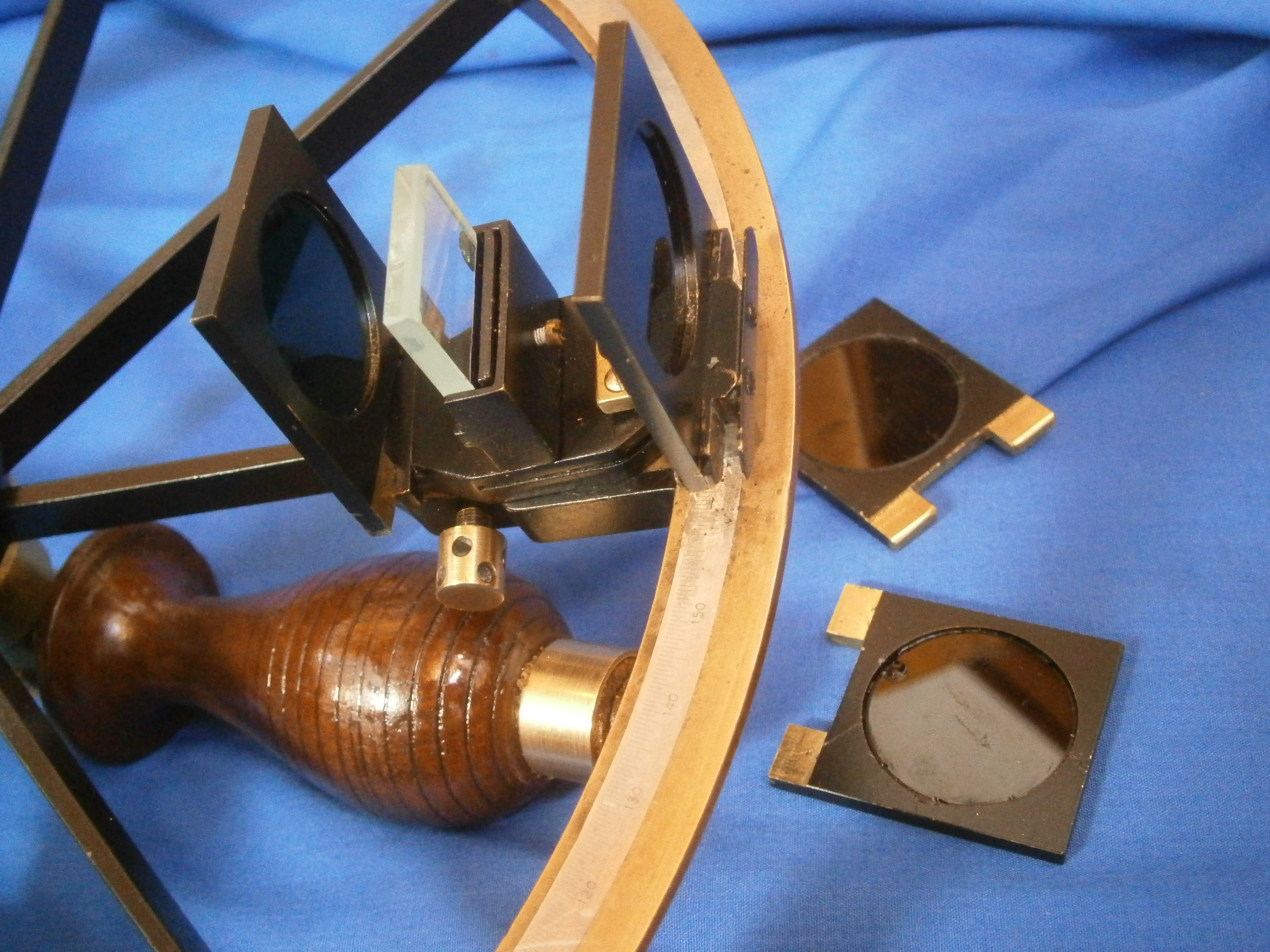
A variety of shades may be slid in place, both in the front and behind the horizon mirror, held in place by feet projecting from the base of the shades into springy clips (Figure 9). This is not a very practical way in a nautical setting as more combinations of shades would be available for the horizon than for the observed body. This tends to confirm that the instrument was intended for surveying purposes.

Leave a comment