This post is preceded by “C Plath Bubble Horizon Attachment”;“A gummed up AN5851-1 averager”, “Bubble illumination of Mk V and AN 5851 bubble sextants” , ”Refilling Mark V/AN5851 bubble chambers” , ”Overhaul of MkV/An5851 bubble chamber” , ”AN5851-1 : jammed shades carrousel” , ”A Byrd sextant restored” , ”Update on Byrd Aircraft Sextant”, “A nautical sextant bubble horizon” and “Sealing A10 vapour pressure bubble chambers.”
In 1939, the SOLD-Libellen-oktant (SOLD level-octant), made by C Plath, went into service with the Luftwaffe (German Air Force). I have not been able to discover where the “SOLD” came from, but it is a fair bet that it is an acronym which includes the words “Sextant” and “Libelle” (Level). While it was used extensively by Luftwaffe reconnaissance aircraft especially, it is less well known that Naval versions appeared, with better protection from salt water spray and a self-contained power source in the form of a rechargeable NIFE battery. The aircraft versions were powered via a flying lead. While the results of observations made with a bubble sextant at sea can be expected to be rather inaccurate, in some circumstances, on war patrol at night for example, or in poor weather when no horizon is visible, even a poor result can be better than none at all. Since this is a blog about the nautical sextant, it is with the nautical version that this post is concerned, specifically a KM2 (Kriegsmarine 2) of 1944. It differs otherwise only in minor details from the Luftwaffe version.
Please note that all illustrations may be enlarged by simply left- clicking on them. Return to the text by clicking on the back arrow.
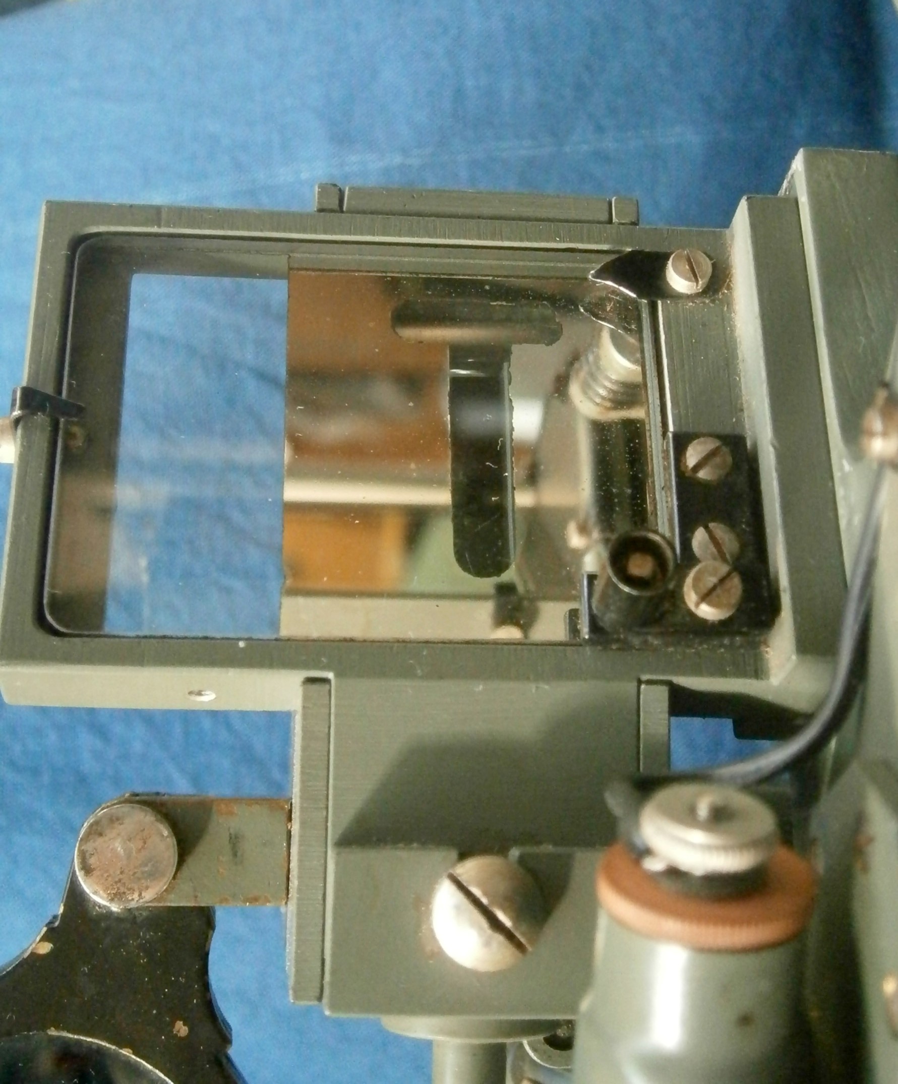
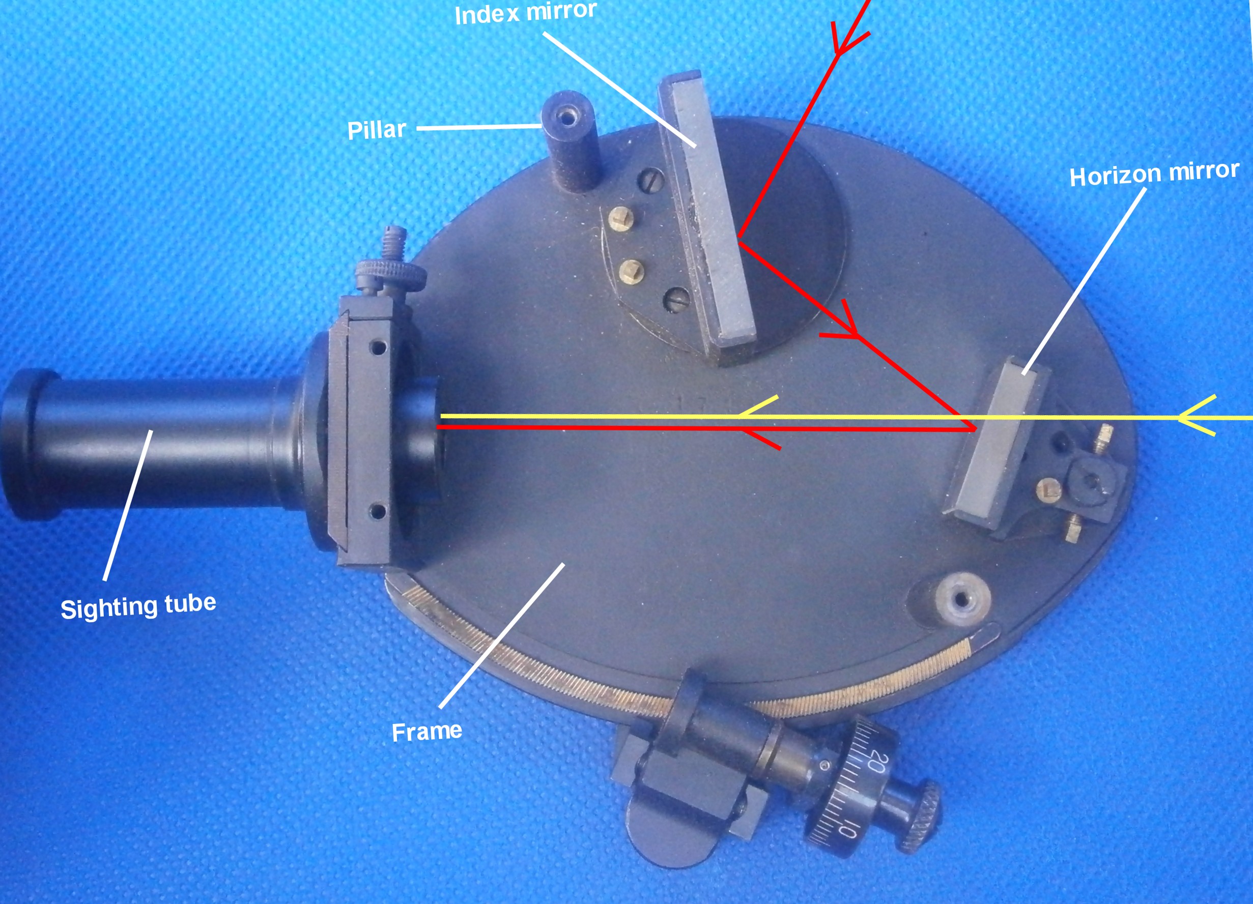
Optical lay-out
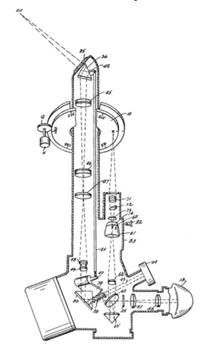
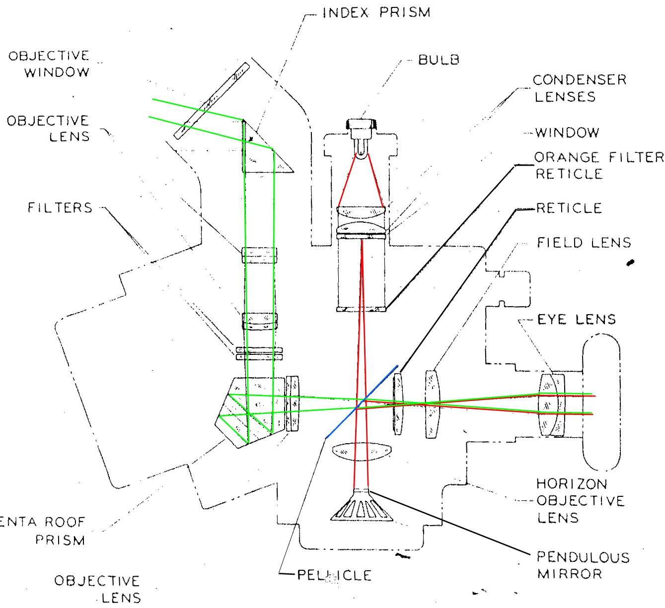
Figure 1 shows the light path. It is perhaps slightly easier to understand the path for night time observations of a star. The star is located by looking upwards through the partially reflecting mirror 5. Light from the bulb 1 is reflected off mirrors 7 and 6, through a circular bubble level 2, off the reflective face of a pentaprism 3 into an objective lens 4, whose focal plane is at the bubble. The lens renders the rays parallel, so that the bubble then appears to be at infinity as it is observed reflected off the mirror 5. While keeping the star in view, the mirror 5 is rotated to bring the image of the star and the image of the bubble together, when the angular altitude of the star above the horizontal may be read off a scale attached (indirectly) to the mirror 5. The radius of curvature of the bubble cell and the focal length of the objective lens are chosen to be the same, so that once the star and bubble images are coincident, they tend to move together when the sextant body is disturbed. For daytime observations of the sun, it is the bubble that is viewed through the mirror while the sun’s reflection off mirror 5 is observed indirectly. For this type of indirect observation, the mirror 7 is removed and a frosted window substituted, so that diffused daylight illuminates the bubble chamber, though daylight viewing with the bubble chamber illuminated by the lamp is possible too.
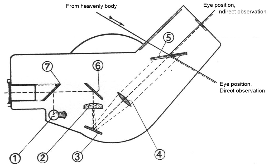
Figure 1: Light path.
Averaging observations
Pitching and rolling of a ship imparts accelerations to the bubble chamber which for practical purposes may be considered as being random, and the bubble is seldom at rest. With early bubble sextants, a handful of observations were taken of the body and the altitudes and times averaged. However, random errors are reduced as the square root of the number of observations, so that, for example, to reduce the average error to a quarter, 16 observations have to be made and to reduce them to a fifth, 25 have to be made.
The next step was to provide some sort of drum on which marks could be made by the observer when he considered the bubble and body to be in coincidence, but it was soon pointed out that the bubble might well be considered to be at rest when it was in fact the subject of a large, but constant acceleration. The next step was to cause the marker to operate automatically at intervals of about a second, leaving the observer to maintain coincidence and to choose the median at the end of the observation period. A variety of clockwork averagers giving a reading of the mean of the regular observations followed. The SOLD sextant, however, continuously integrates rather than averages the observations. There is, however, probably very little practical difference in the results obtained by a British Mark IXA instrument, which averages 60 observations over 120 seconds and the SOLD which continuously integrates observation over a period of 40 to 200 seconds. The former is, however, more compact and of a better ergonomic design.
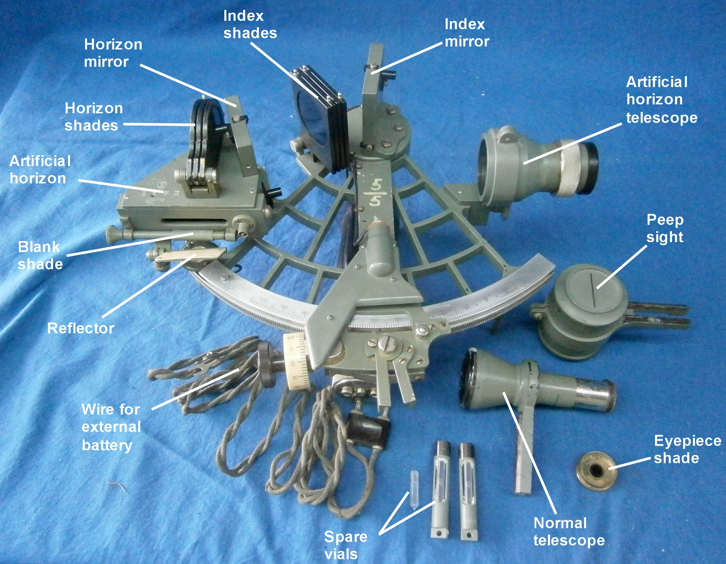
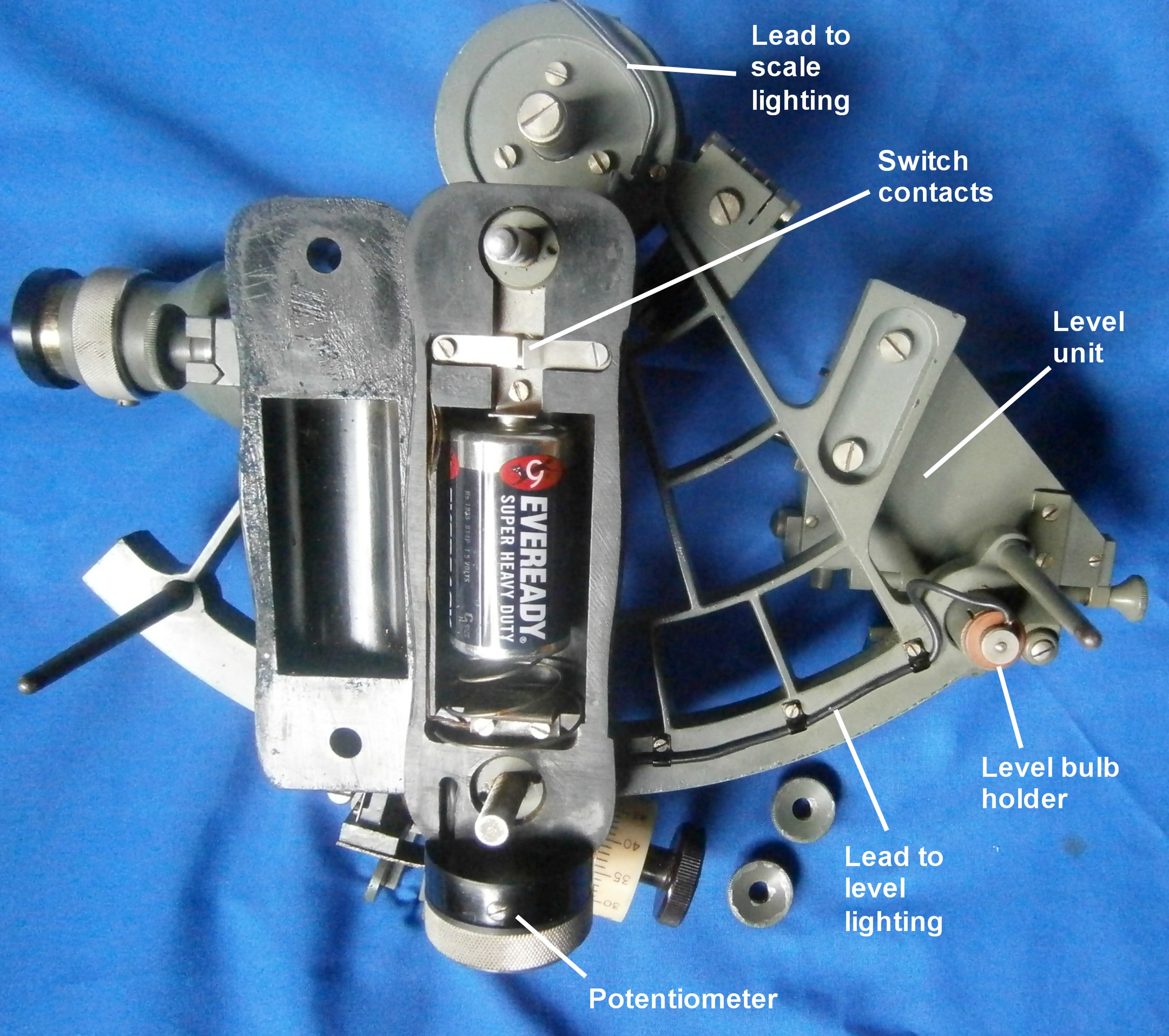
General arrangement
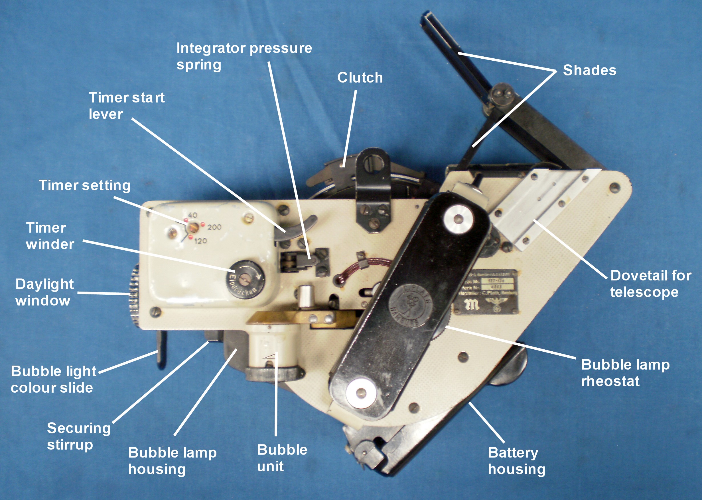
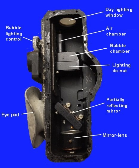
Figure 2: General arrangement, left side.
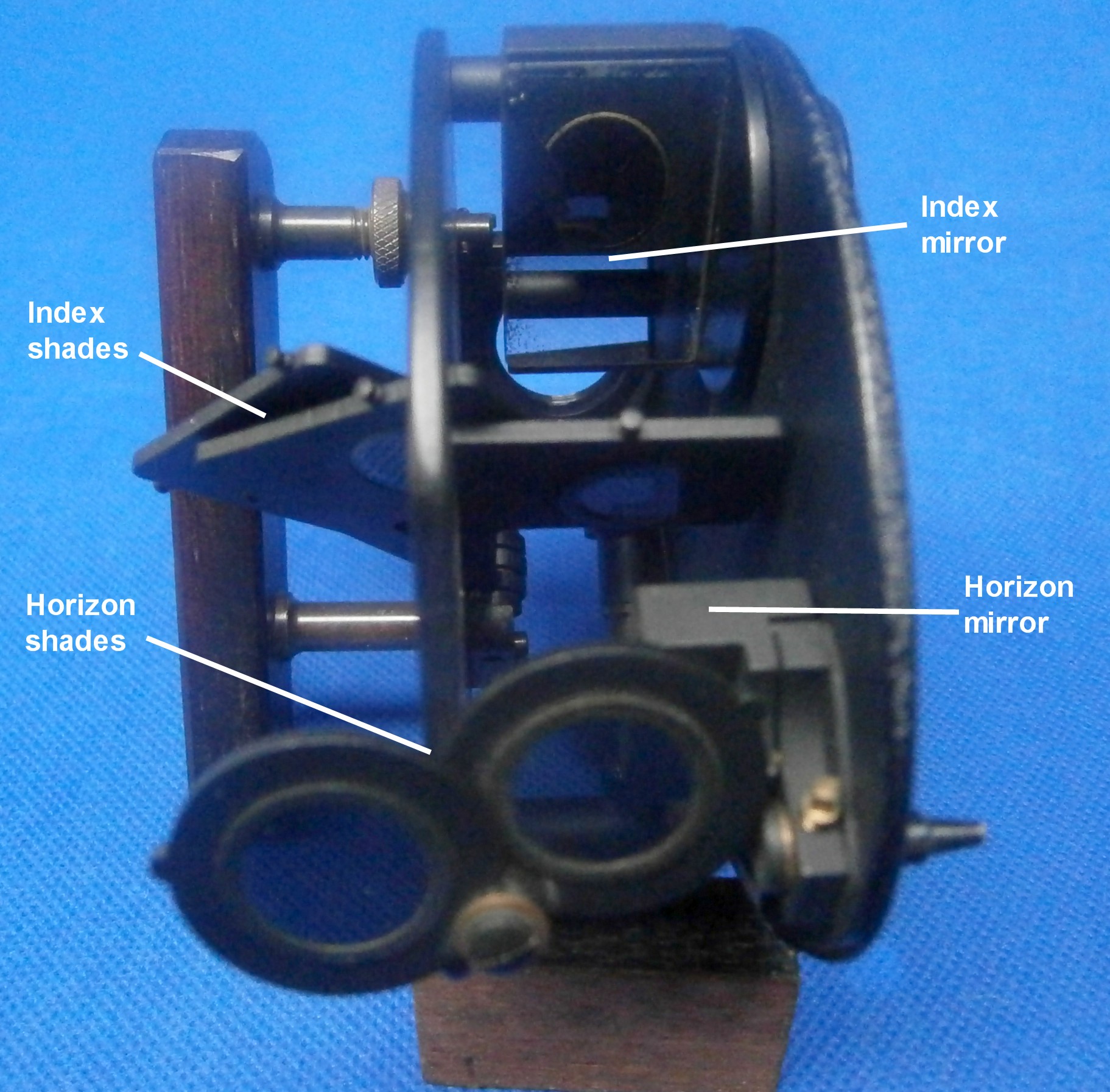
The optical parts, the battery and the integrator are sandwiched between two aluminium alloy plates joined together by pillars at intervals. Figure 2 shows the parts related to the outside of the left hand plate. At the front is a rectangular timing unit with its winding knob and starting lever. A shaft with a pinion on its end passes through the left hand plate to the integrator unit. A little below it and to the front is the daylight window which slides into a socket between the plates. This window can be withdrawn and a 45 degree mirror 7, Fig.1, substituted for night-time illumination of the bubble chamber. A slide allows a red filter to be placed in front of the bulb so that the bubble field appears to be red and night vision is preserved. The level unit control and air chamber lie outside the plat,e while the bubble chamber itself is held rigidly in the optical path between the plates. Provision is made to remove the level unit without having to dismantle the whole instrument. The left hand handle, behind the bubble control, has within it a rheostat to control the brightness of the bubble lighting, and below and to the rear of this can be seen part of the battery housing which lies between the plates. A slide to receive a 2-power telescope is to the rear of the top of the handle and above this, mounted between the plates, is a bracket containing two filters or shades to reduce the brightness of the sun or moon before their rays reach the observation mirror (5, Fig 1).
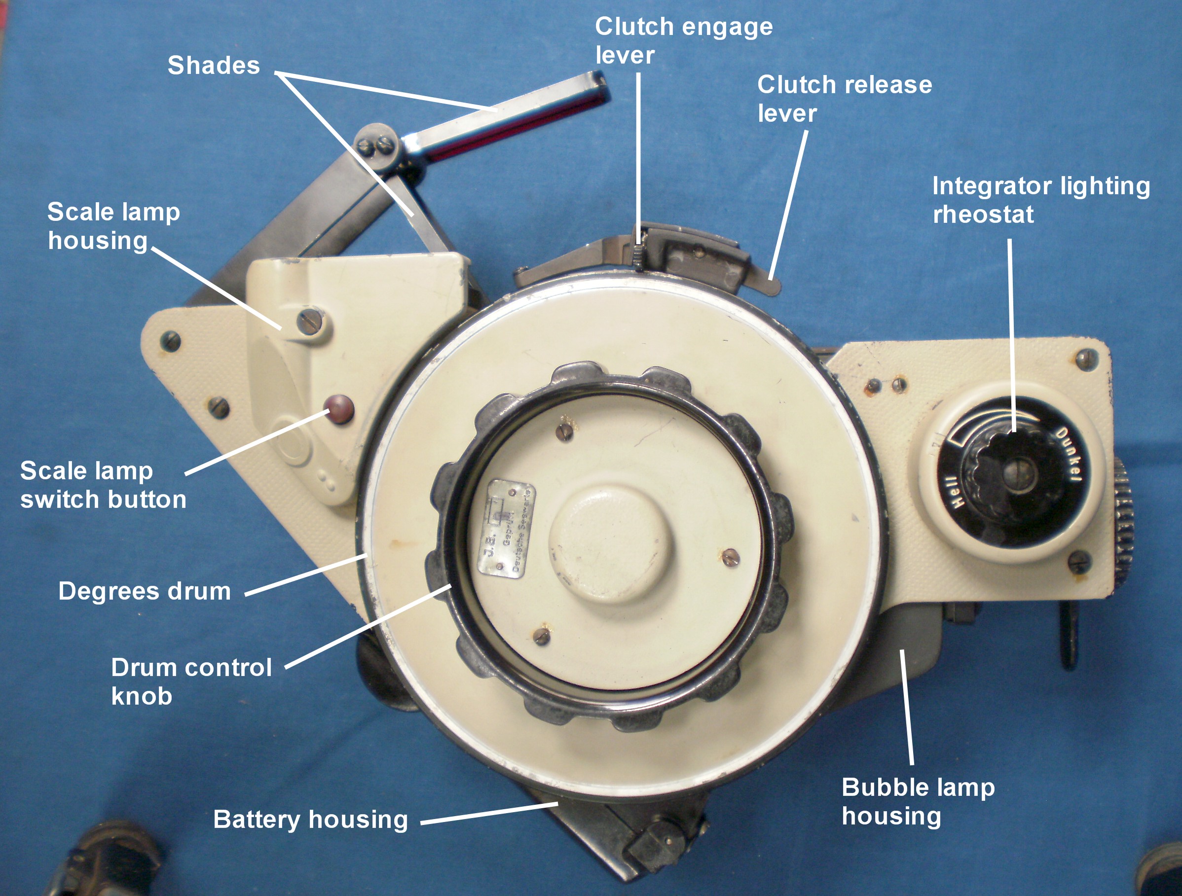
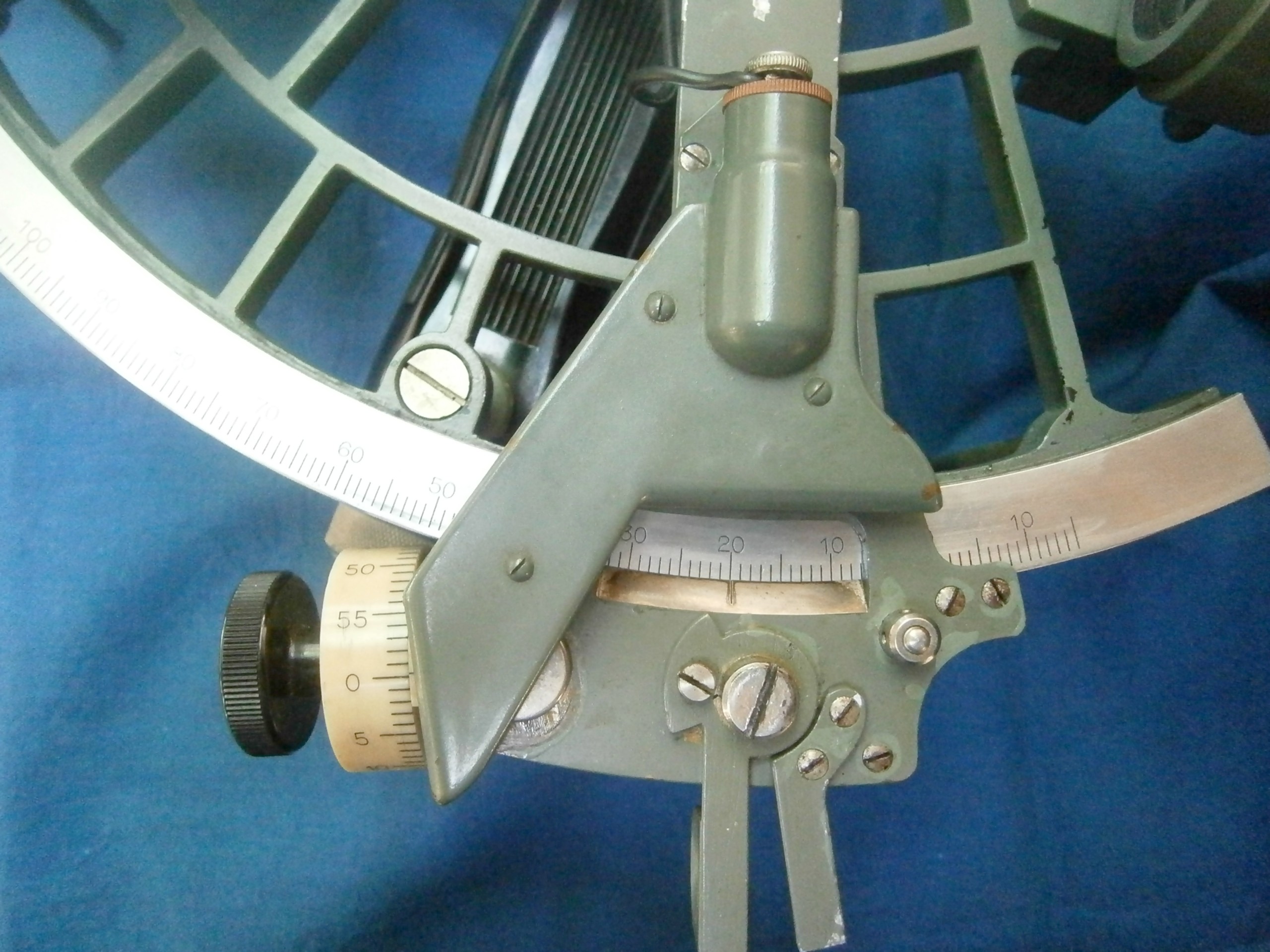
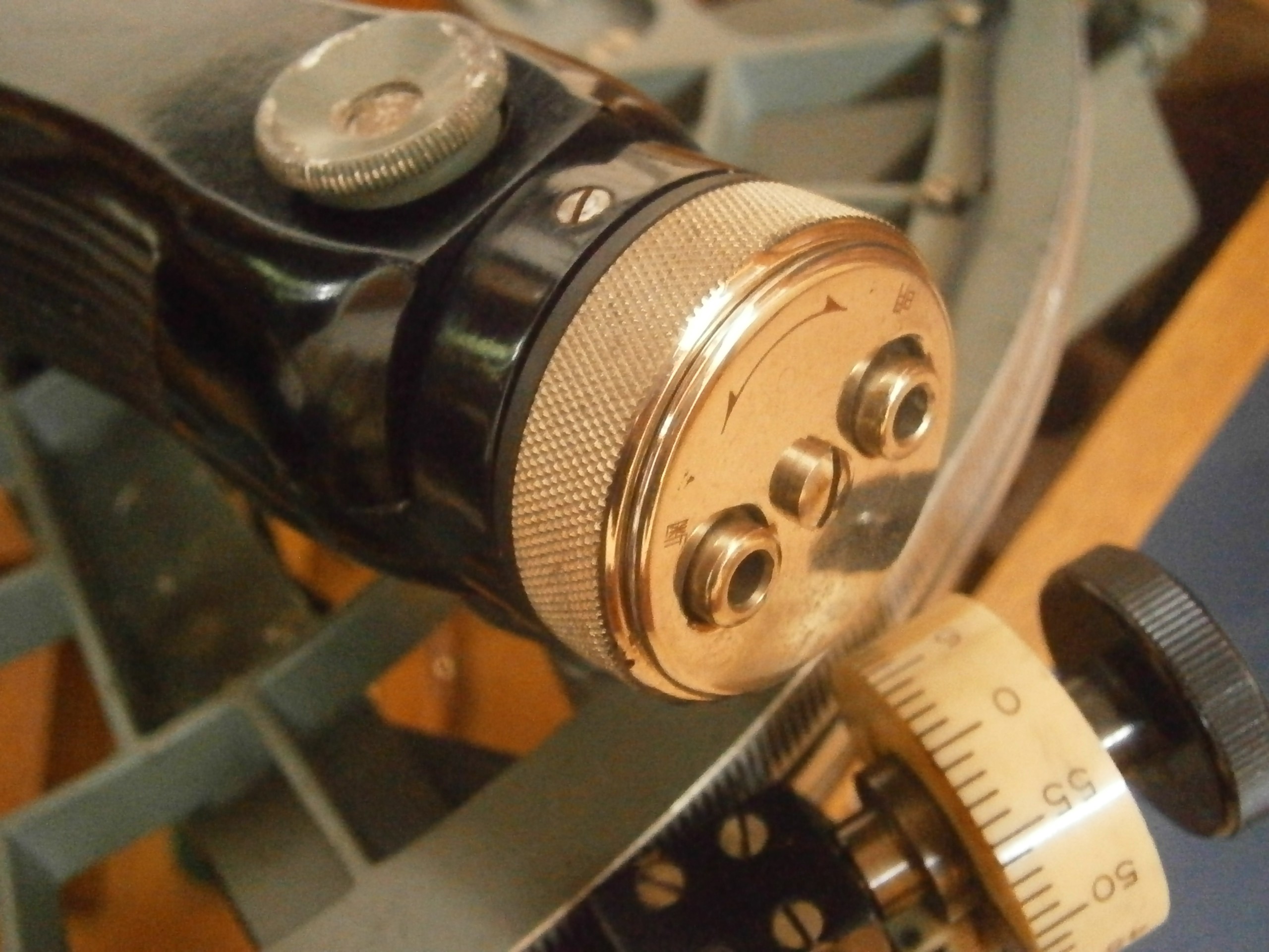
Figure 3: General arrangement, right side.
Figure 3 shows a view of the right hand side of the instrument. At the front is a rheostat used to vary the brightness of illumination of the scales. It is marked “Hell” (light) and “Dunkel” (dark). Behind this is the main drum, the periphery of which is divided into three lots of ten degrees and a vernier (not normally used) allows readings to one minute. There is a mechanism within the hum of the drum which limits it to two and two-thirds turns, so that altitudes up to 80 degrees may be measured. As the drum rotates, a linkage to the observation mirror causes it also to rotate. Once approximate coincidence between the bubble and body images has been obtained, the clutch above the drum, is engaged, linking the drum to the integrator mechanism. The values of further movements of the drum to maintain coincidence are then integrated. to give a mean value at the end of the observation period. Above and to the rear of the drum is a housing for the illuminating system of the scales. At the end of the observing period, the integrator lighting comes on and when the scale lamp switch button is depressed it goes out and the scales lighting comes on.
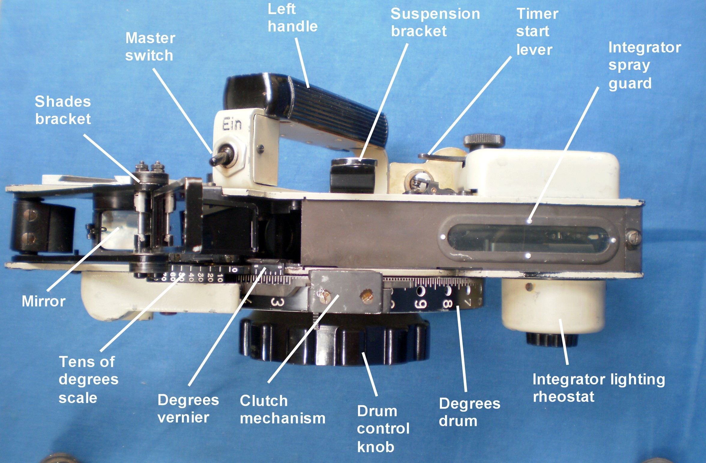
Figure 4: General arrangement top view.
Figure 4 shows some parts already described. There is an additional view of the shades bracket with the shades in the operating position. The main switch can be seen at the top of the handle with the on position (“Ein”) marked. The various scales, illustrated more clearly in Figure 5, are shown, together with the window through which the integrator reading is viewed. The observing mirror is seen for the first time. Figure 5 shows a view of the top as if from a body at an altitude of about 30 degrees.
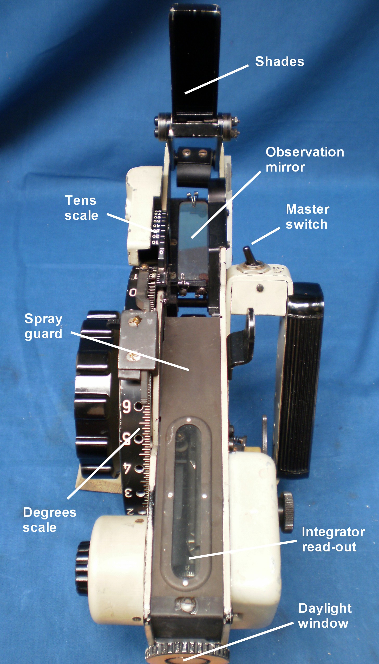
Figure 5: View as from a body at 30 degrees altitude.
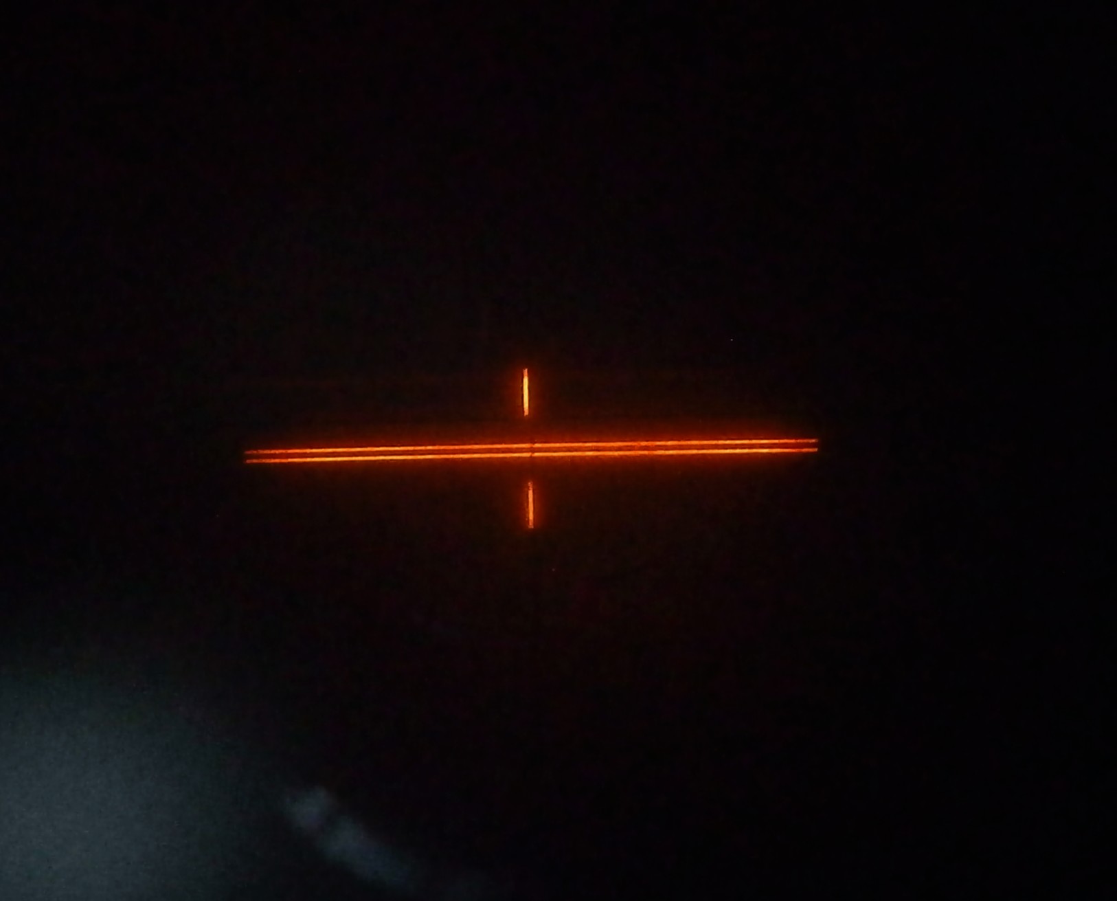
Figure 6 shows a view seen as if taking an indirect observation at about 30 degrees. The image of the bubble field can been seen in the objective lens, through the semi-reflective observation mirror.
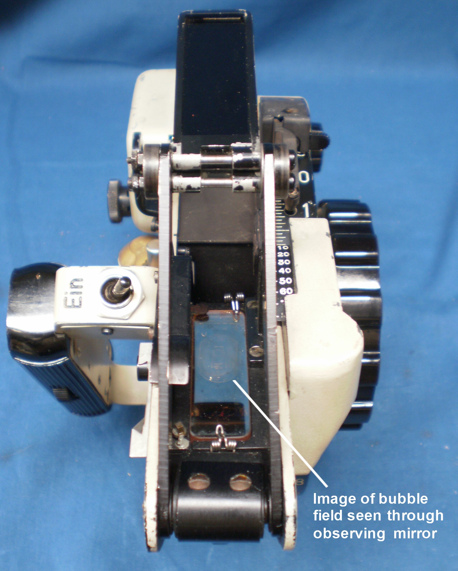
Figure 6: View of indirect observation.
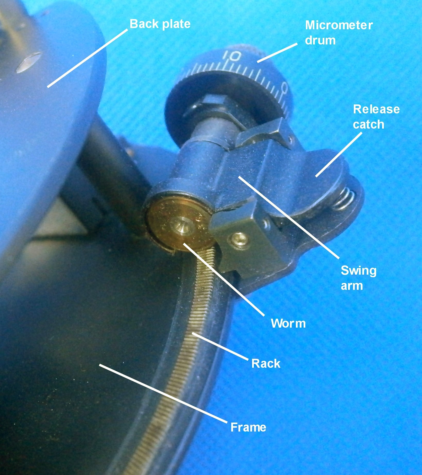
Observation mirror controlling mechanism
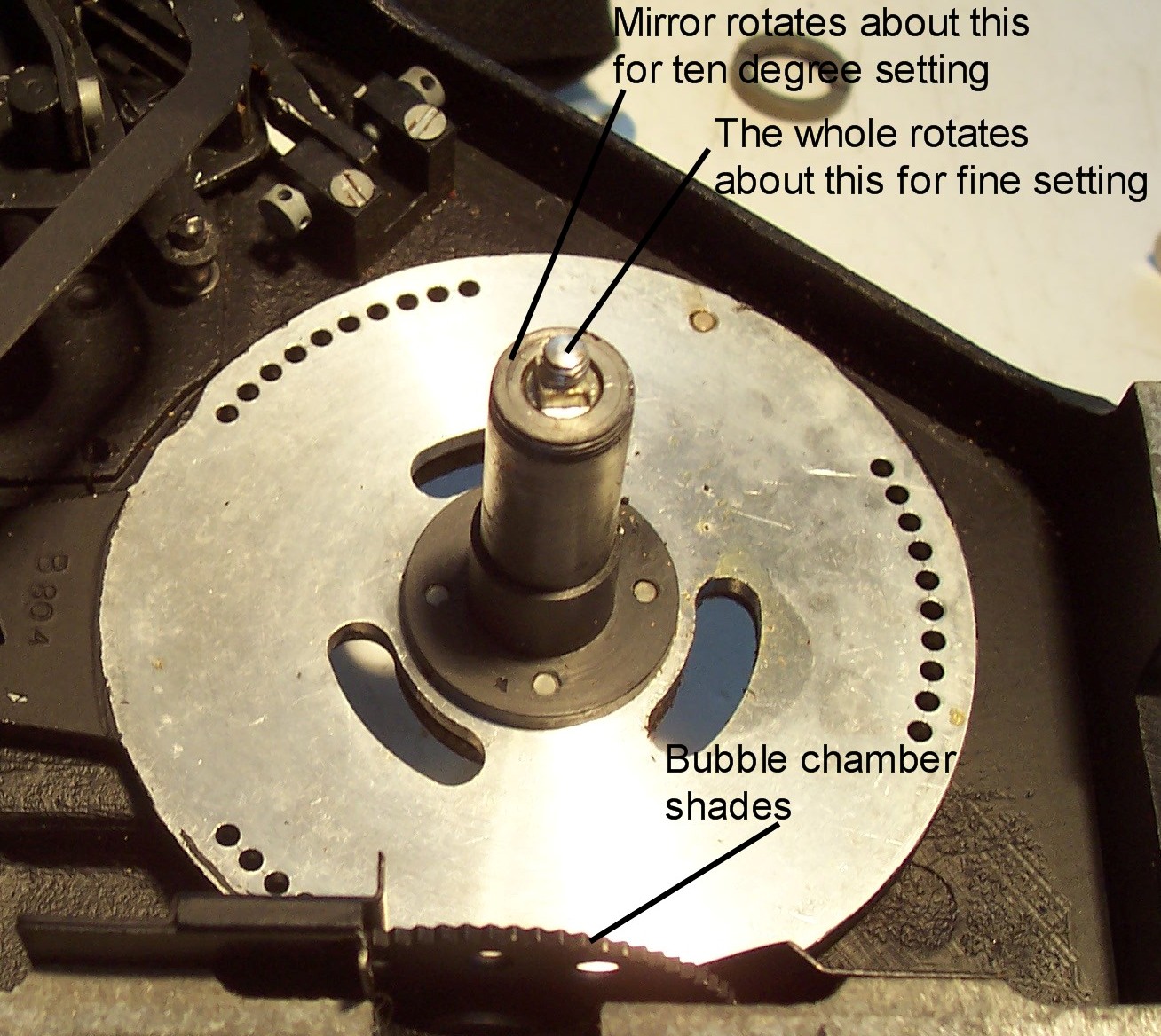
The inner surface of the drum, shown face-on in Figure 3, has a spiral groove machined into it (Figure 7).

Figure 7: Drum spiral.
The drum rotates about a fixed conical axis (Figure 8) and a follower, seen on the right-hand side of the figure, engages in the spiral groove of the drum. A lever attaches the follower to the axis of the observing mirror, so that as the drum is rotated, the follower moves out along the spiral, thus rotating the mirror about its axis. A long helical spring prevents backlash by keeping the follower against the inner wall of the spiral groove.
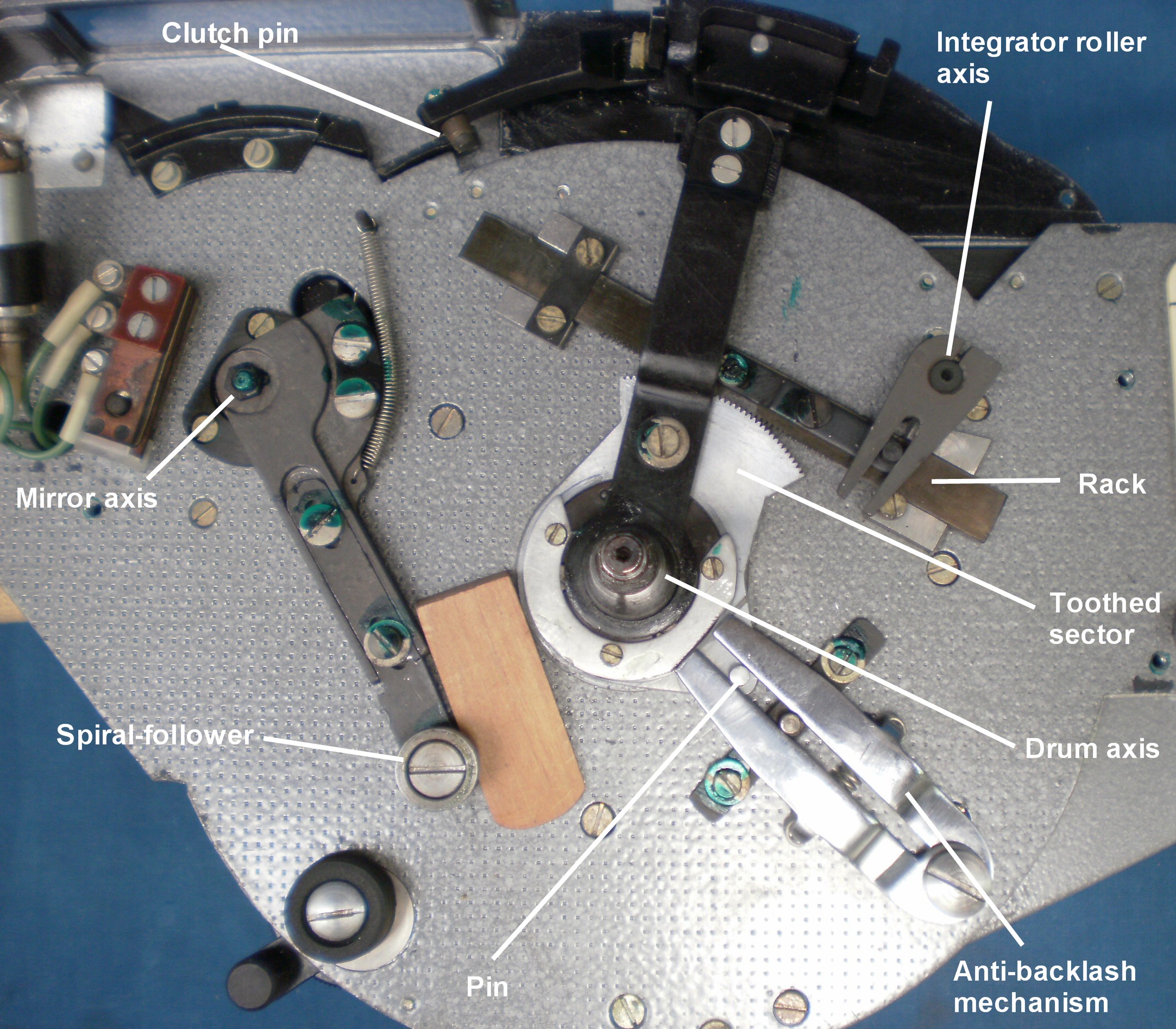
Figure 8: Controlling mechanism
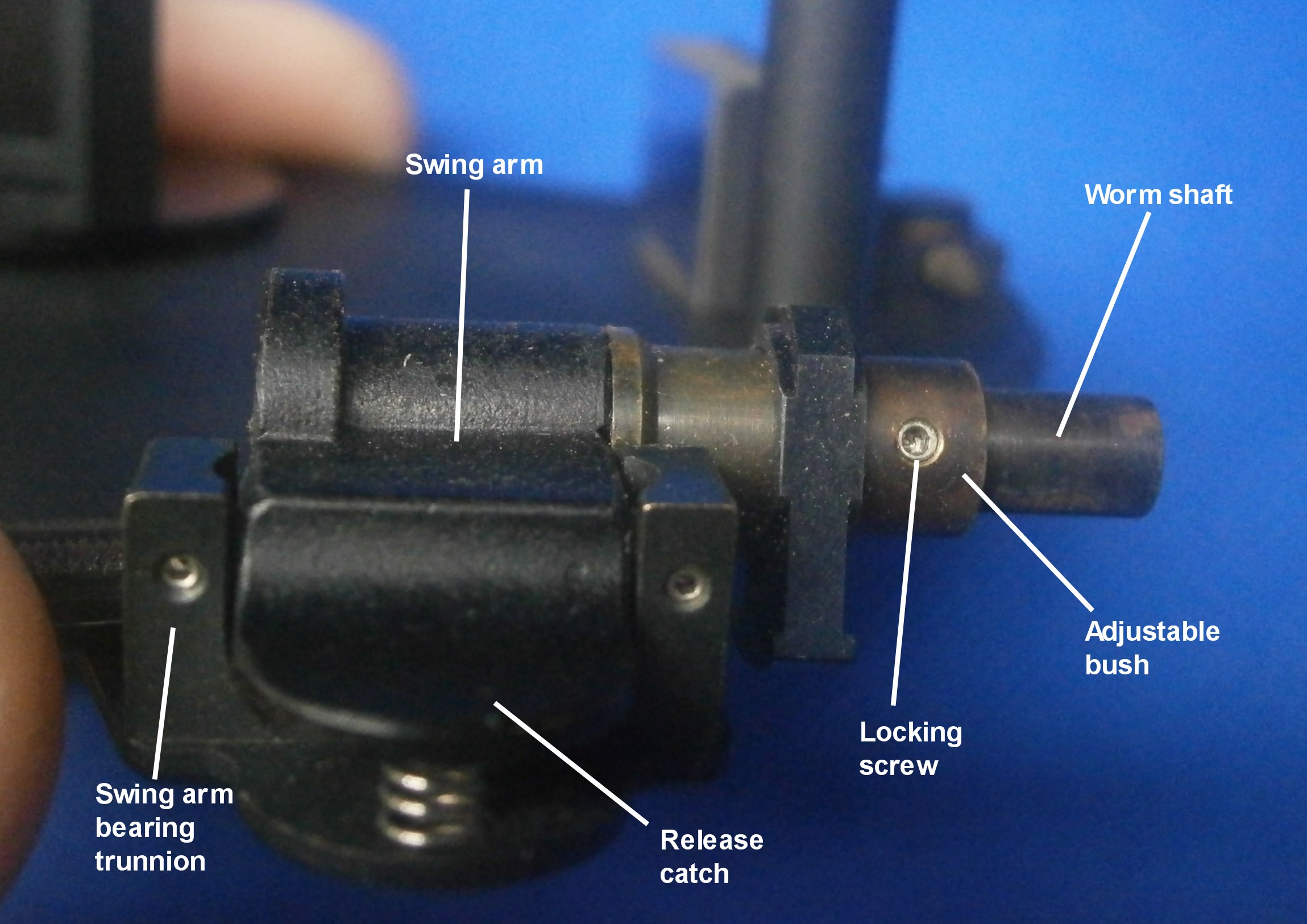
Integrator controlling mechanism
When the clutch-engage lever (Figure 3) is depressed a spring presses a conical peg into one of the holes drilled radially into the periphery of the drum at each whole number of degrees. This then links the drum to a radial lever arm that rotates about the drum axis, seen at about 1 o’clock in Figure 8. The teeth of a sector attached to the lever and rotating about the same axis engage with a rack, one end of which carries a pin which engages with a fork attached to the integrator roller axis. Thus, as the drum is rotated back and forth to maintain coincidence between the observed body and the bubble, the integrator axis is also rotated. The spring-loaded forked device seen at about 5 o’clock in Figure 8 prevents backlash in both directions via a pin at the lower right of the sector. Figure 9 shows the mechanism in operation as if the drum had been rotated forwards. Rotation backwards would engage the other jaw of the fork.
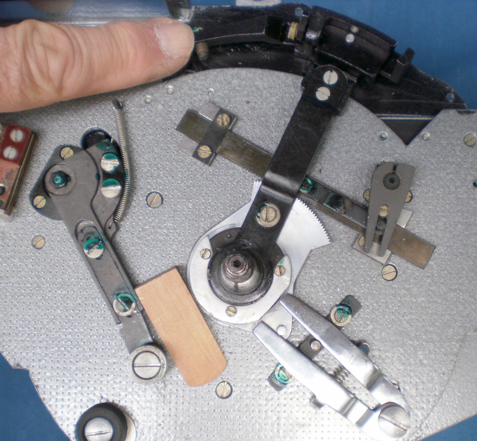
Figure 9: Anti-backlash mechanism in operation
Integrator mechanism
On the inner end of the integrator roller axis is a roller which is vertical when the radial lever arm is in the mid-way position with the clutch engaged (Figure 10). The axis runs in ball bearings while the roller itself rotates about plain conical bearings. A long horizontal spindle is pressed against the roller by a spring mechanism on the right hand plate. When the timer is started, its clockwork motor pinion engages with a rack attached to the carriage that carries the spindle and moves it from right to left. As long as the roller remains at right angles to the spindle, it simply rolls along it, but as soon as the roller is tilted, the resultant forces cause the spindle to rotate one way or the other, depending on which way the roller is tilted. The rate of spindle rotation is proportional to the amount of tilt.
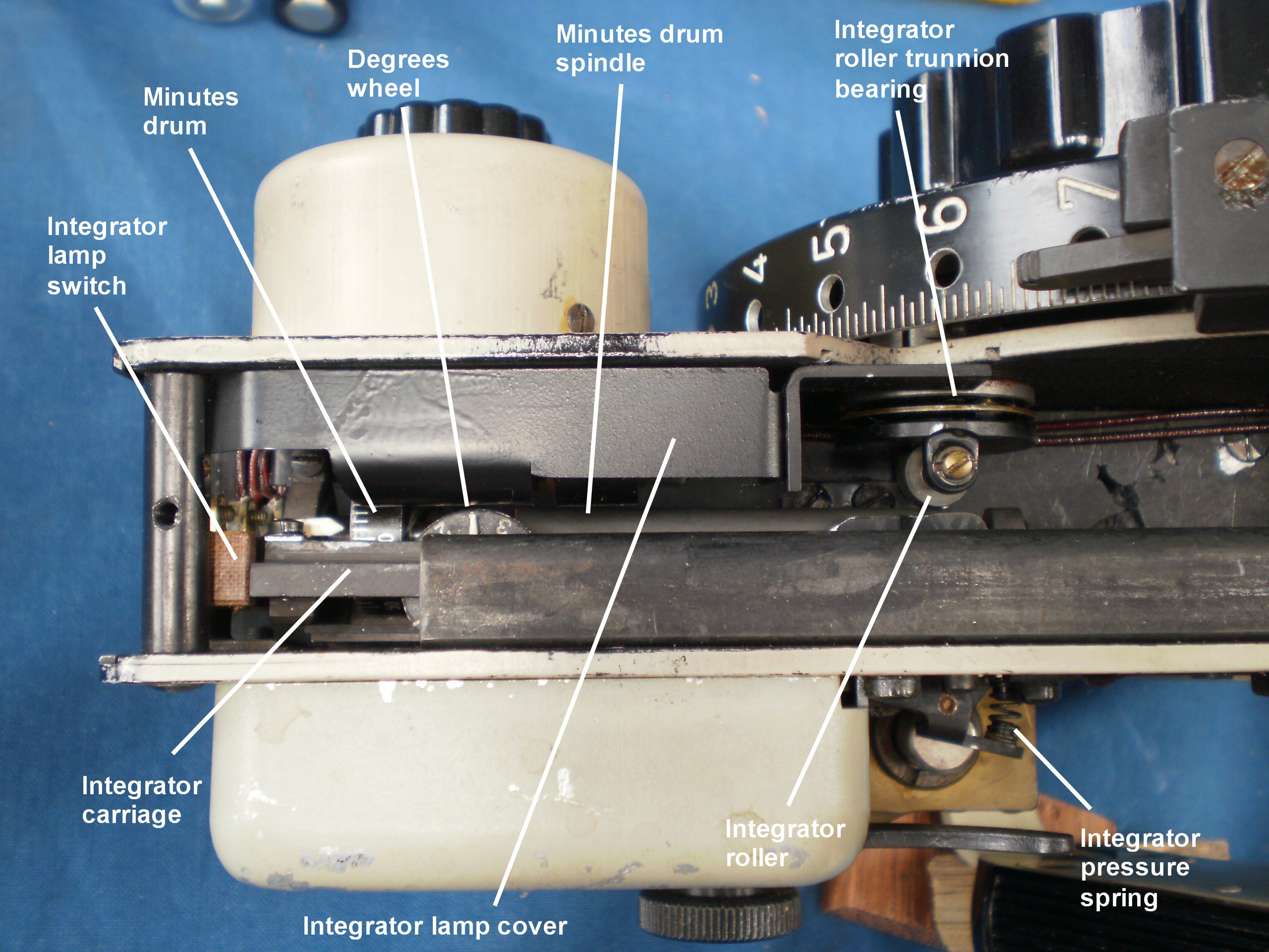
Figure 10: Integrator mechanism.
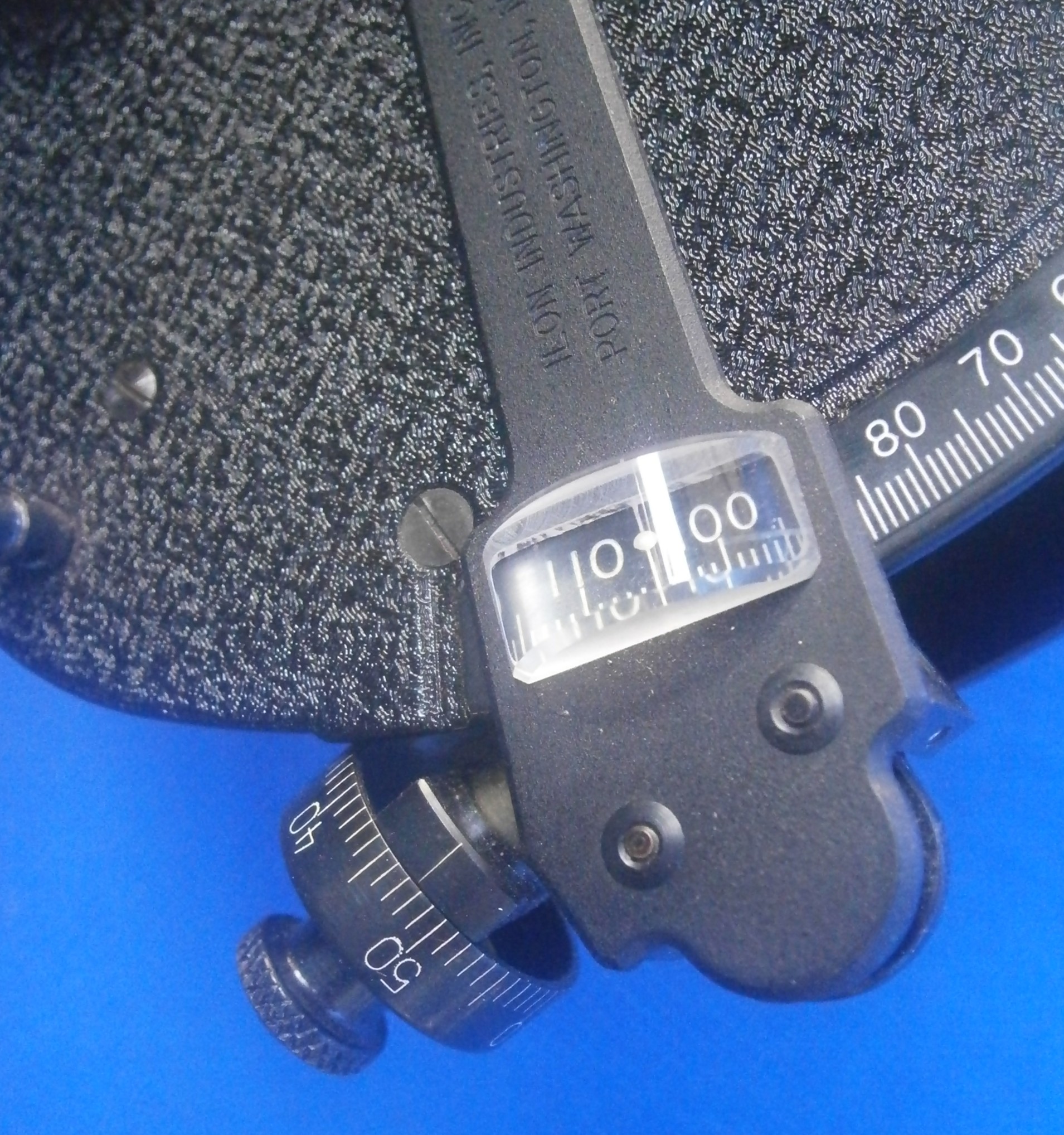
Figure 11 shows the integrator in operation with the roller tilted. At the left end of the spindle is a small drum which shows the integrated minutes of deviation of the main drum from the mid position and a disc geared to this drum indicates the total number of degrees of deviation, offset by three degrees in order to avoid subtraction when arriving at the final result. After the observation, the reading of the tens of degrees scale, the whole number of degrees shown on the main drum and the degrees shown on the integrator disc are added to the minutes on the integrator drum. The time is of course taken from the mid point of the observation. The integrator read-out is shown in close up in Figure 17, below.
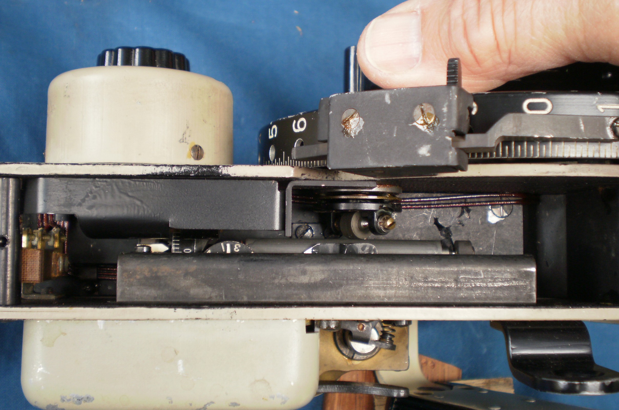
Figure 11: Integrator in operation.
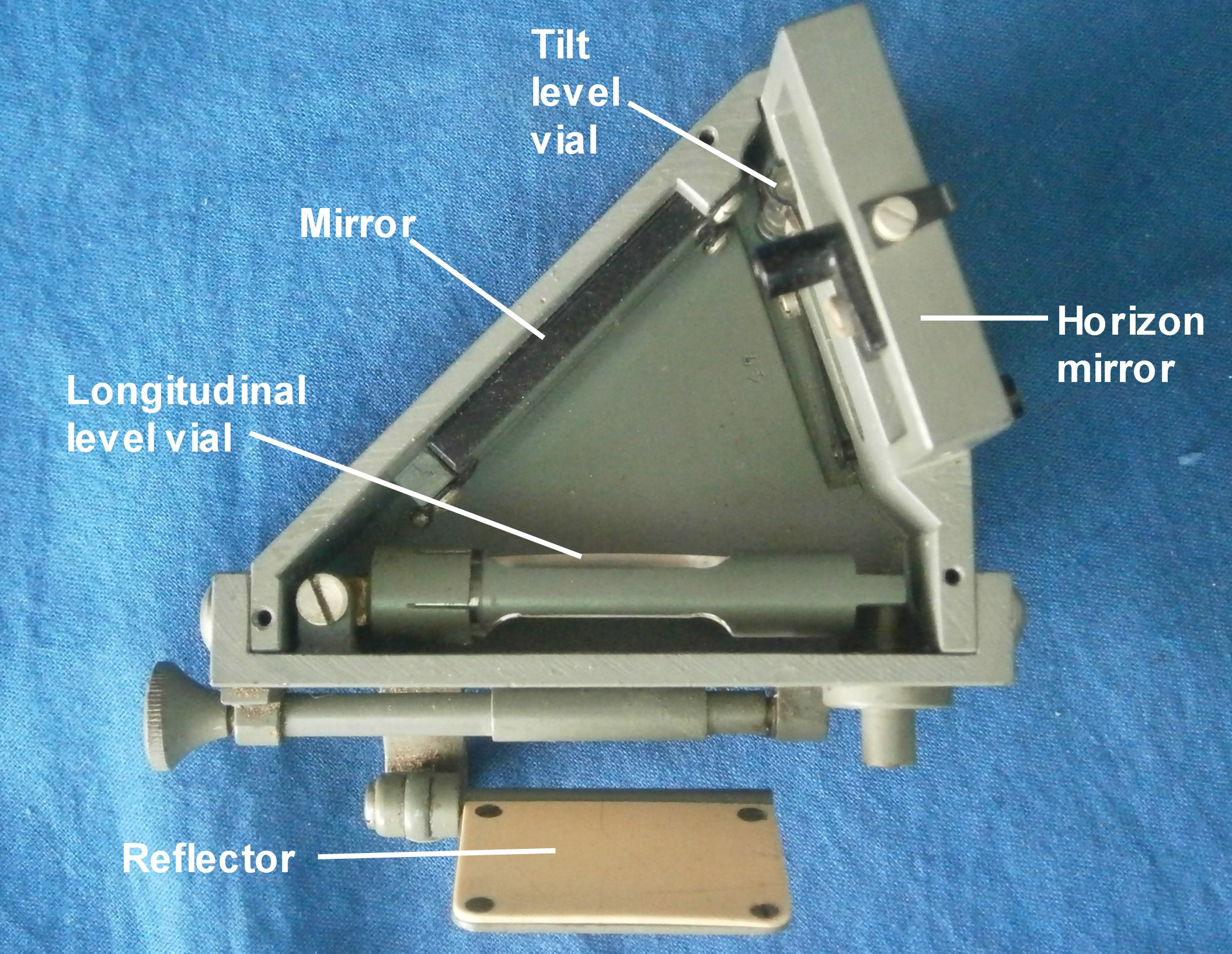
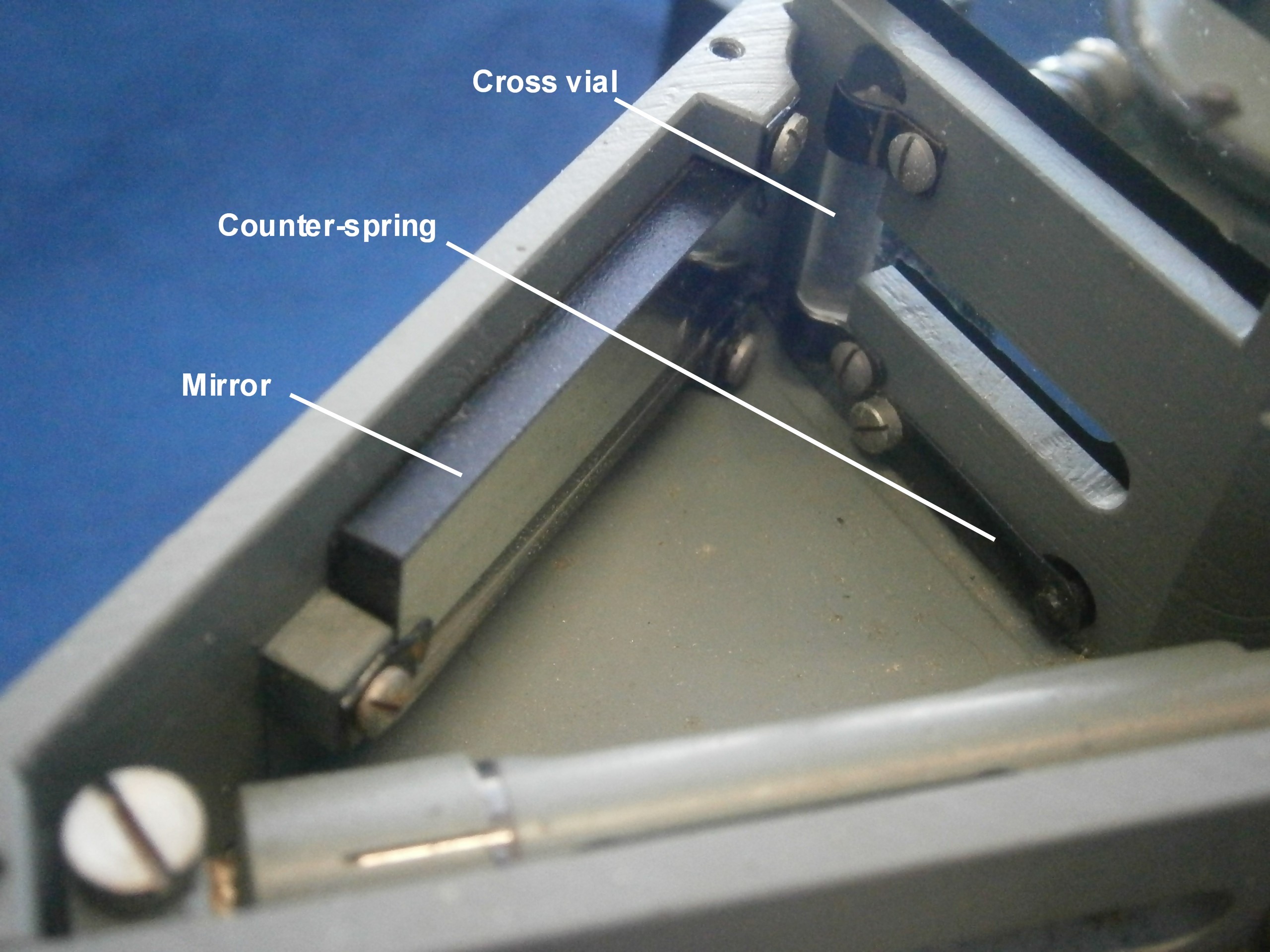
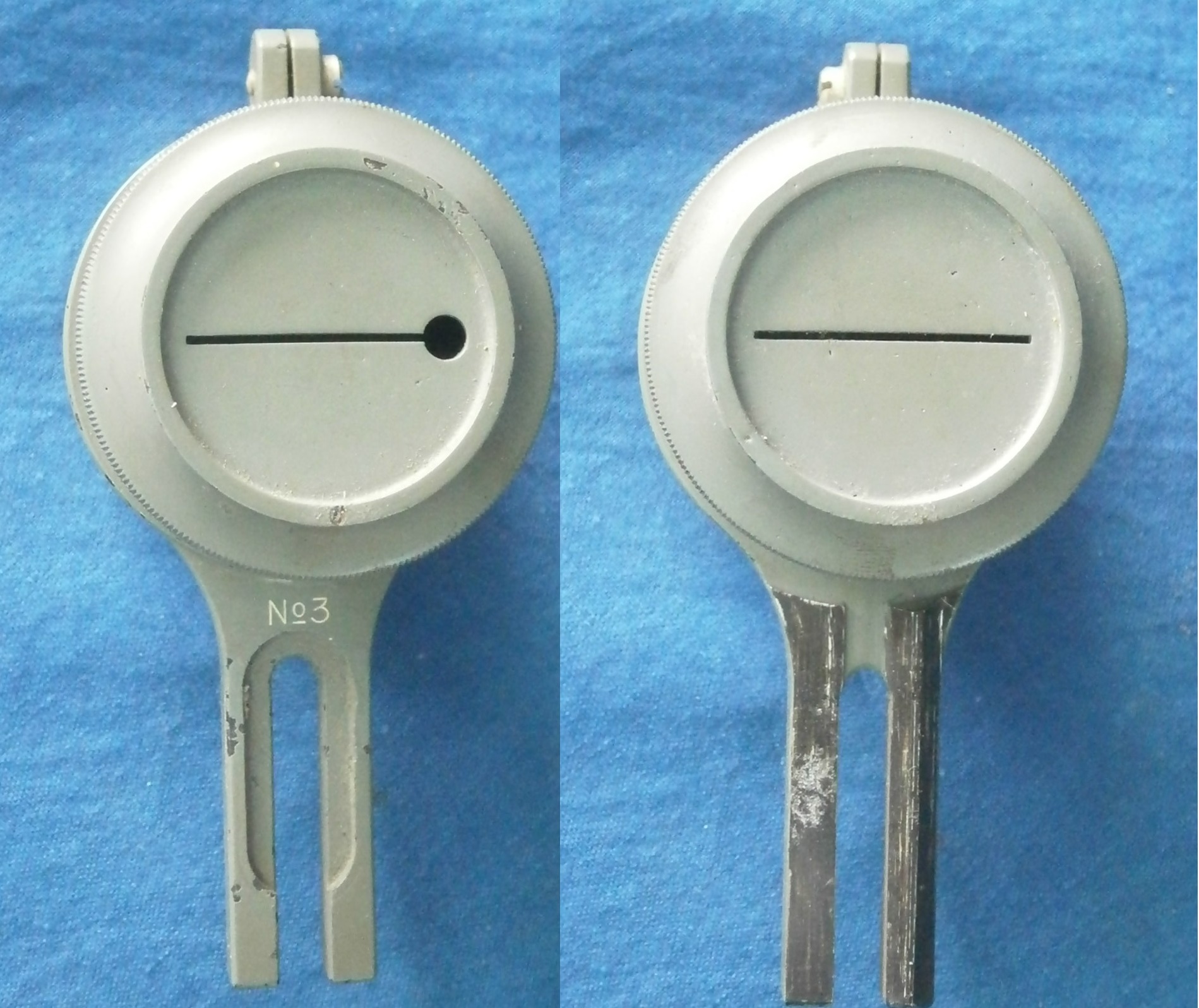
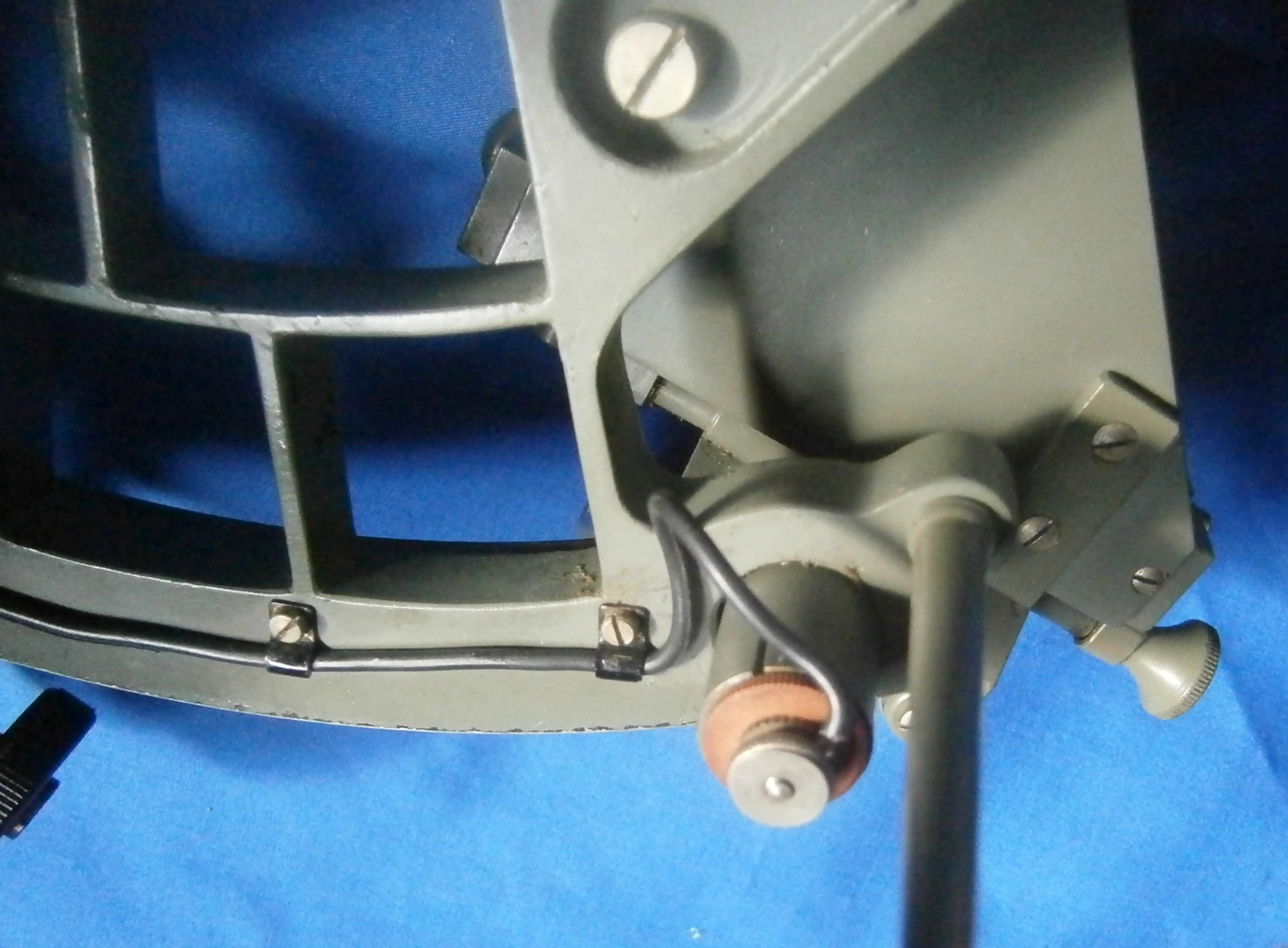
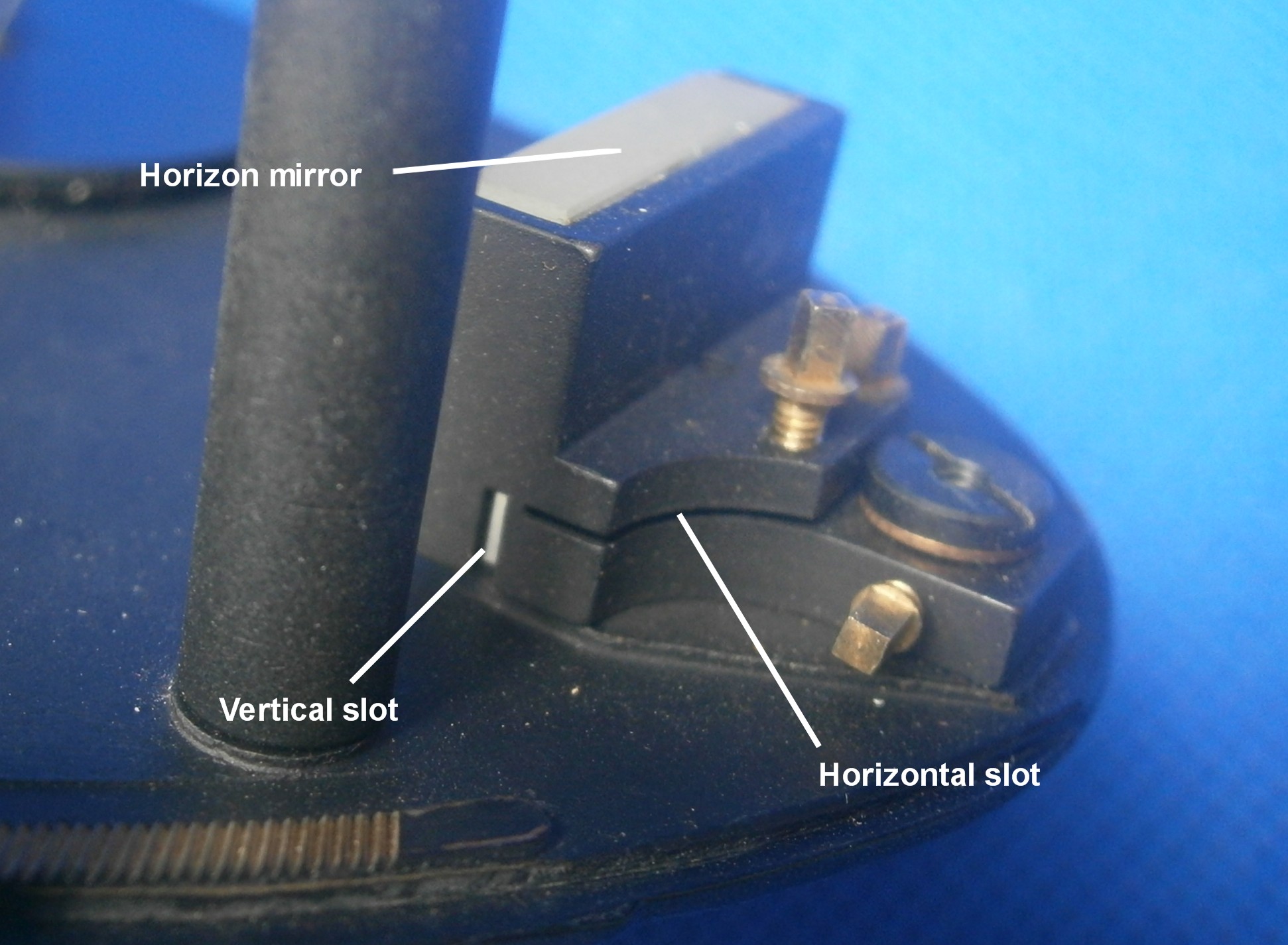
The level unit
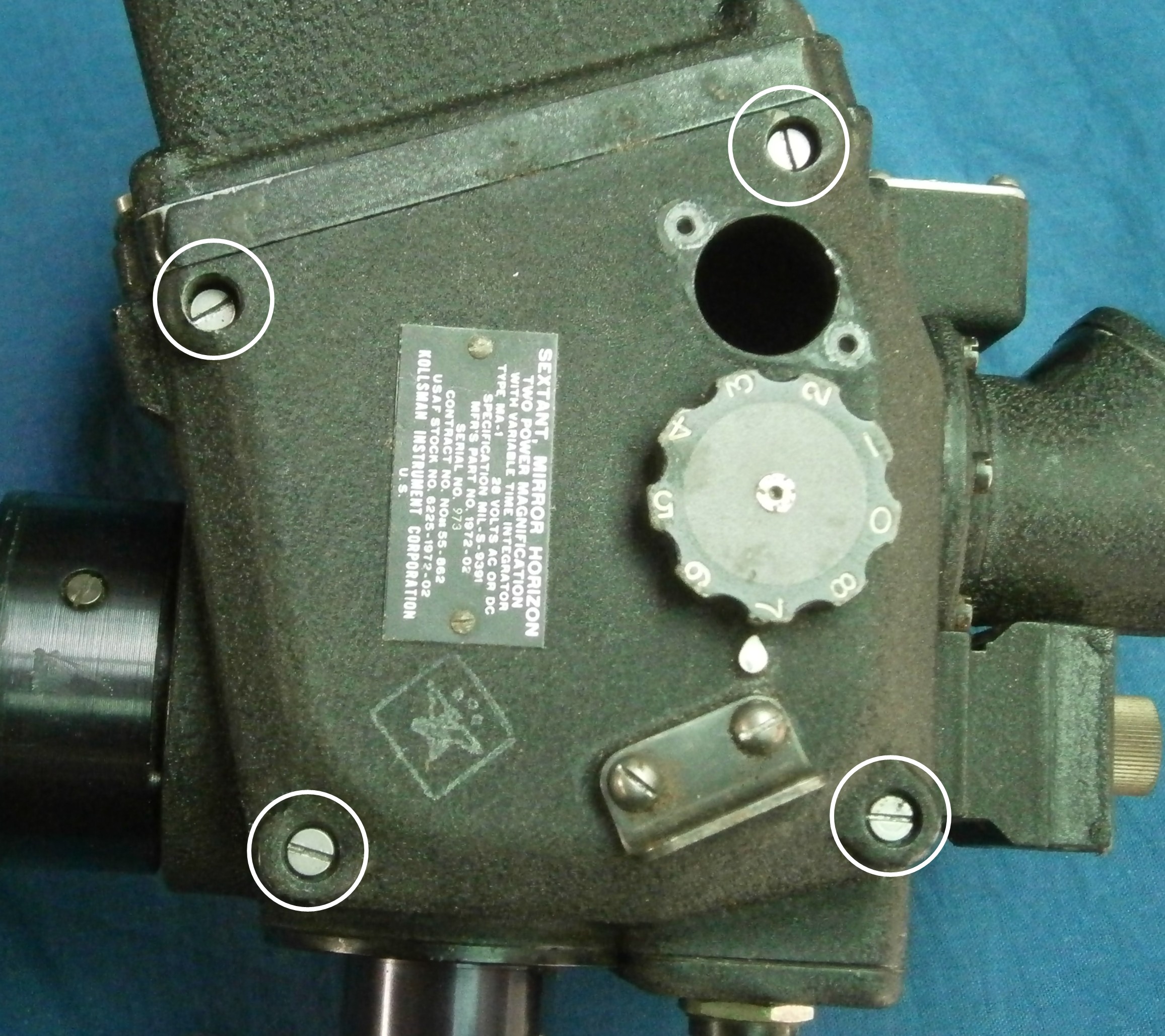
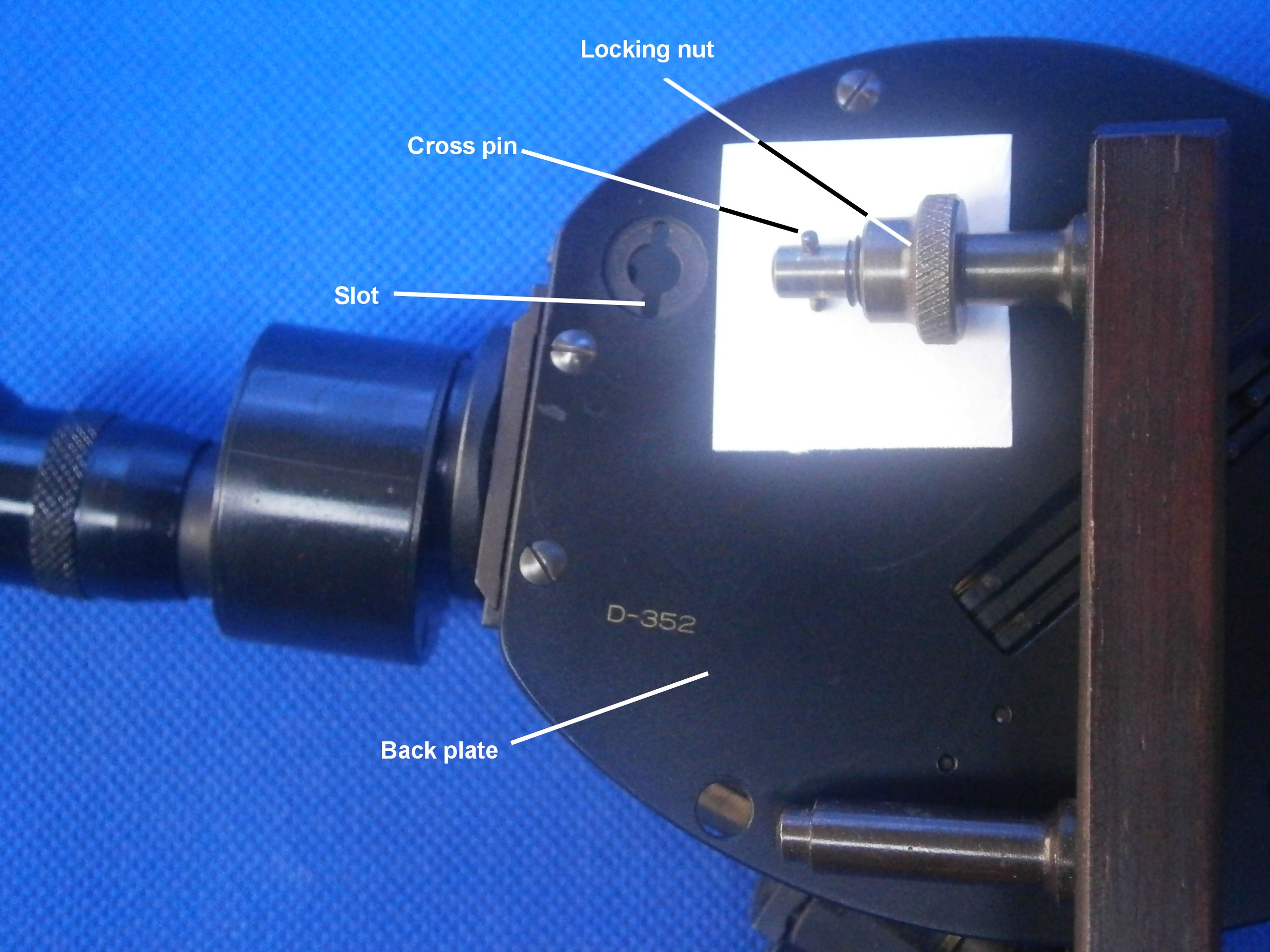
I have given details of the construction and principles of the level unit in the preceding post (26 June 2012) so will not repeat them here, but will describe how to remove the unit from the SOLD. Figure 12 shows the location of the locking screw that secures the unit in the instrument. It is captive in a wedge that pushes down a short arm that in turn forces the level unit against a machined seat between the plates. Unscrewing it withdraws the wedge.

Figure 12: Level unit removal ,1.
Figure 13 shows the wedge fully withdrawn, when the slotted head pin just below where the wires enter the plate is pushed upwards to release the arm from the level unit.
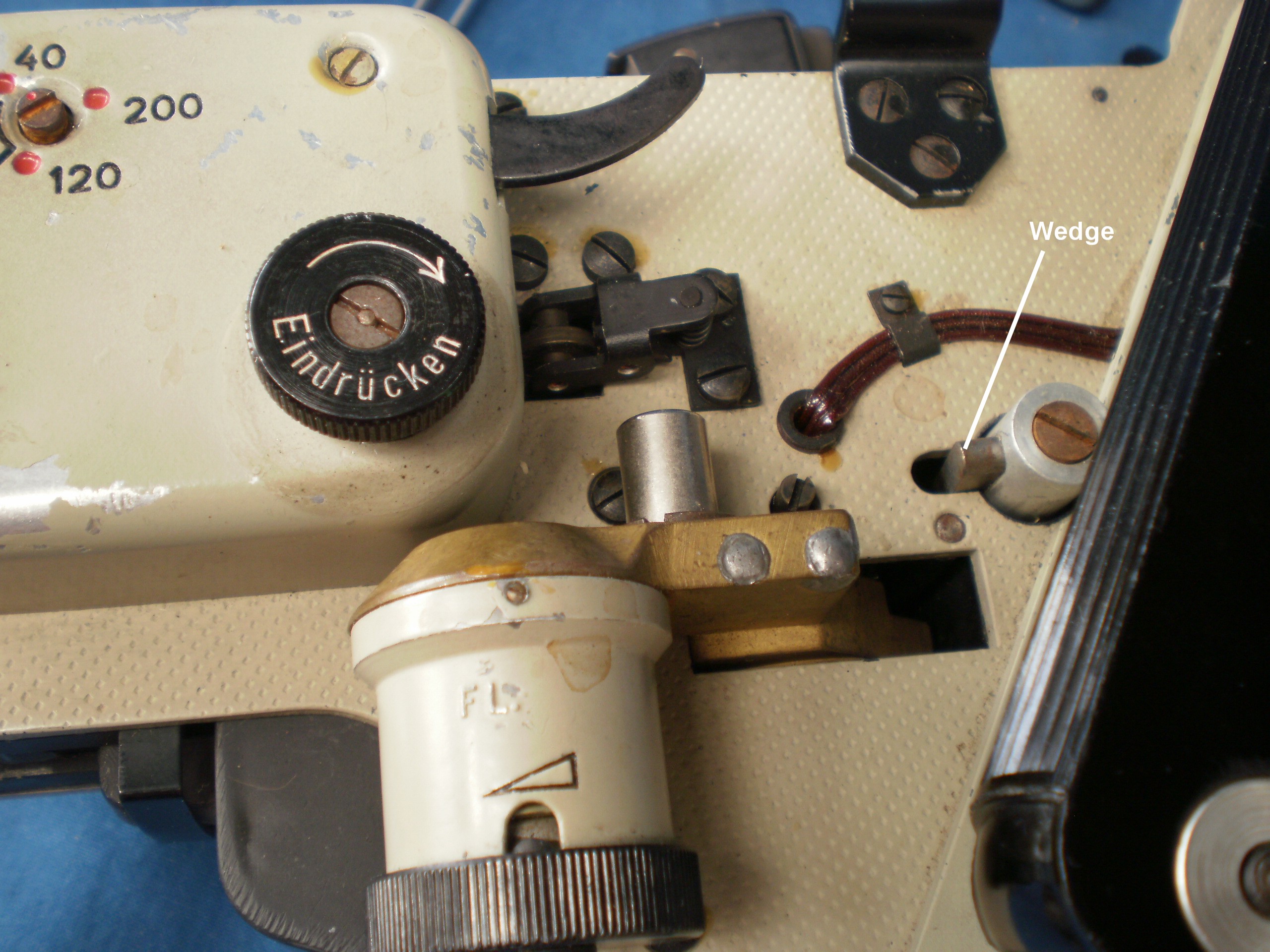
Figure 13: Level unit removal, 2.
Figure 14 shows that two conical pins on the lever arm locate the level unit accurately in position.
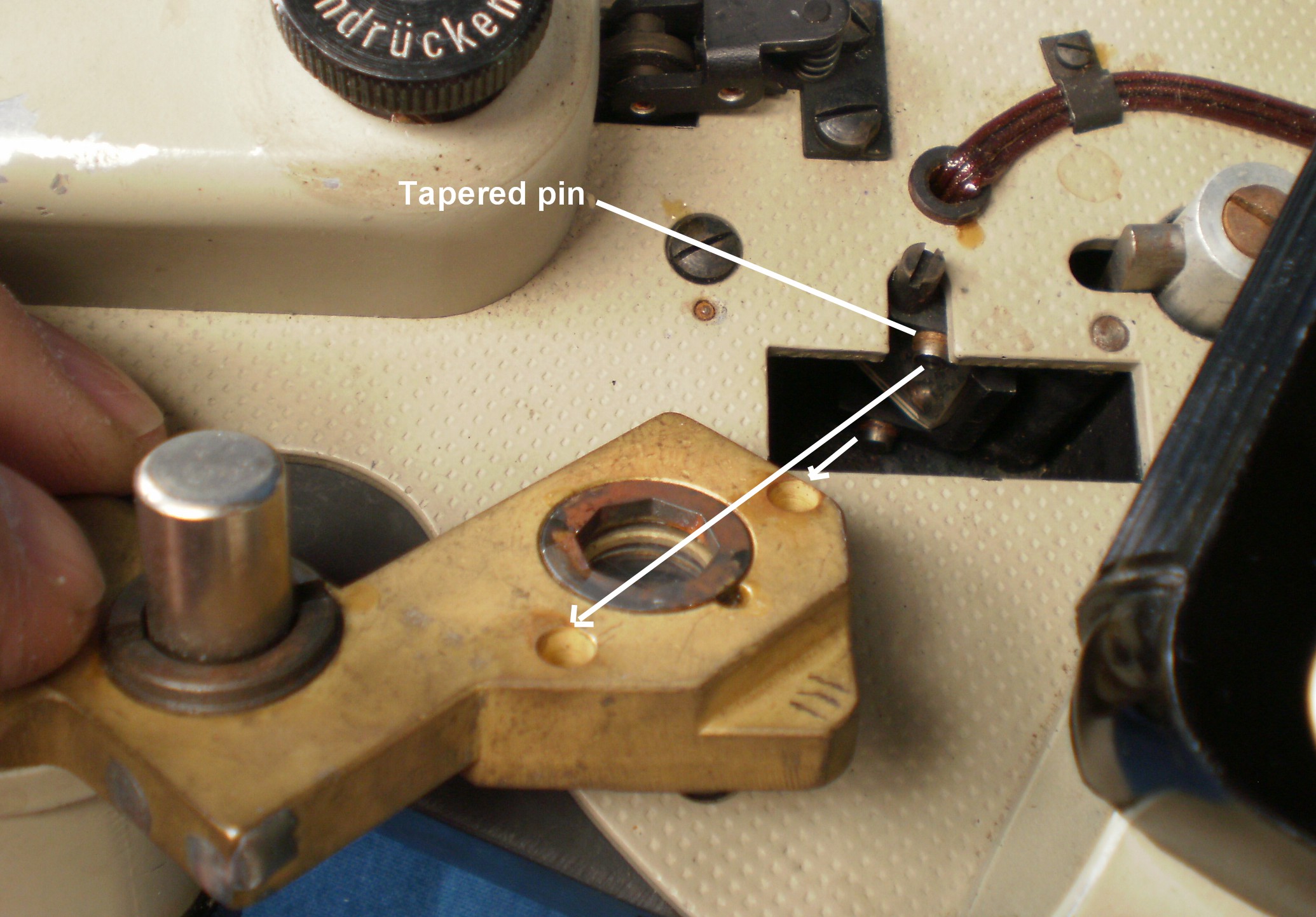
Figure 14: Level unit removal completed.
Lighting system
A master switch is placed at the top of the left hand handle.
a) Level unit.
When the securing stirrup between the plates under the front of the instrument is swung forwards, the cover to the bubble lamp can be swung backwards to reveal the lamp in its socket and a slide (Figure 14). The slide has a plain and a red filter, so that if required, the bubble illumination can be made in red light, to preserve night vision. The bulb is 2.4 volts with a 5 mm bayonet fitting and the ground-glass exterior is rather delicate. The rheostat in the left handle controls the lighting intensity.
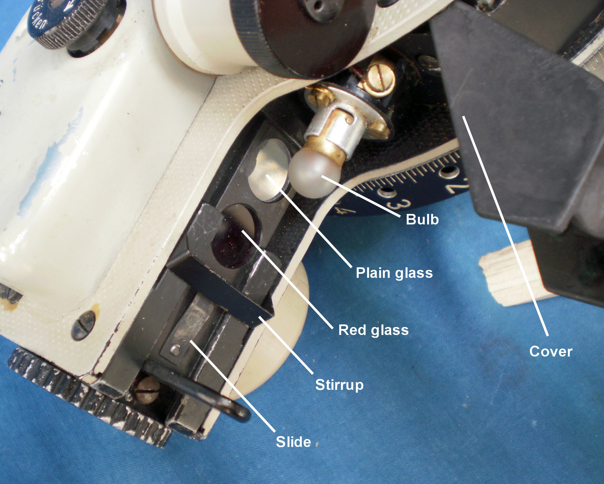
Figure 15: Bubble illumination lamp and filter slide.
In full daylight, a ground-glass screen is inserted into the socket on the front of the instrument and this can be seen in place in Figure 15. For night-time illumination or in poor daylight, this fitting must be removed and replaced by one having a 45 degree mirror to divert light from the bulb to the bubble chamber (Figure 16 and Figure 1, above)
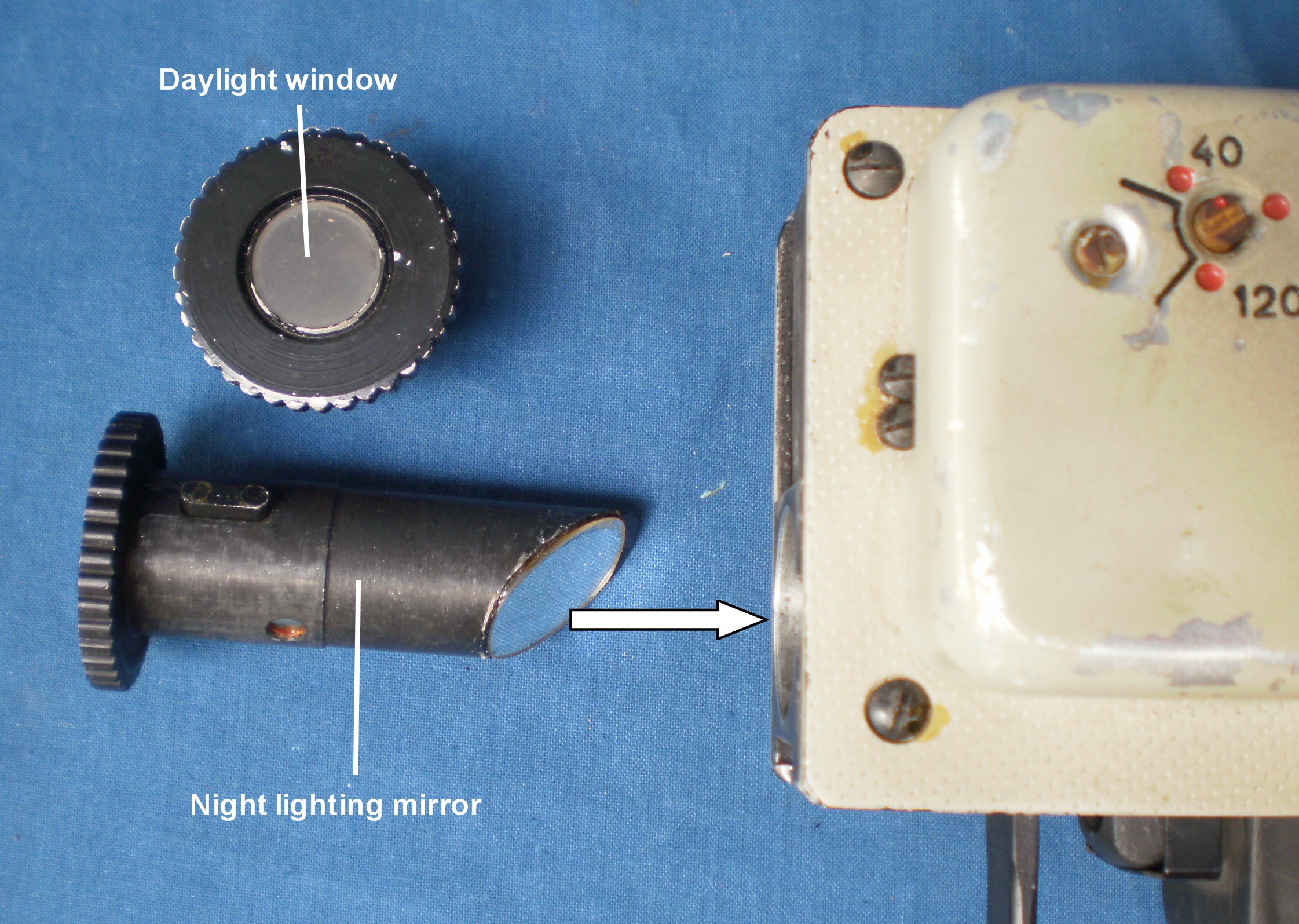
Figure 16: Fittings for bubble illumination.
b) Integrator
While the master switch must be on to obtain lighting anywhere on the instrument, the bubble chamber will not be lit until the timing unit has been wound fully. This resets the integrator so that the minutes drum is zeroed and the degrees disc set to 3 degrees. The bubble chamber remains illuminated until the end of the observation, when the front of the integrator carriage operates a switch that cuts current to the bubble lamp and switches on the current to the integrator lamp. This switch is seen at the left of Figure 10 and is shown in close-up in Figure 17.
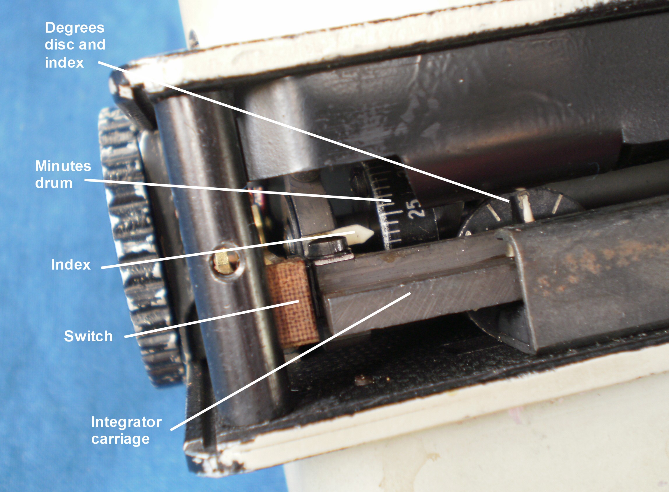
Figure 17: Integrator switch and read-out.
Removal of a thin sheet metal cover reveals the bulb and the switch wiring (Figure 17 a). The end of the bulb is painted black to limit stray light. The integrator lighting intensity is controlled by the rheostat on the right hand plate at the front of the instrument.
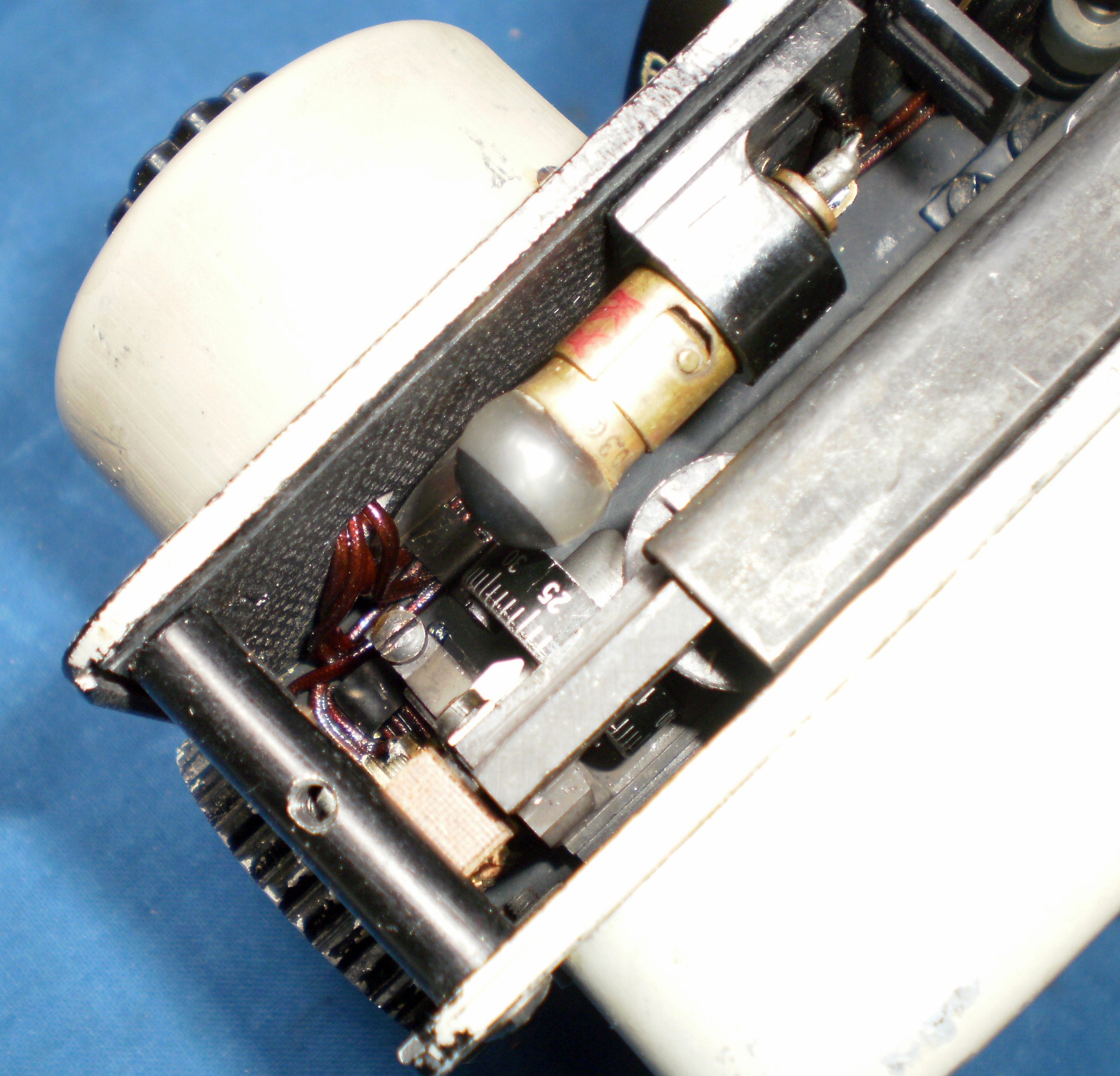
Figure 17 a: Integrator lamp
c) Other scale illumination
The tens of degrees scale and the degrees drum are lit by a lamp at the rear right of the instrument. The lamp housing is shown in close up in Figure 18. Pressing the red button switches off the integrator lighting and switches on the scale lighting.
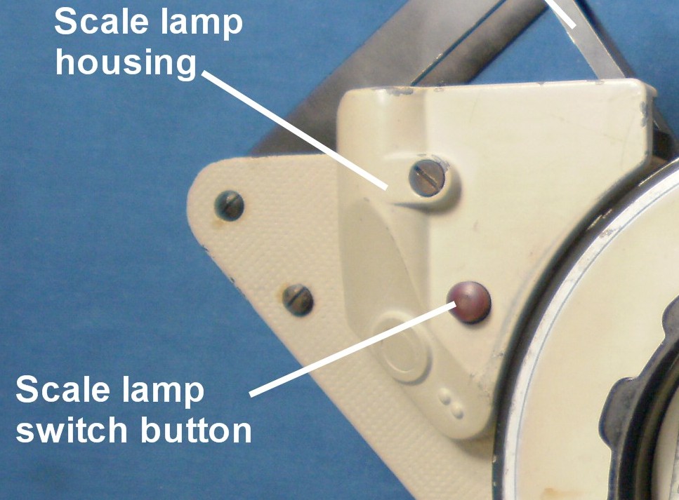
Figure 18: Scales lamp housing.
Removal of the slot-headed screw reveals the lamp fitting and change-over switch (Figure 19).
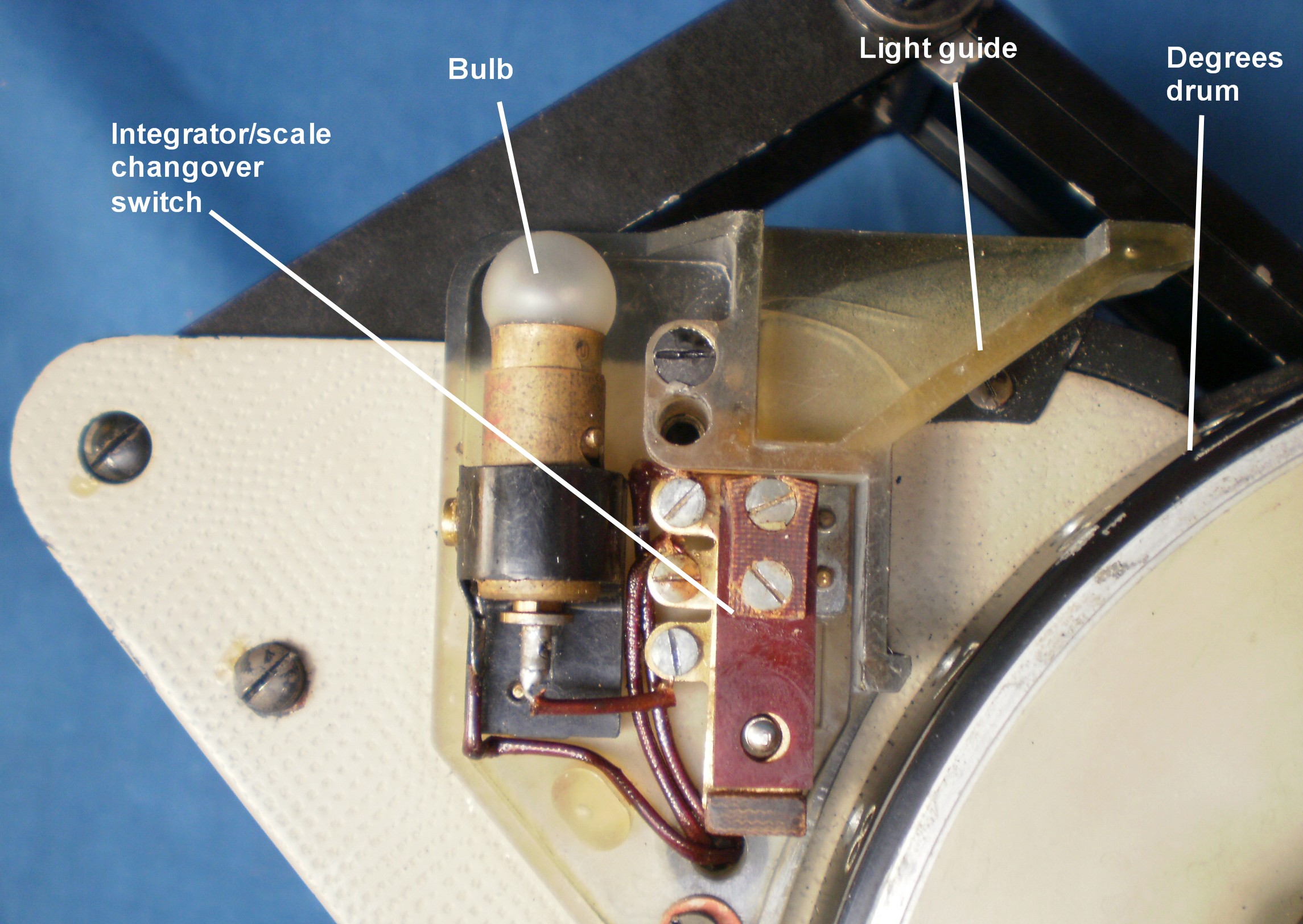
Figure 19: Scales lamp fittings.
d) Accumulator
This was a nickel-iron accumulator of two cells with a potassium hydroxide electrolyte and although the manual in giving instructions about charging refers to allowing the cells to gas after charging, the unit provided appears to be completely sealed (Figure 20), no bad thing in an aluminium alloy instrument. Potassium hydroxide, as well as corroding aluminium with great ease, also generates potentially explosive hydrogen gas.
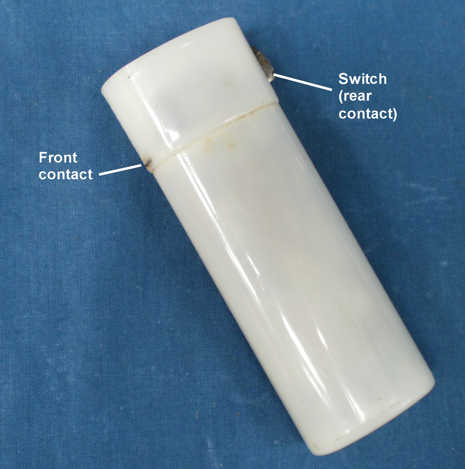
Figure 20: Exterior of accumulator.
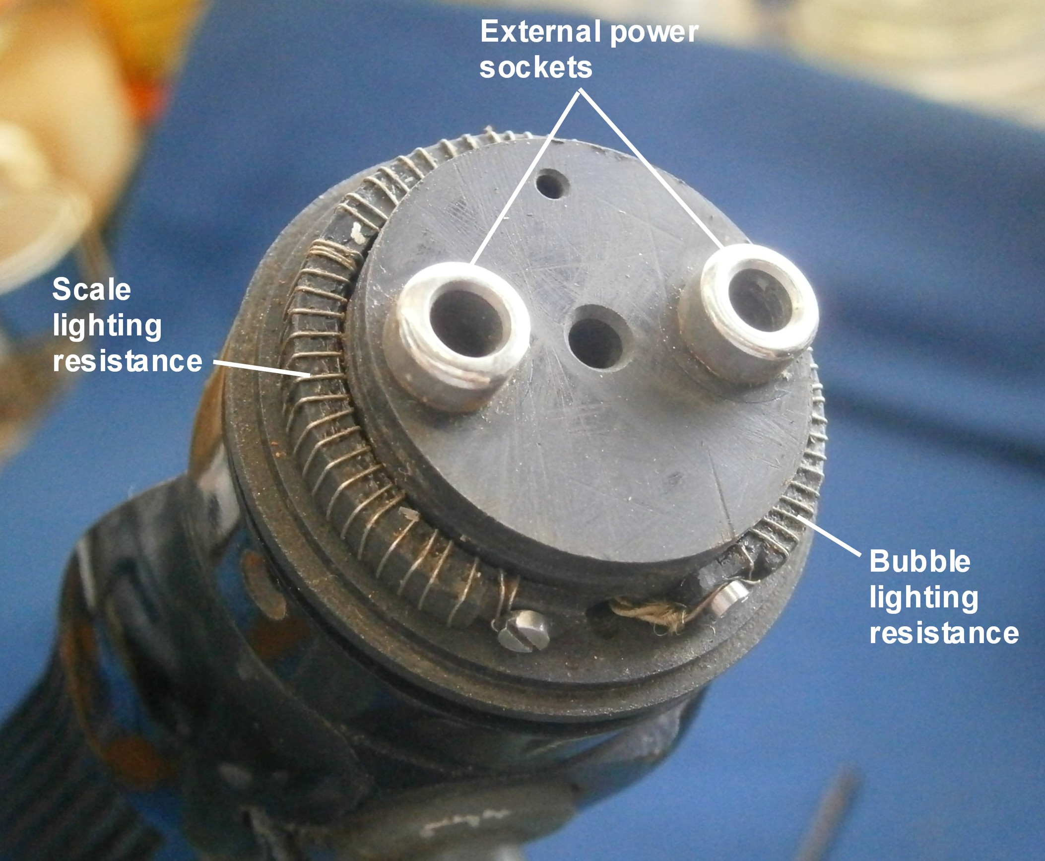
The unit appears to be a rechargeable hand torch, adapted for use in the sextant, as there is a socket for a bulb in the top and current is provided by a projection at the front and the metal switch at the rear, with internal contacts in the battery compartment. The switch plays no part in the instrument other than providing a path for current flow. The exterior of the battery housing is shown in Figure 21 and Figure 22 shows its interior. When the housing is closed, the rear contacts of the accumulator and the instrument come together, and the contact at the front of the lid makes the circuit from the switch on the accumulator via a curved brass strip only when the housing is securely closed.
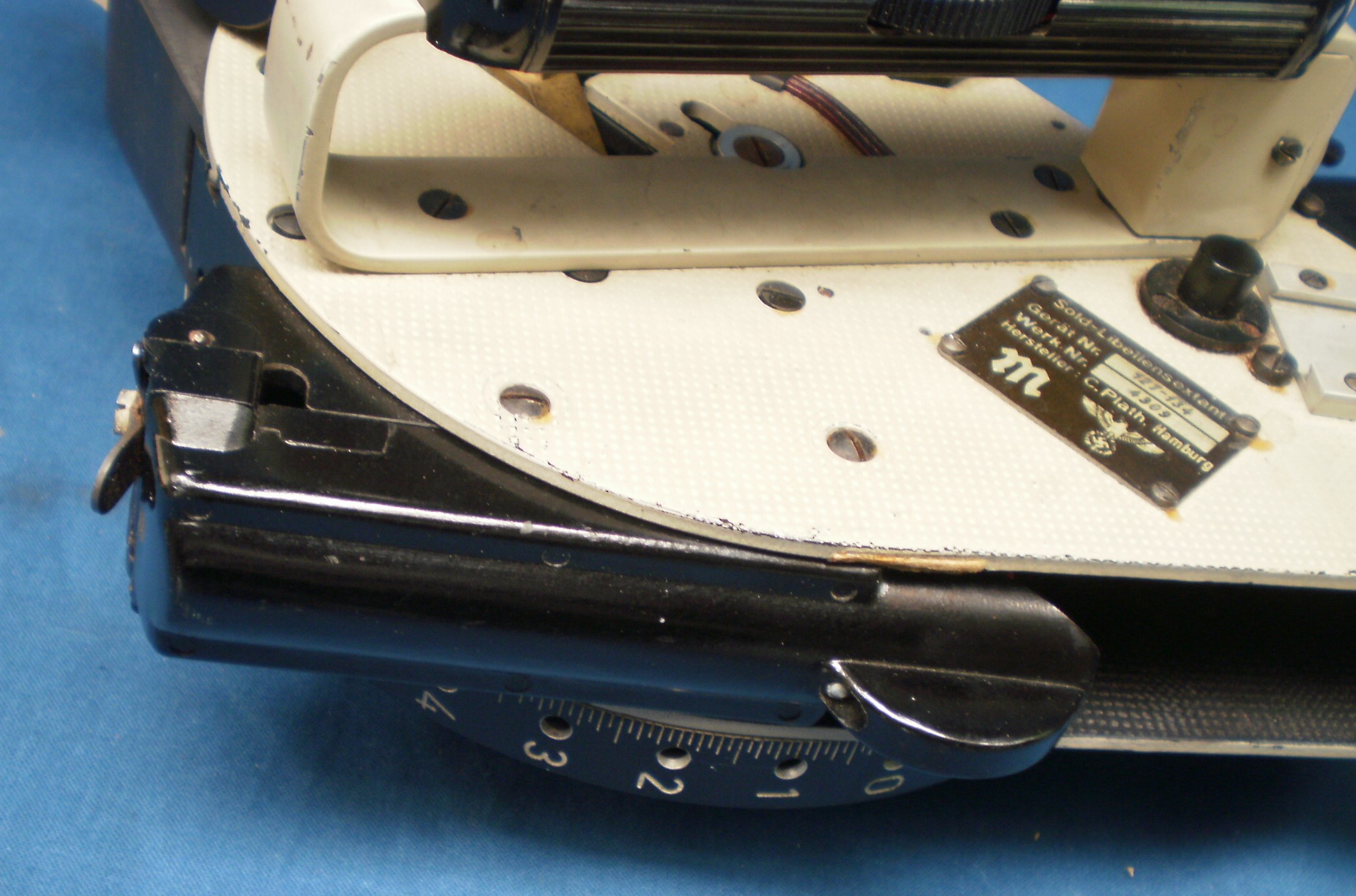
Figure 21: Exterior of accumulator housing.
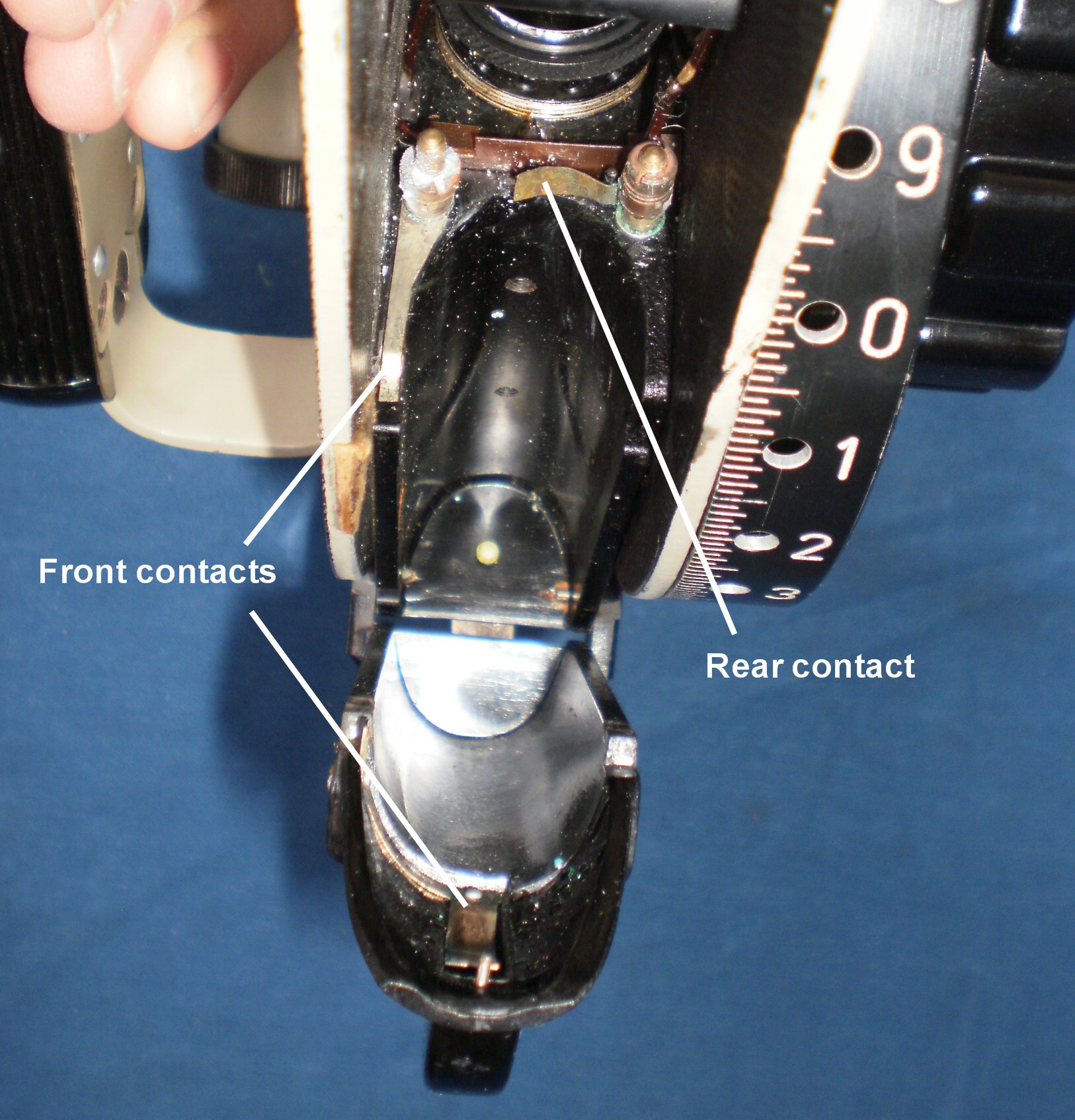
Figure 22: Contacts inside accumulator housing.
Timer
The timer at the front left of the instrument is wound by depressing the knob (Eindrücken) and winding in the direction of the arrow up to a stop. This also returns the integrator carriage to its starting position and zeroes the integrator read-out, as well as preventing the integrator lamp from being accidentally lit. The timing period may be set to 40, 120 or 200 seconds, but only when the timer is running. It is started by depressing the trigger. The movement has a pin-pallet escapement and a monometallic balance wheel (Figure 20). The escape wheel has three set of teeth on its periphery. A different set is moved into the path of the pallets for each timing period.
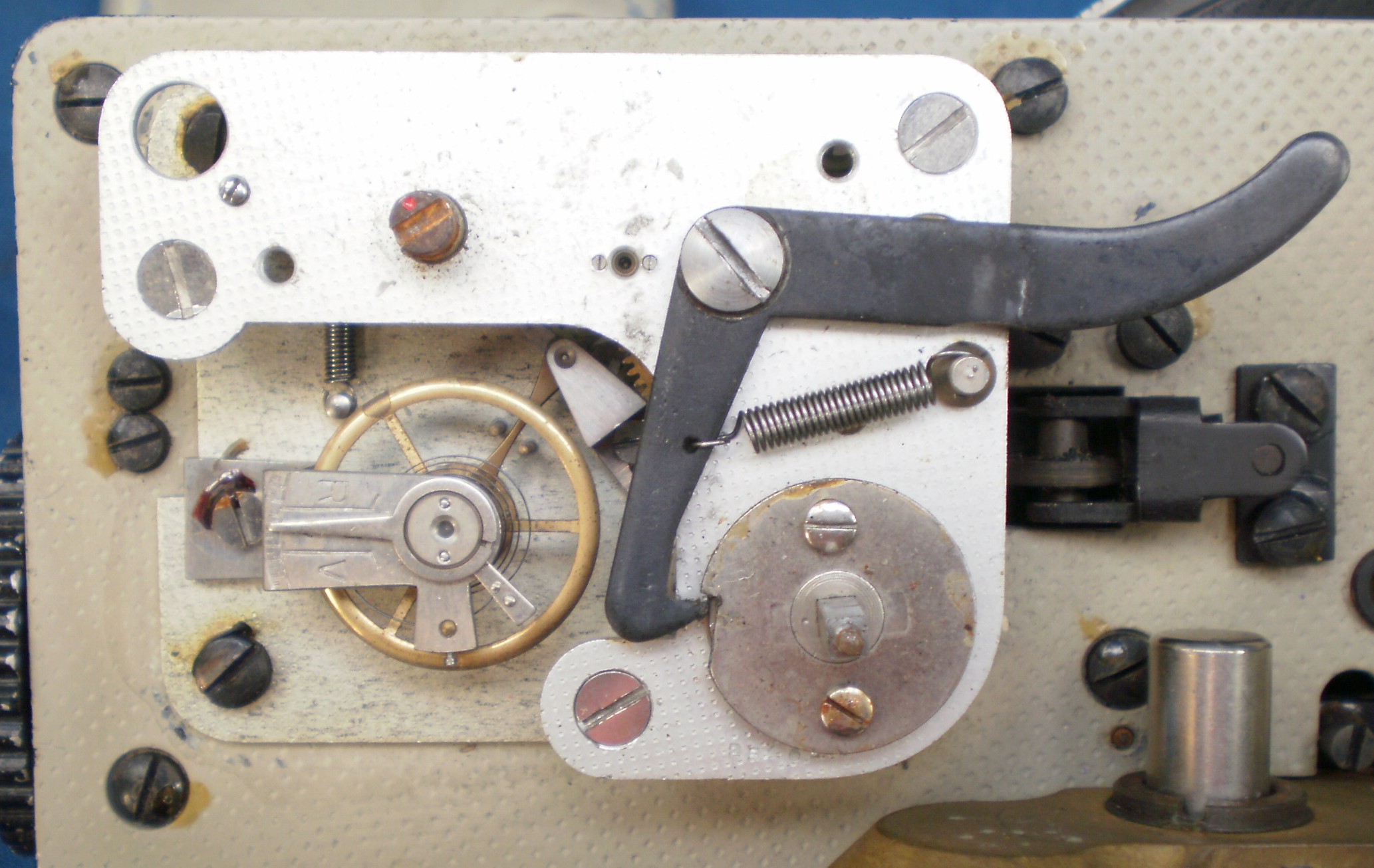
Figure 23: Timer movement
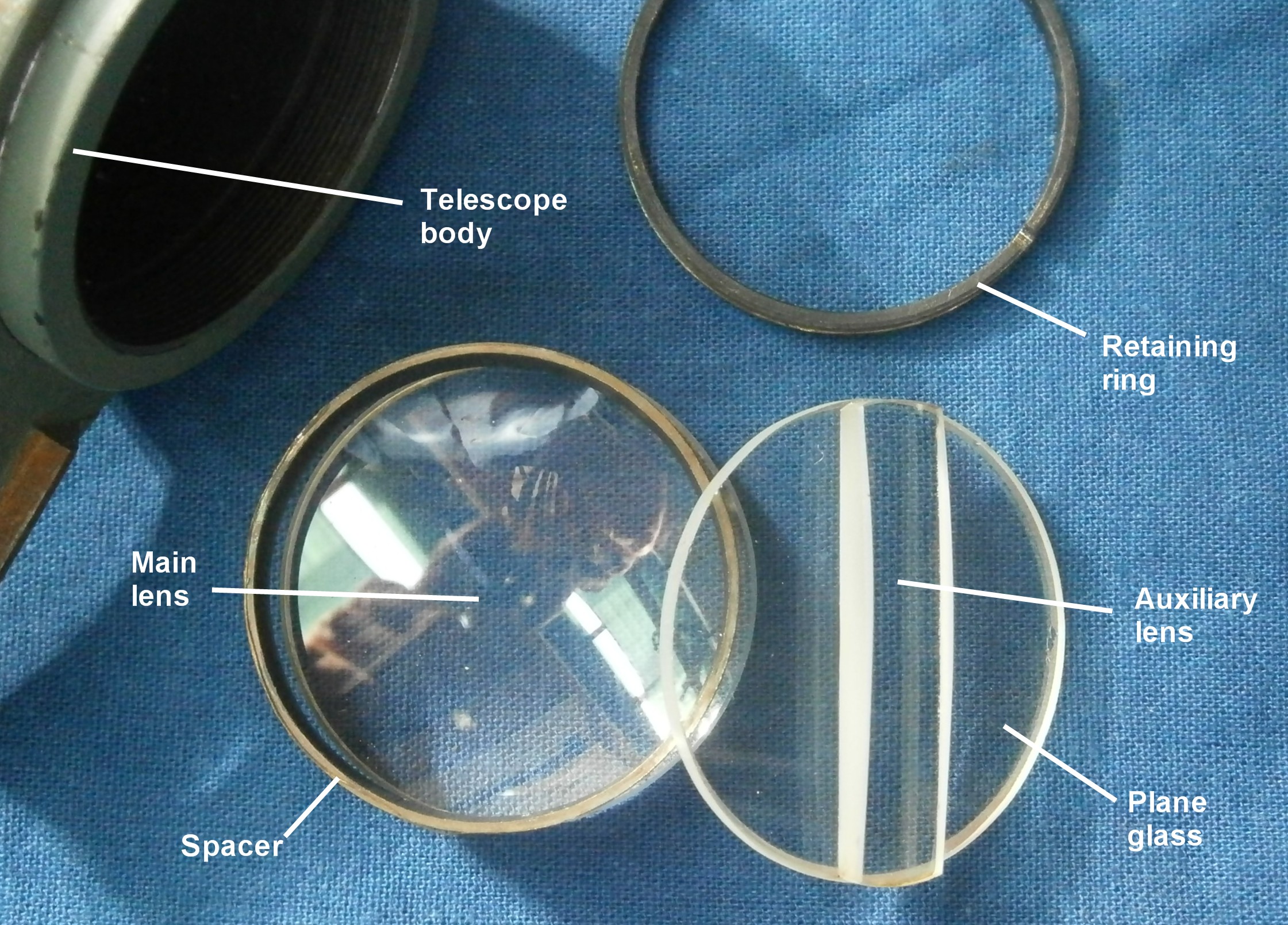
Telescope
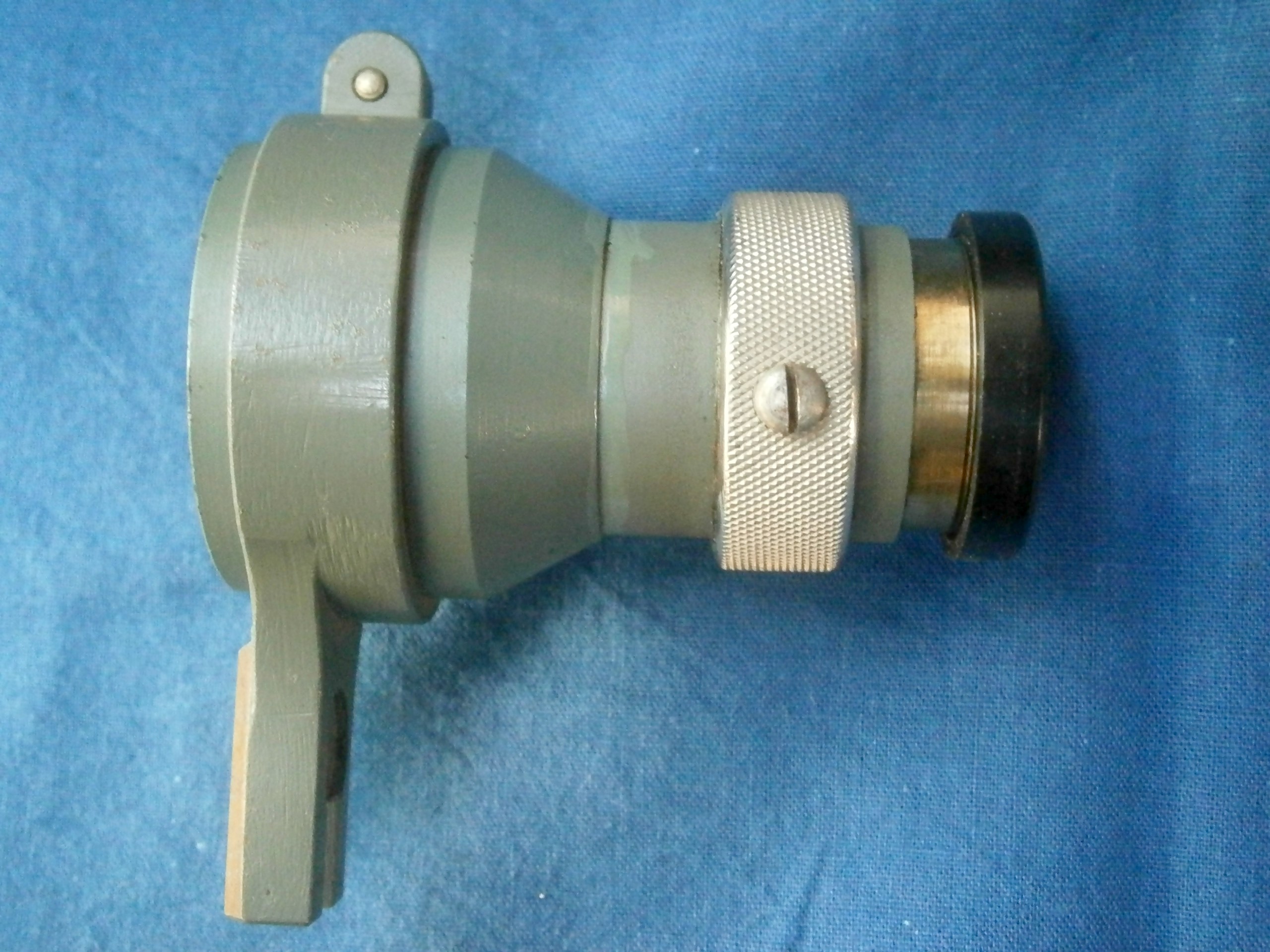
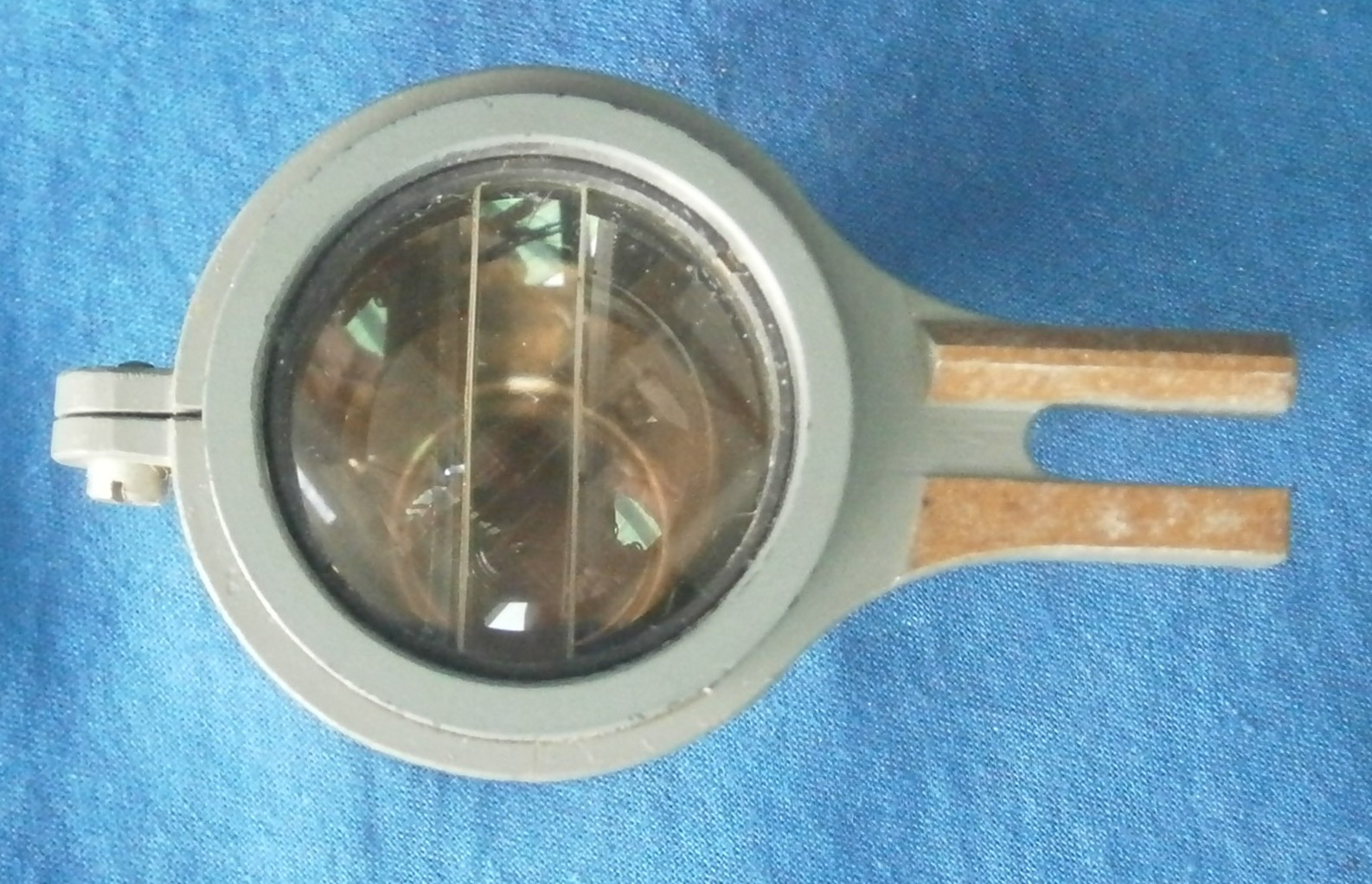
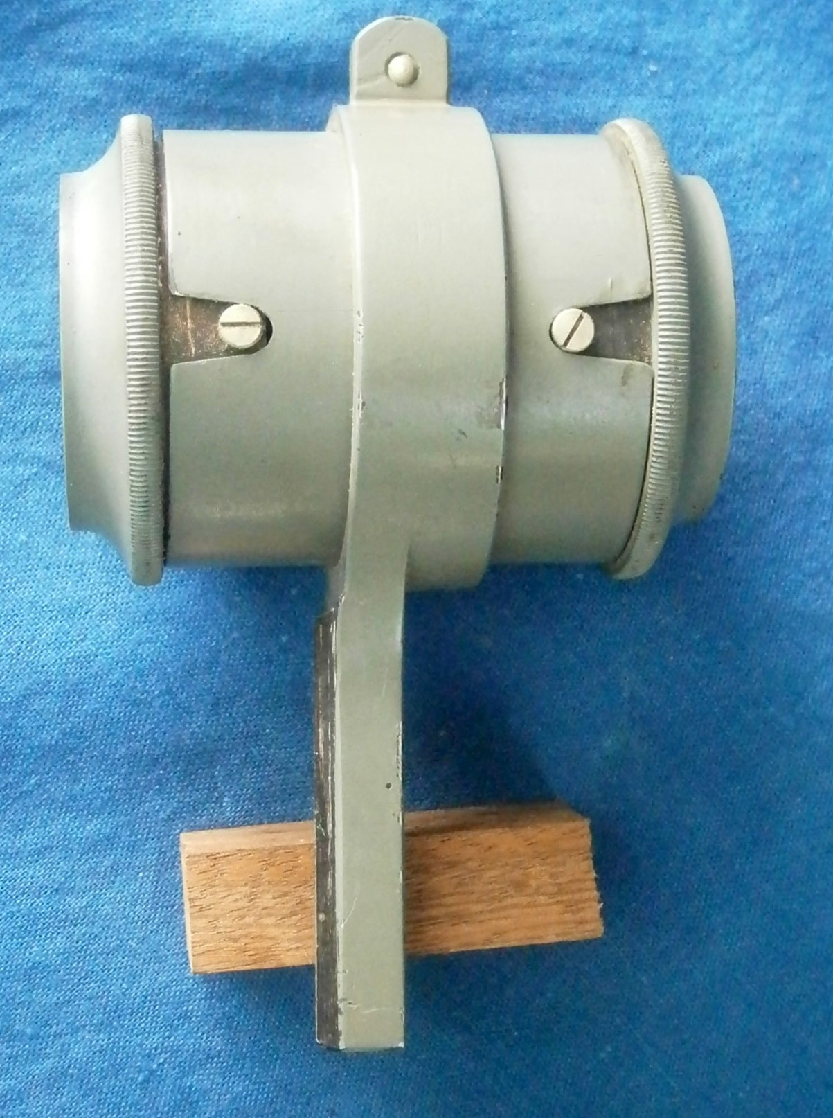
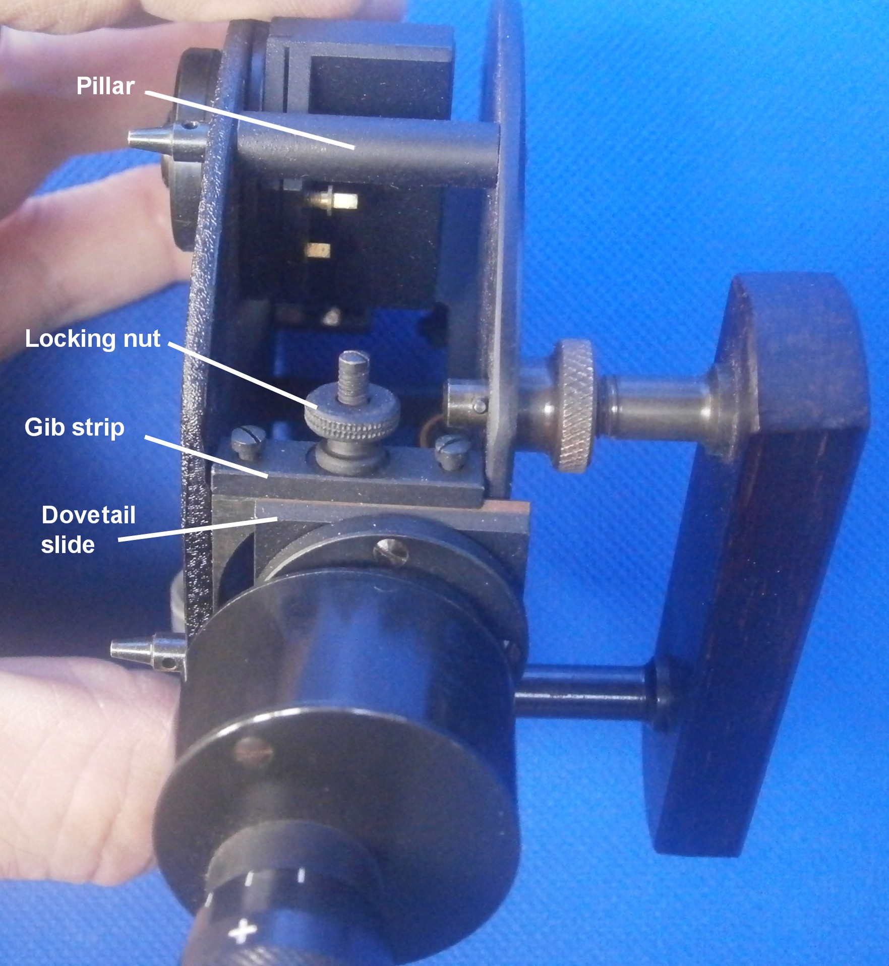
This is s short Galilean telescope of 2 power and has an objective aperture of about 28 mm, for use in indirect observations of fainter stars such as Polaris, increasing its apparent brightness by a factor of two. The recommended procedure for the inexperienced was to locate the star by direct observation and get approximate coincidence of star and bubble, before changing to indirect observation using the telescope. The telescope is focussed by rotating the objective mounting and is located in a dovetail slide on the left side of the instrument (Figure 24). It cannot be used for direct observations.
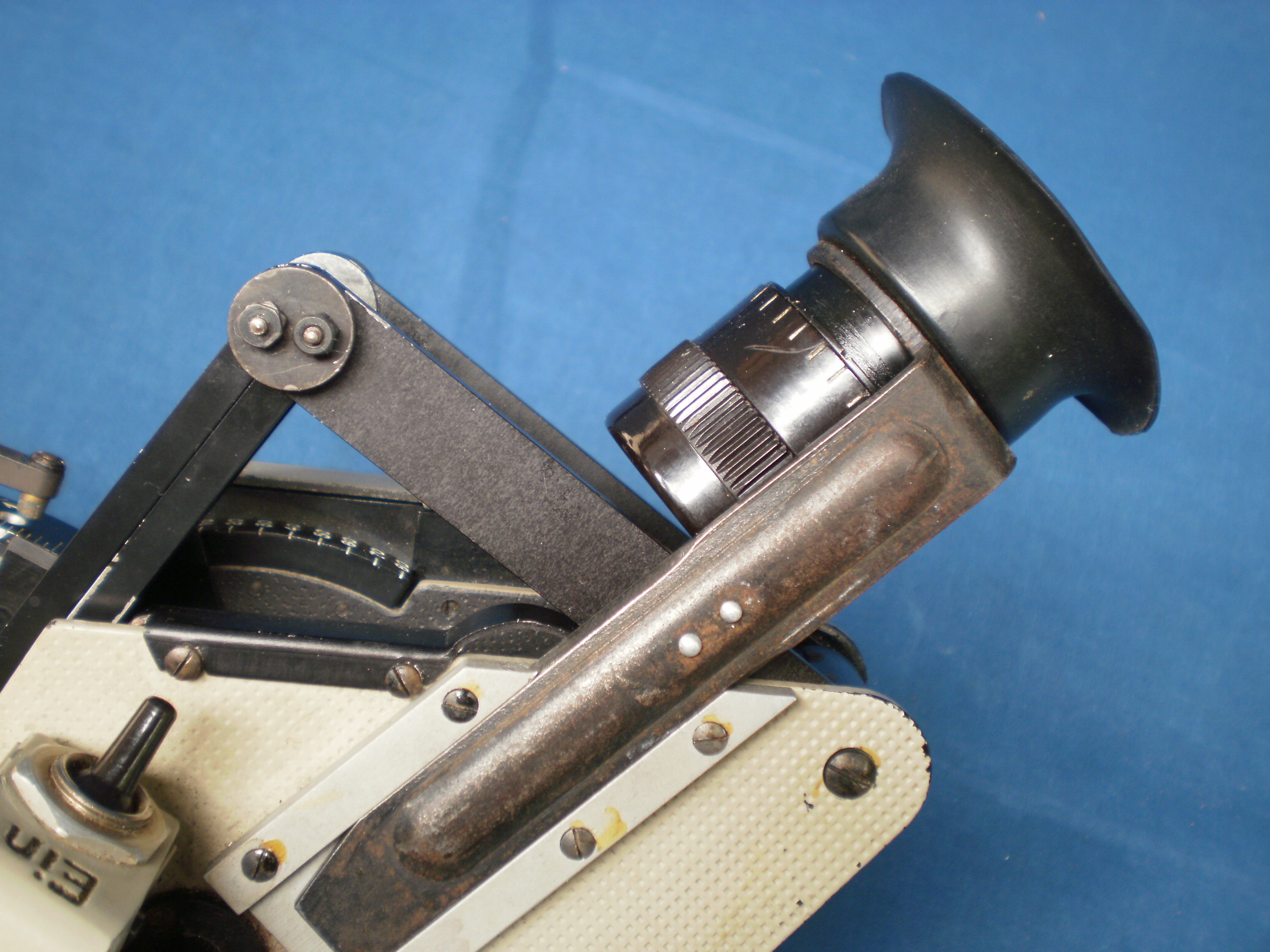
Figure 24: Telescope in place.
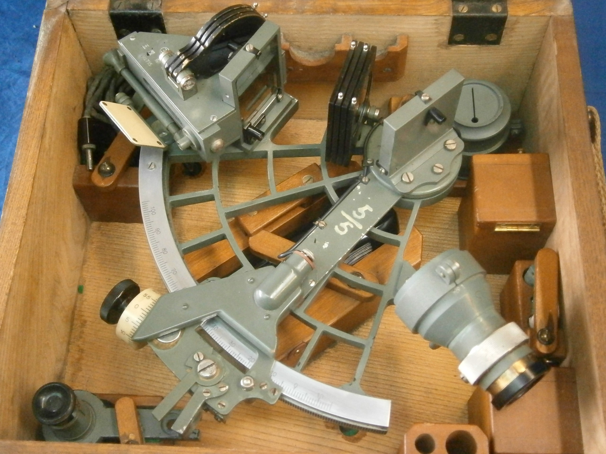
Case
The exterior of the sheet- metal case is shown in Figure 25 and its interior in Figure 26 (These are courtesy of Alan W Heldman).
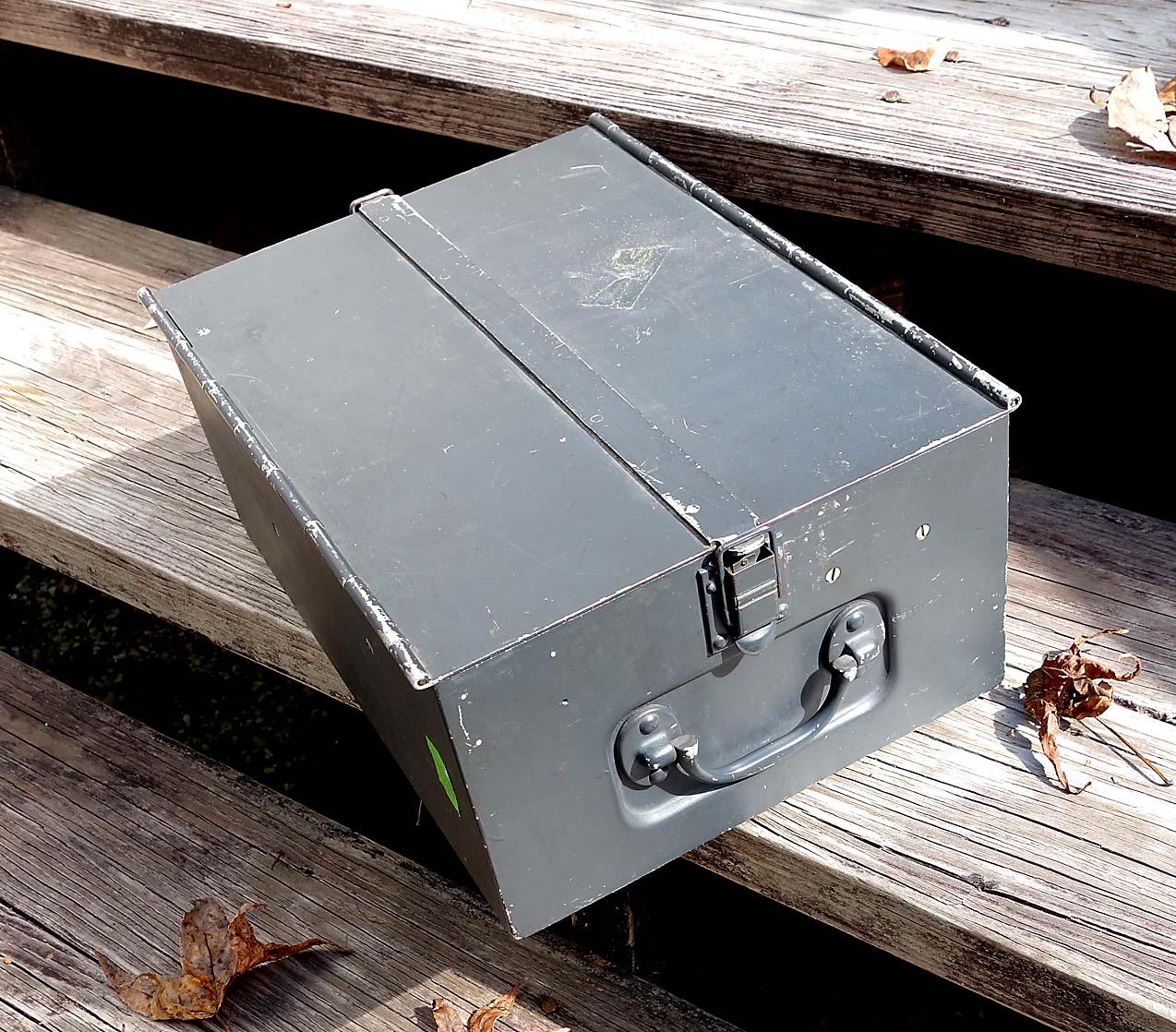
Figure 25: Exterior of case.
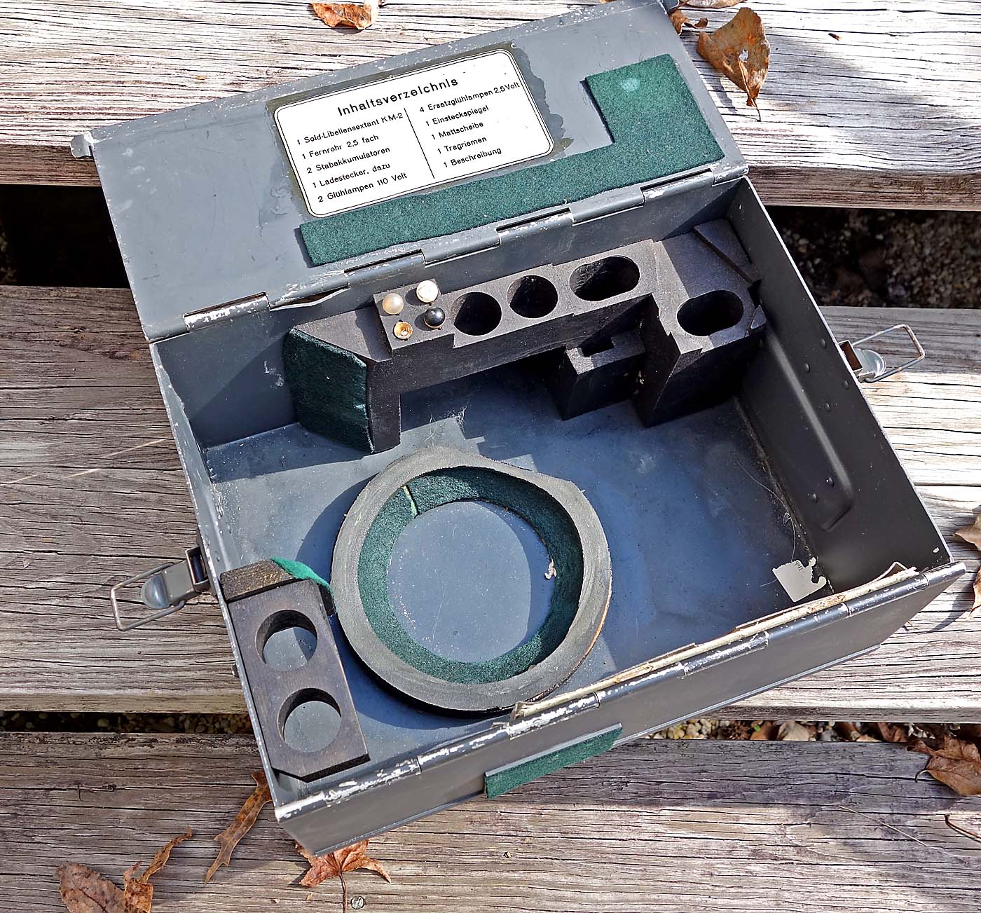
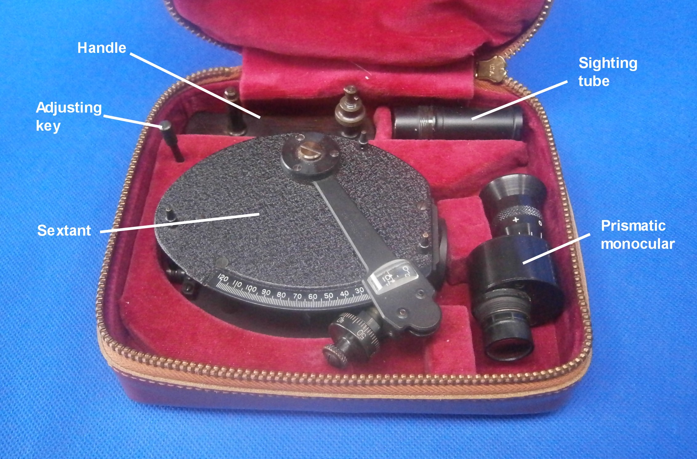
Figure 26: Interior of case.
The two oval pockets are for accumulators, two of the large round pockets are for 110 volt blue incandescent lamps used for dropping the 110 volt DC ship-board current to one suitable for charging the accumulators, two of the large round pockets are for the ground- glass screen and mirror for bubble illumination (Figure 16), the rectangular slot is for the telescope, and four spare bulbs can be seen in place. The instruction manual is in a celluloid pocket at the front. The case also contains a charging adapter and lead, and a suspension strap, unlikely to be used aboard a ship.
The case measures 150 x 250 x 250 mm and weighs 2 kg. The instrument itself weighs 2.6 kg.
Operating instructions
The following is translation of an extract from the 1944 “Beschriebung und Bedienungsvorschrift für den SOLD-Libellensextanten KM2”. I hope that those more expert in German than I will forgive any solecisms.
II Operating Instructions.
a) Daytime observations
1) Remove the instrument from the case with the left hand and insert the ground glass screen into the opening below the integrator.
2) While holding the instrument with the top edge horizontal, find the bubble and adjust its size so it appears somewhat larger than the sun (about 1/3rd of the distance between the squared lines in the field of view). The bubble control of the level is on the left of the instrument. Set the size of the bubble by tilting the front upwards a little so that the bubble sits over the triangle in the field of view. The triangle marks the correct place as well as giving a guide to the correct size. Return the instrument to horizontal and rotate the control back a little to the left to prevent further bubbles entering the bubble chamber.
3) Transfer the device to the right hand, supporting it for better balance with the little finger under the level lamp housing. Wind the movement with the left hand by pressing in the winder and rewinding up to the stop. Set the running time by pressing down the starting lever and adjusting to the desired running time. Then rewind the clockwork.
4) Point the instrument in the sun’s direction and rotate the right knob until the sun appears in the field of view. Engage the clutch when the sun and the bubble are together in the field of view. The inexperienced may find it easier to first locate the sun by the direct observation method.
5) With a finger of the left hand, press down the clockwork starting lever and at the same time call out “Zero” to the note taker.
6) While the clockwork is running one should try constantly to keep the bubble and the sun at the same height, i.e. to keep one alongside the other.
7) If there is no note-taker at hand, then the time of observation is taken when the clockwork has run down. The observer then has to count off seconds from the observation time to obtain the time reading and deduct this from the reading time. The time is then recorded with the note “e” to indicate that it was the end point of the observation that was noted. The half of the time set on the clockwork should also be recorded at this time, as this will be deducted from the end time to obtain the averaged time of the observation.
b) Night time observations.
1) Remove the instrument from the case with the left hand and install the telescope and level lighting mirror.
2) Remove the accumulator from the case and carefully install it in its housing. Open the lid only to 20o as there is otherwise a risk of damage to the hinge. Turn the switch in the left handle to the “Ein” (on) position.
3) As for daytime observations (wind clockwork).
4) The observer must make sure that the integrator lighting resistor is set to dark. The bubble field is made visible by rotating the resistor in the left-hand handle upwards with the thumb.
5) As for (2) in daytime observations (bubble setting).
6) View the star directly through the observation mirror and turn the right-hand hand wheel until the bubble and the star are in near alignment. Then engage the clutch.
7) Operate the clockwork trigger and carry out the observation as under 5, 6 and 7 for daytime observations.
c) Reading the average height.
Reading is as described on page 13. The basic reading on the degree drum is added to the integrator reading.
Figure 8: Reading the Integrator.
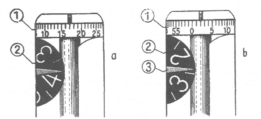
1 Minutes drum
2 Degrees wheel
3 Degrees wheel index
Example: Clock time, end of observation 22h 11m 38s, running time of clockwork 40 sec, index error 0’. The reading gives:
Tens scale 50 o
Degrees drum 8o
Integrator degree wheel in 4 division 4o
Minutes drum 17’
Observed altitude 62o 17’ (see Fig 8a)
The relevant time of this observation is determined as follows:
Half time run -20s
Clock time 22h 11m 38s
Time = 22h 11m 18s
Next calculation as usual
Because of backlash, it is possible for the degrees wheel to indicate in the area of 2 degrees while the minutes wheel is already above zero (Fig 8,b). In this case, if the minutes wheel indication is past zero, take the higher degrees figure and if below zero, the lower.
Werner Luehmann has kindly provided the following comments and photographs of his Luftwaffe version of the SOLD:
As an owner of an “aircraft SOLD sextant” I can say that the only differences between the KM 2 an the aircraft version are: (1) left handle (also the orientation of the off/on switch is perpendicular), (2) accumulator (navy) versus a 3 Volts battery (air force) or optional a flying lead with in integral resistor to reduce the on board voltage, (3) the case (wooden box for aircraft type). Also, (4) the aircraft sextant is missing the “suspension bracket” (although there was a gear available to suspend it in the aircraft). There are neither obvious other differences in parts, nor any in “sealing”.
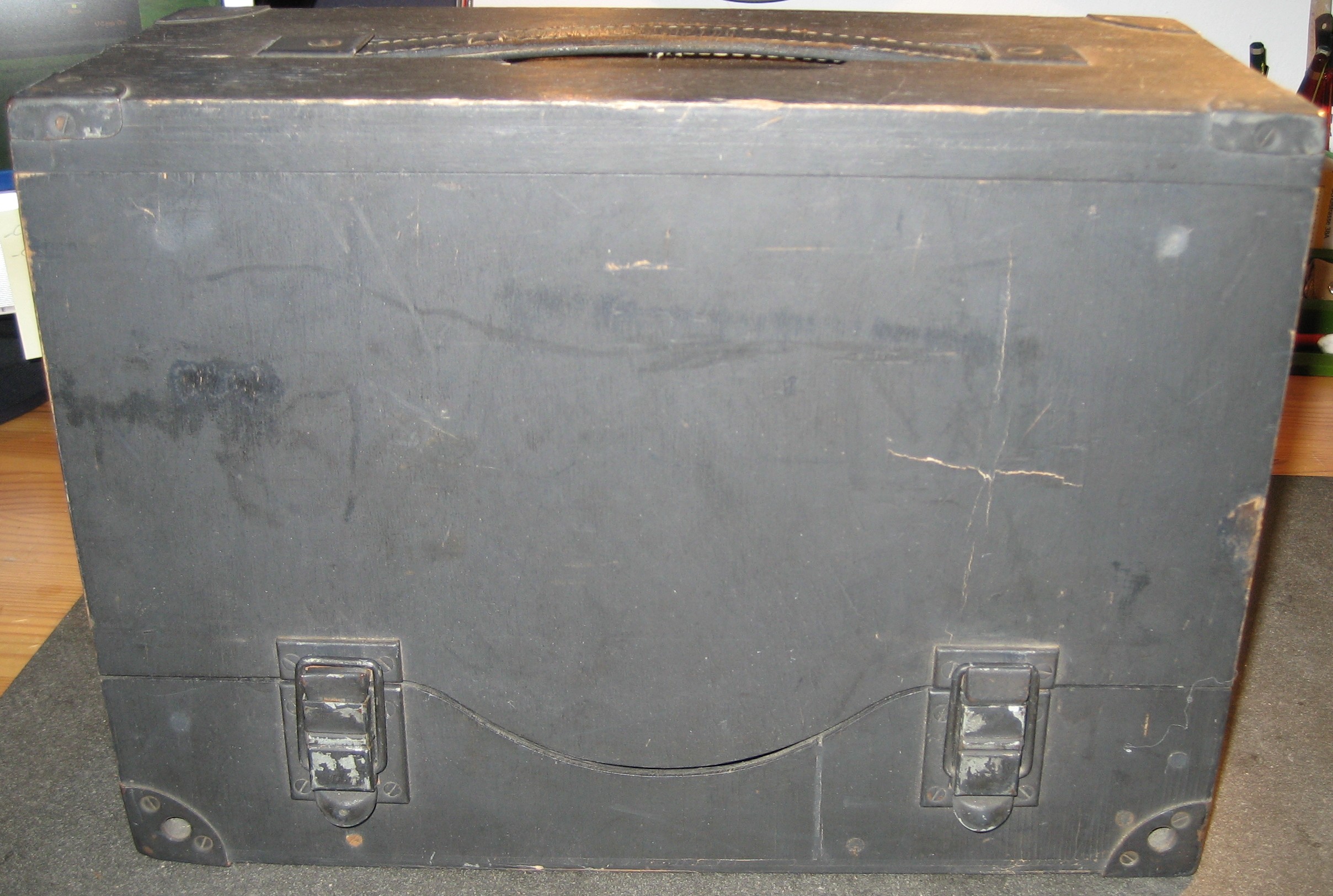
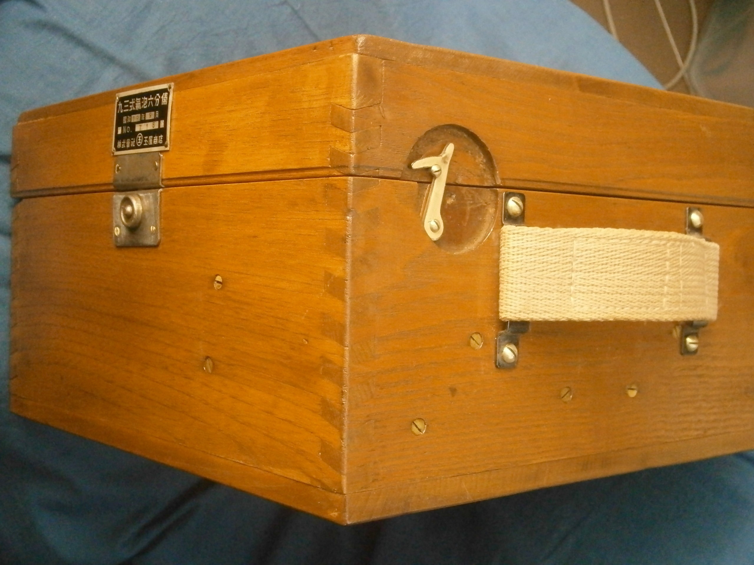
Figure A1: Exterior of wooden case.
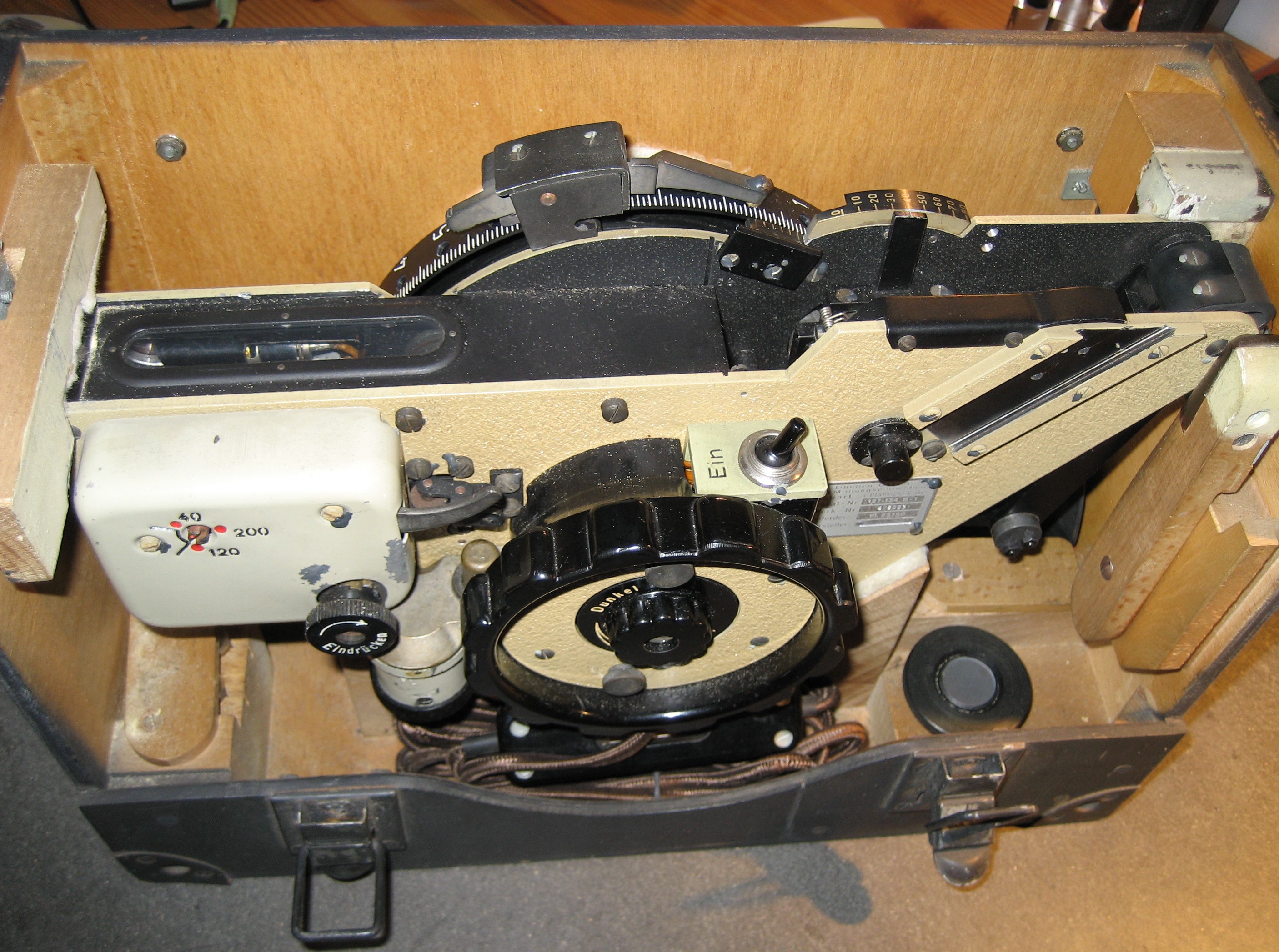
Figure A2: Luftwaffe instrument in case.

Figure A3: Instructions in lid.
I wish also to acknowledge the kindness of Alan W Heldman in entrusting me with his SOLD sextant, for sending me a copy of the operating manual and for providing encouragement as I struggled with the translation. I am happy to provide interested readers with the whole translation, which includes the original illustrations. “Contact me” if you would like a pdf file of the translation. I make no guarantee as to its accuracy.
MORE ABOUT THE SOLD
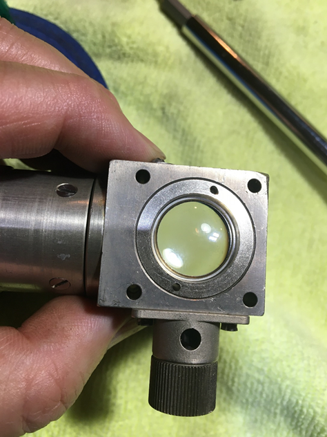
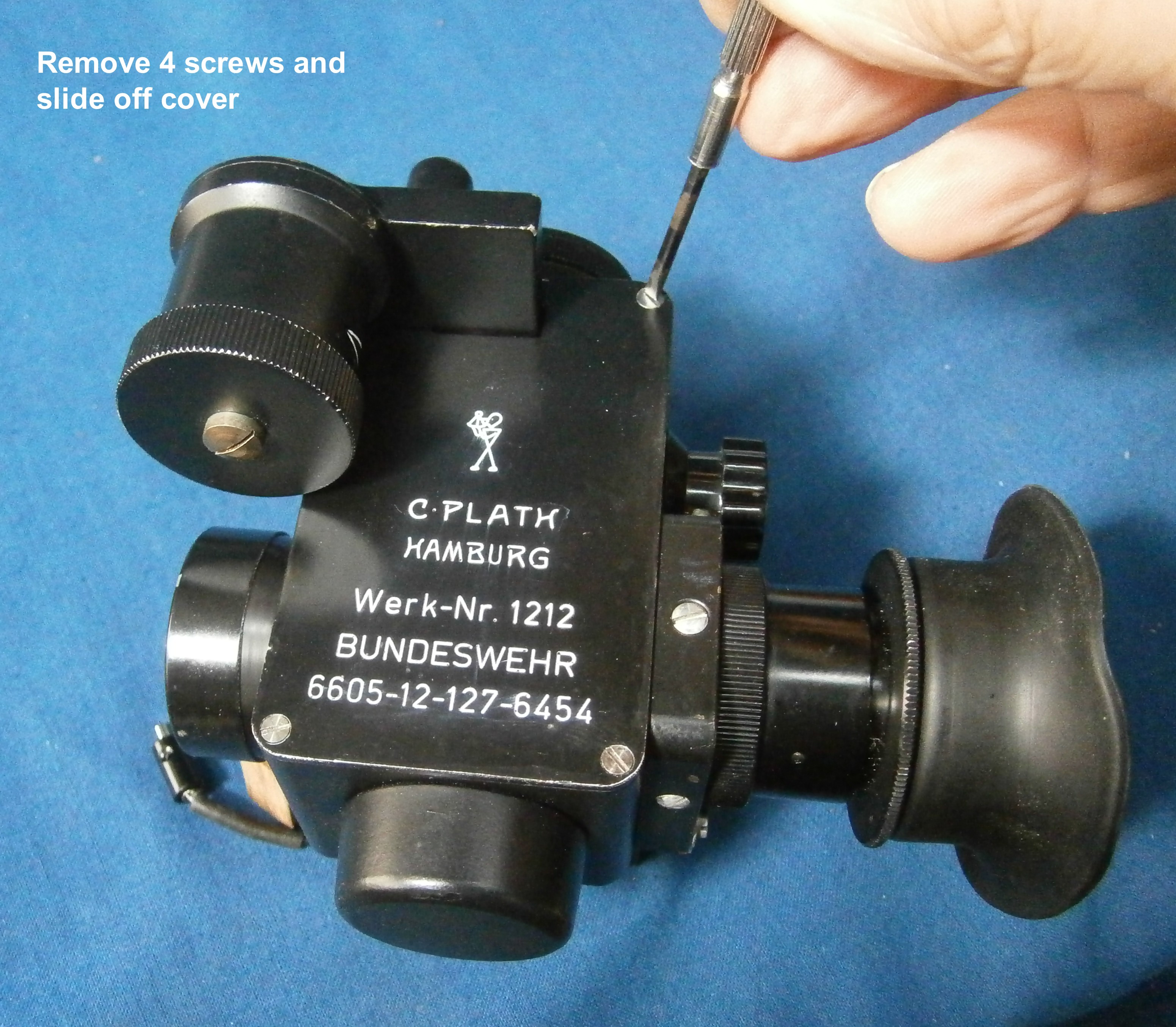
Recently, Wolfgang Koeberer kindly entrusted me with his KM2 Bubble Octant, allowing me to delve a little more deeply into this interesting instrument. His was not in as good condition as that of Alan Heldman and the optical path was rather dirty.
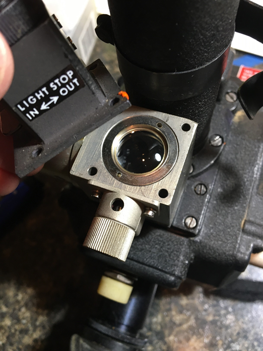
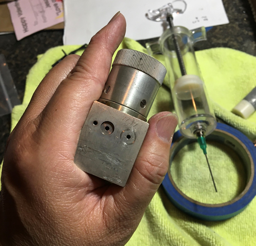
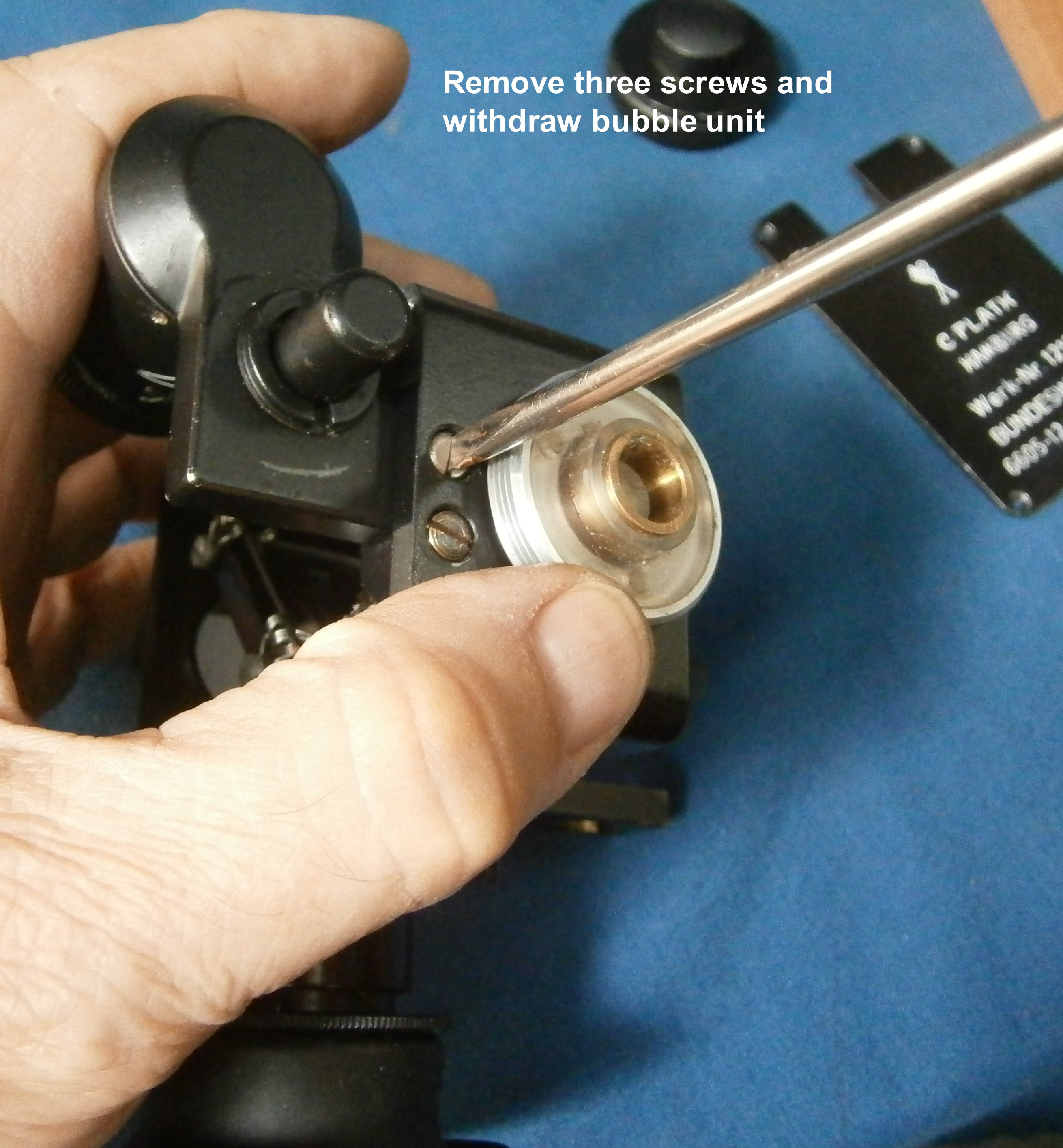
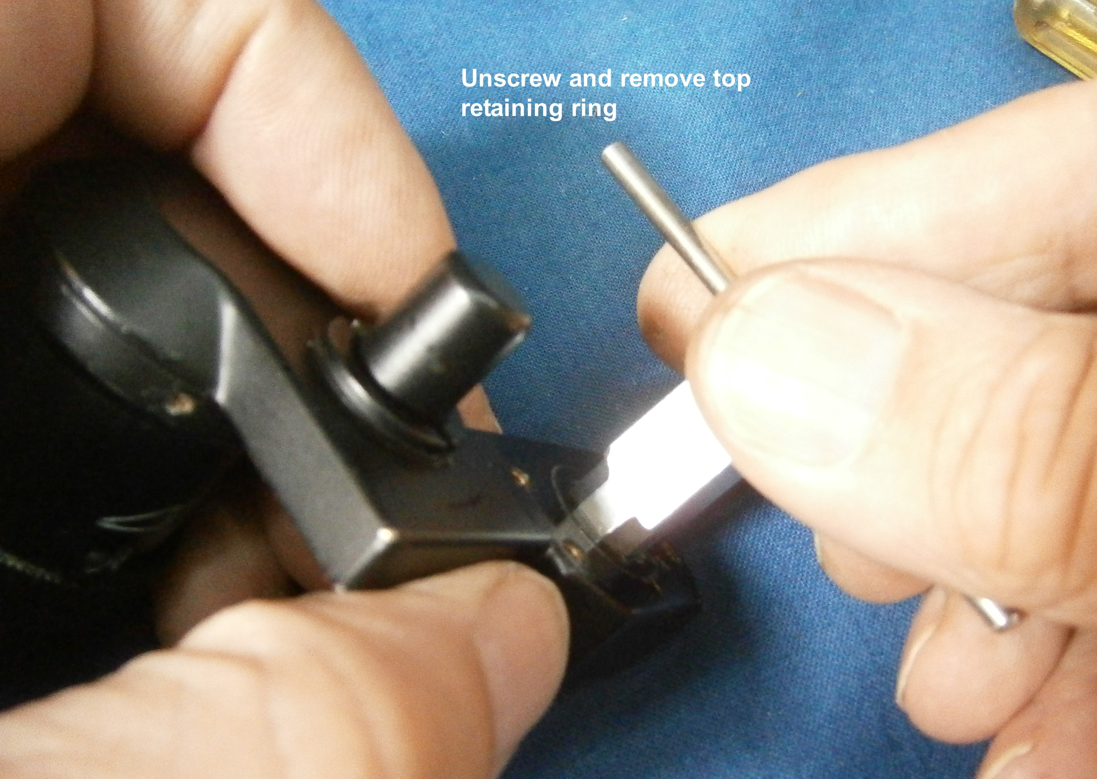
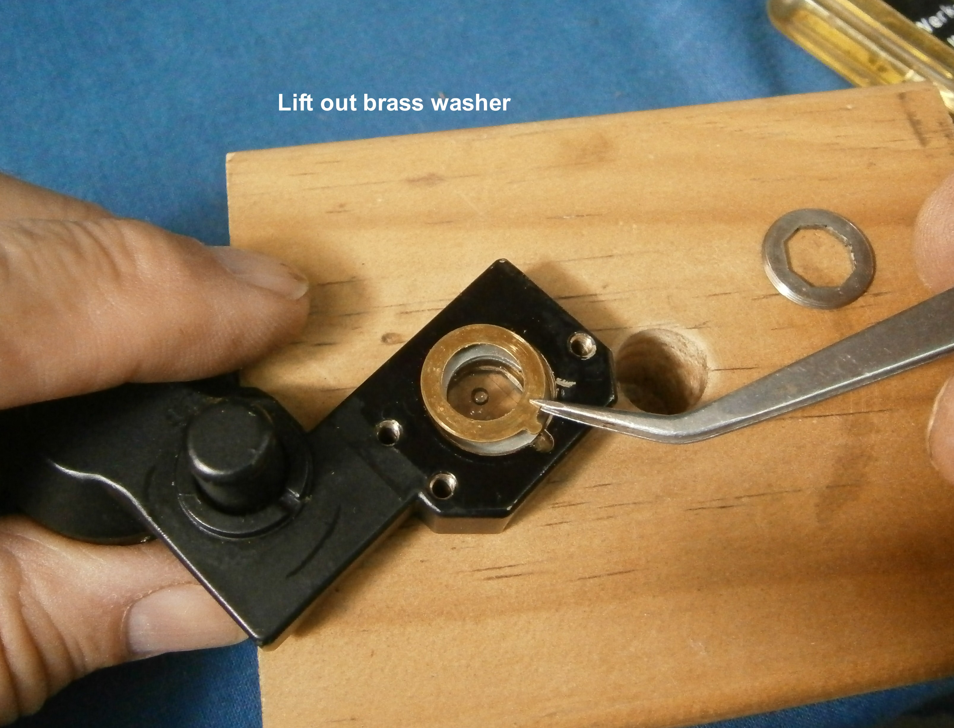
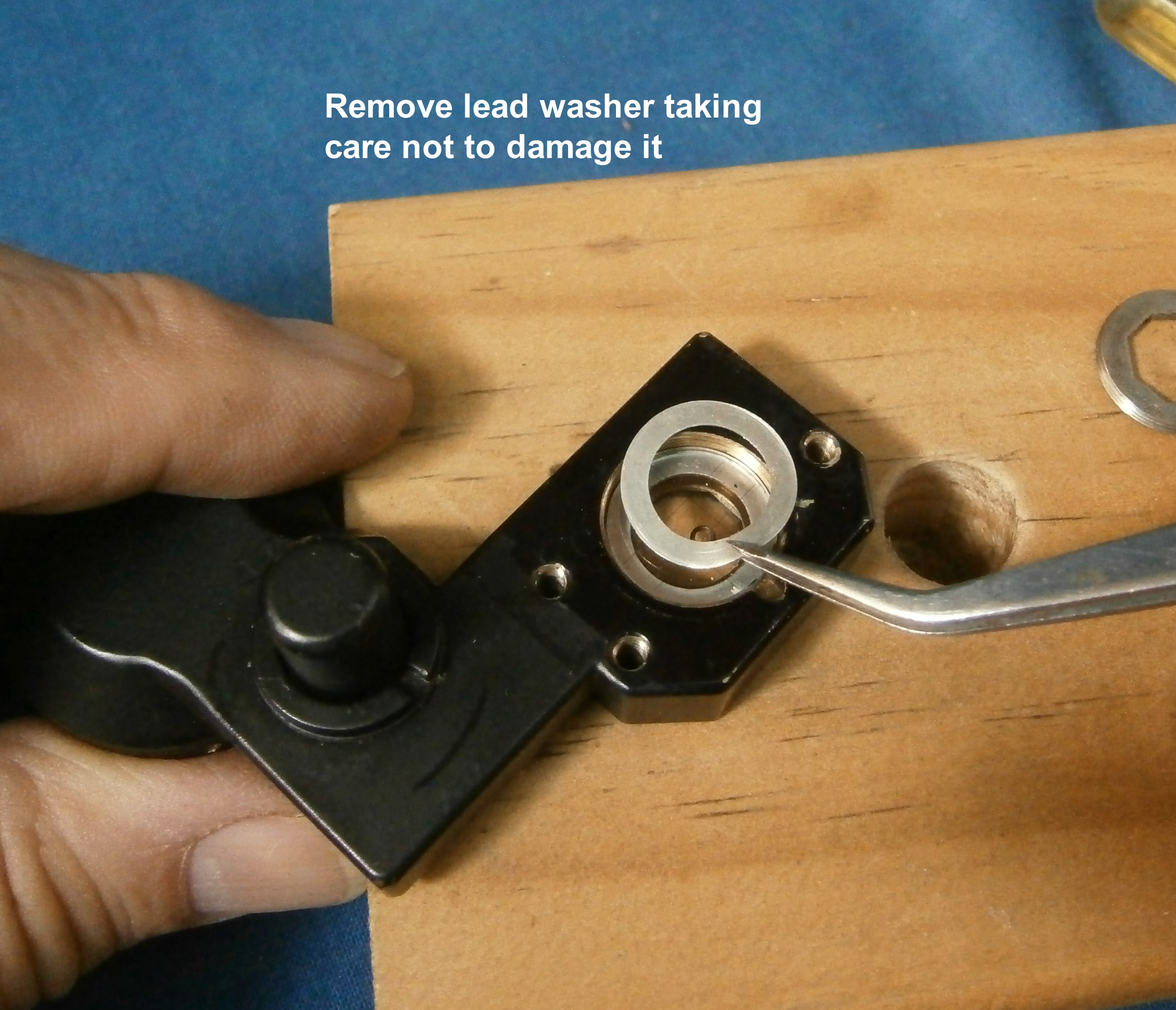
The bubble unit was still full and intact, except that particles could be seen floating in the fluid, so my first act was to remove the bubble unit from the instrument to clean the exterior of the glasses. Apart from the floating particles, the view through the bubble unit was then clear, so I did not attempt to remove the glasses. Rather, I gained access to the interior by removing the air chamber and cycling the control until no more fluid would come out. A note of caution is needed here. When I opened the chamber, there was a faint smell of onions. Incautiously, I took a good sniff of the fluid to try to identify it and spent the next five minutes with burning nose and watering eyes. The skin on the front of my wrist, where a few drops had fallen then began to itch and burn. Plainly, if this was alcohol, the authorities had been serious about denaturing it to defeat the ingenuity of sailors in obtaining access to alcohol. On reflection, I think the fluid was probably di-methyl sulphoxide. The Soviet IMS3 sextant, a development of the SOLD, fills its chambers with alcohol, so I flushed out the unit several times with isopropanol, flushing out most of the particles in the process and removing I hope most of the vicious fluid previously present.
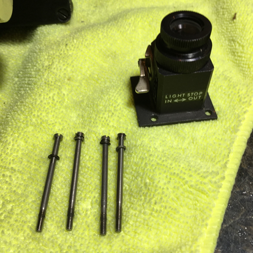
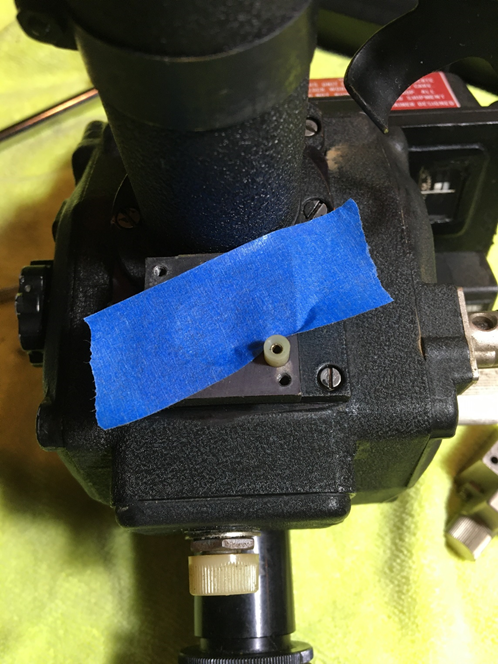
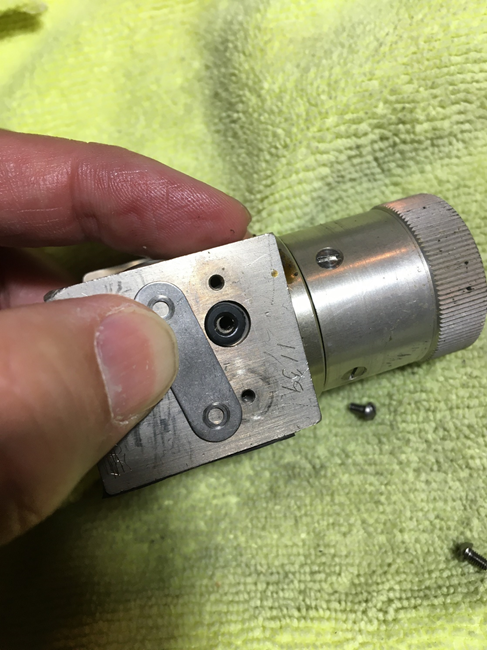
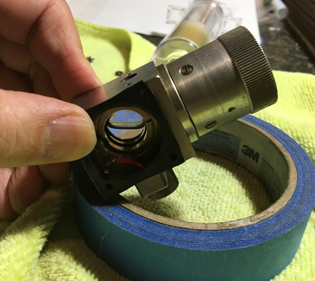
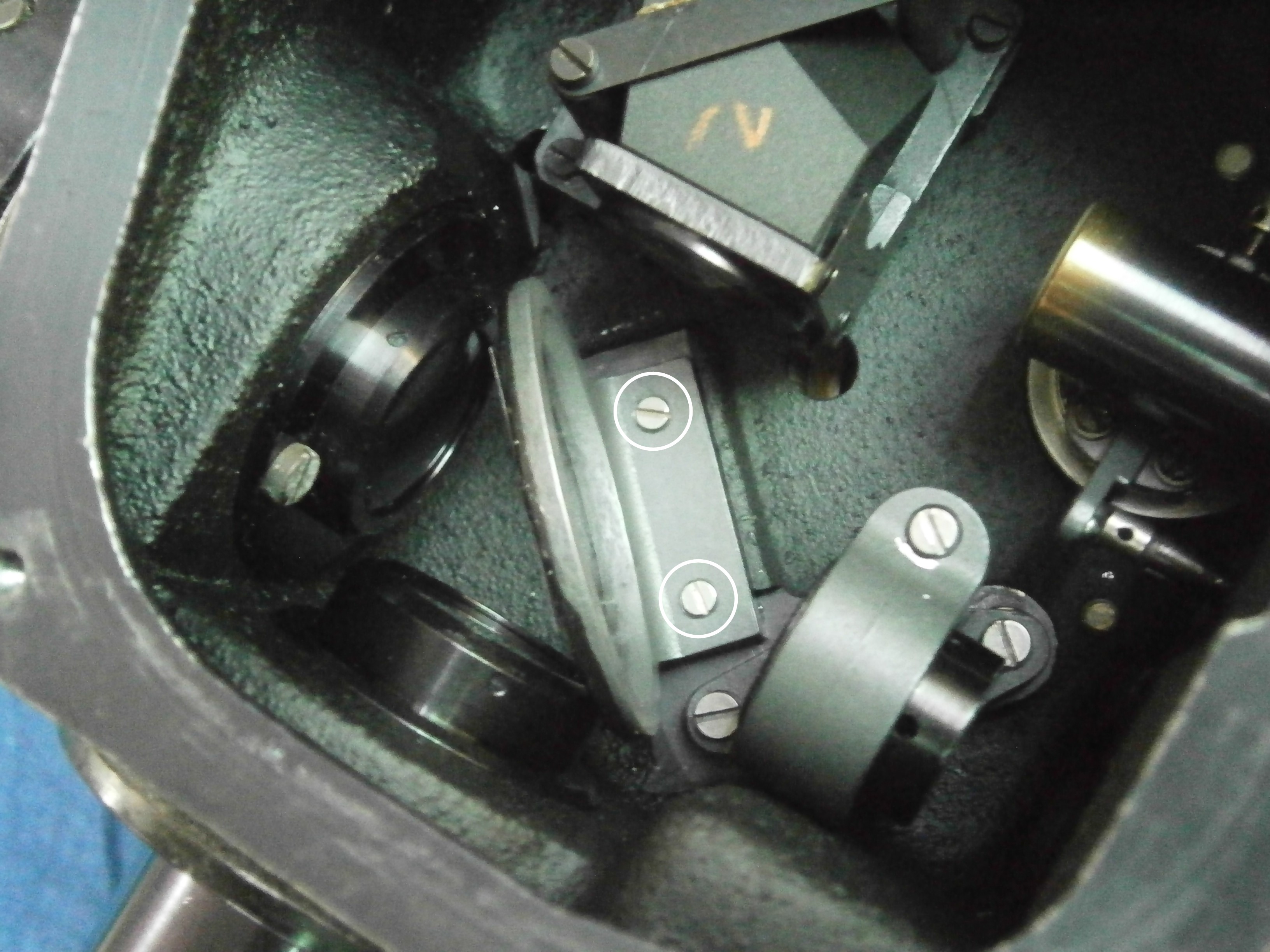
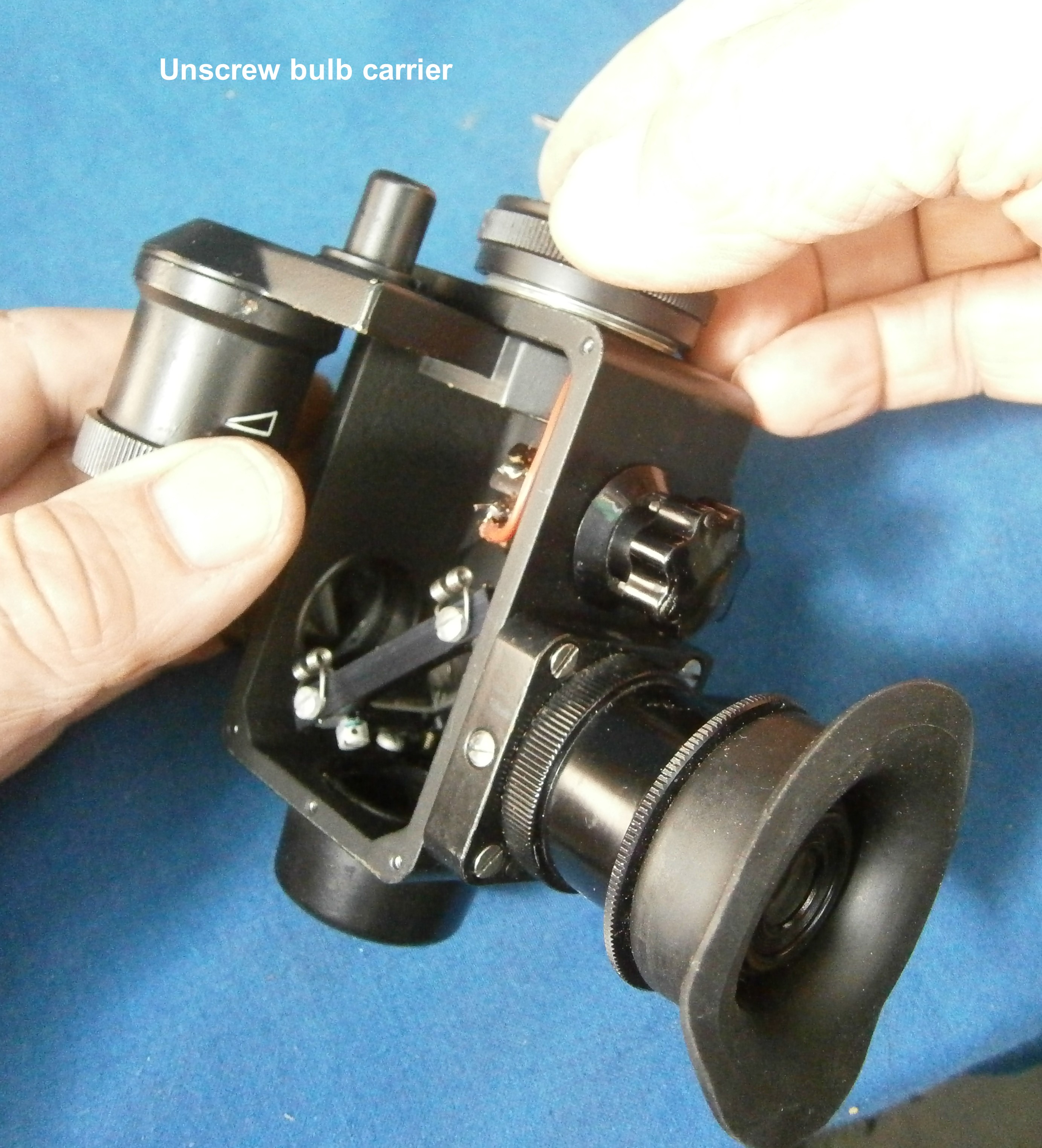
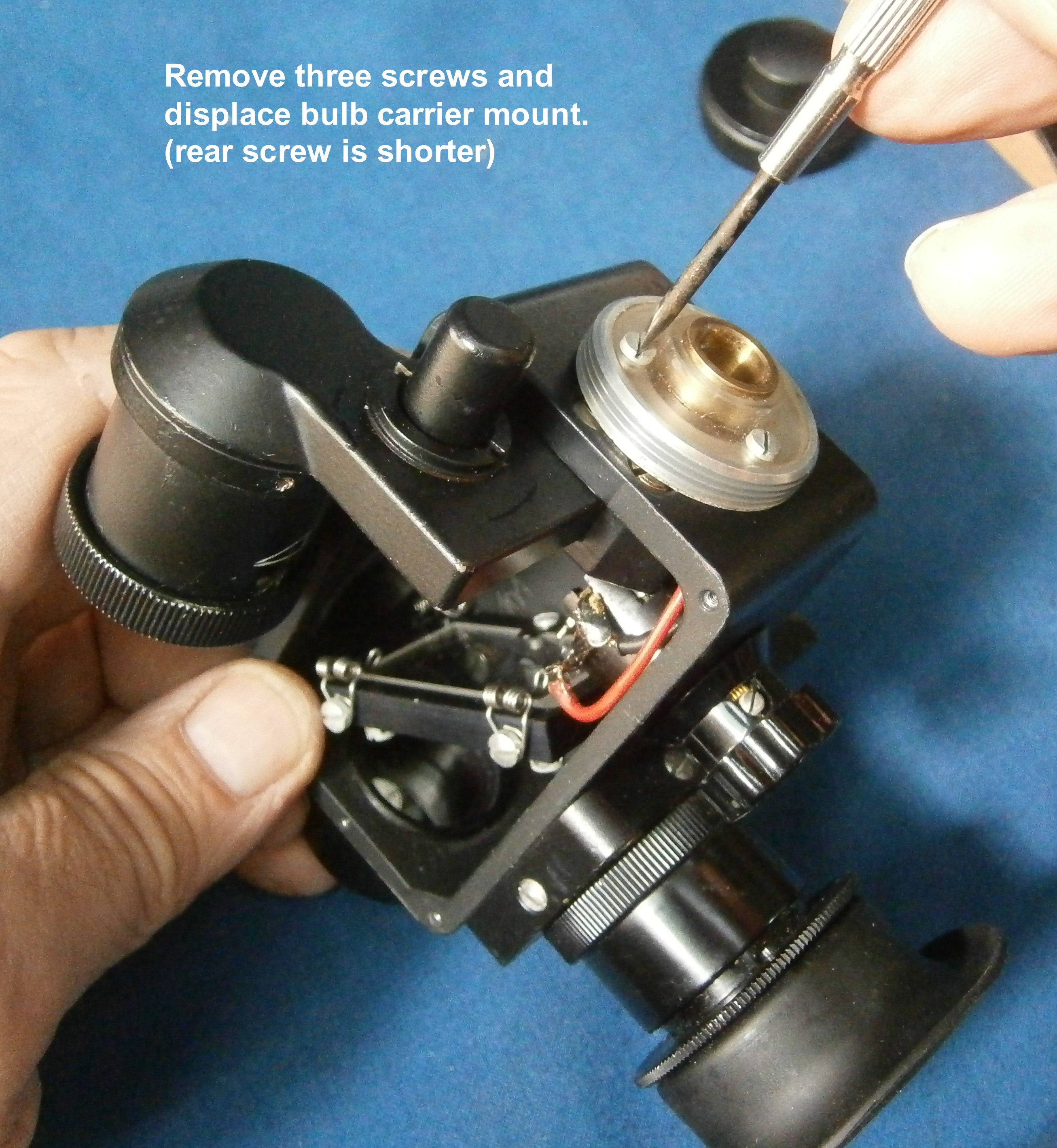
On replacing the bubble unit, I found that there was no view through the instrument and there was a a rattle when it was gently shaken. On removing the bubble unit again, it became clear that the mirror labelled “6” in Figure 1 above, had detached itself from its mounting. Getting at the mounting involved some serious deconstruction of the instrument and Figure 27, below, shows its extent. I will not go into details except to remark that most people, I suspect, if they were to remove the integrator unit, might, like me, begin to despair of ever getting it back into place.However, removing the integrator unit allowed me to overhaul it an get the roller to move freely again.

Figure 27 : Access to first mirror.
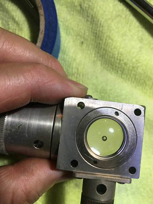
With the mirror glued back on to its bracket , the bracket replaced and all the other parts necessary to be removed having been replaced, another viewing through the sextant showed that, while there had been some improvement, there were still many particles in the field of view. The mirror labelled “3” in Figure 1 I suspect is not a mirror at all but a pentaprism. At any rate, the glass surface immediately below the bubble chamber is horizontal. Cleaning it and the upper surface of the objective lens (“4” in Figure 1) brought about no improvement, so I suspect inaccessible silvered surfaces of the pentaprism, or mirror, if it is a mirror, have deteriorated. Getting at this area would have involved removing the whole left plate of the sextant and I was not prepared to take the risks involved. However, the flecks of dust or damage do not affect the function.
None of the electrical system worked, but this was relatively easy to solve by accessing all the electrical switch and bulb contacts and cleaning them. I also soldered in a battery carrier for 2 AA cells that fits comfortably into the original battery compartment.
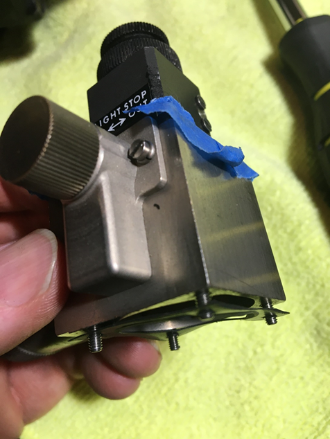
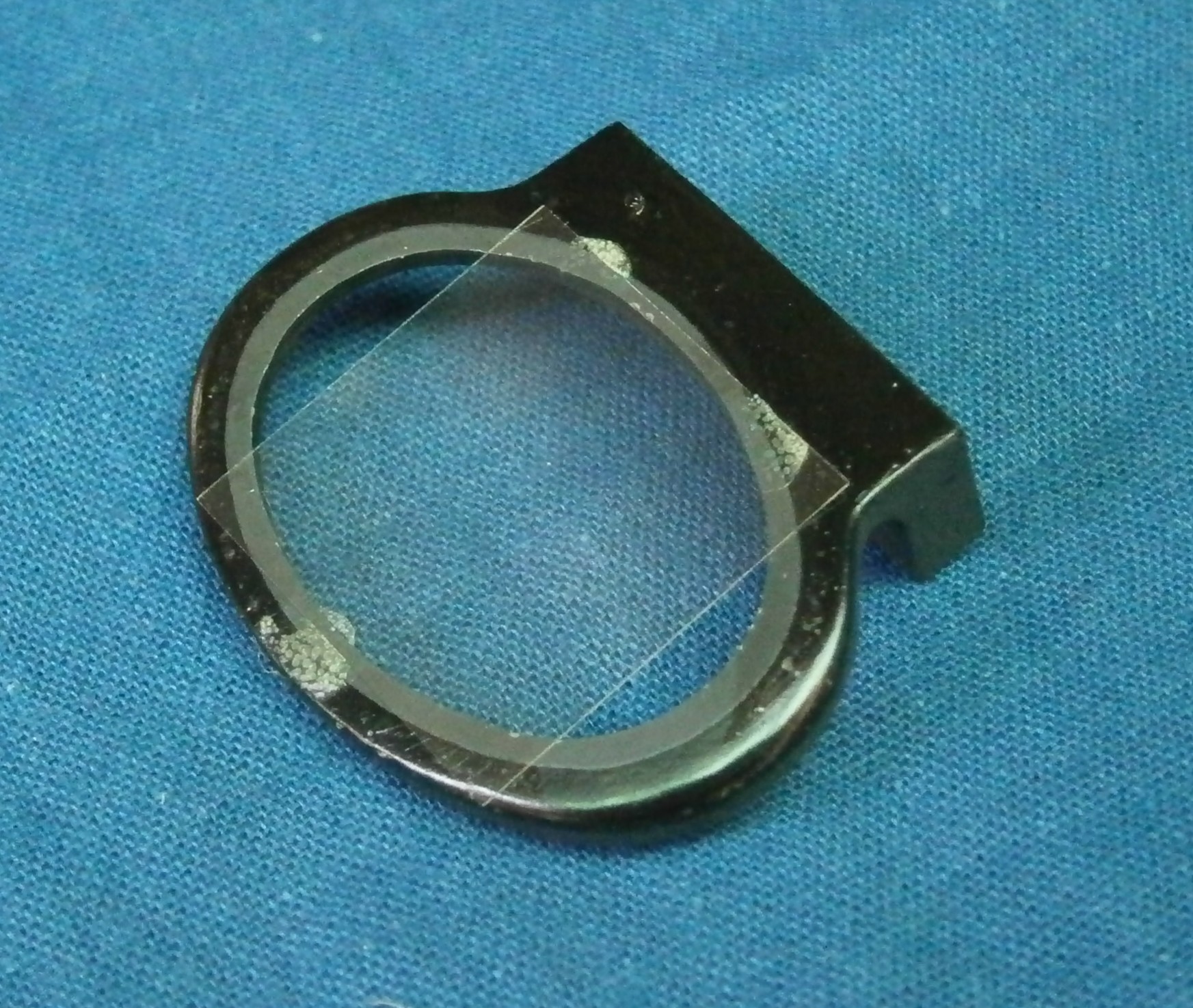
The daylight window and night lighting mirror (Figure 16) were absent. The window was simple to make, but the mirror required more thought and experimentation. The original had an elliptical mirror glued to the end of an aluminium fitting. After a brief trial.I found trimming mirrors to an elliptical shape is not an easy job, so instead I cut off the end of a piece of 32 mm diameter alloy bar at 45 degrees in the band saw and then filed and emery papered the cut surface to a mirror finish, ending with some metal polish. I then turned it down for 60 mm to a snug fit in the end of the sextant and parted off at 63 mm to leave a flange of full diameter (Figure 28). A screw with a head 4 x 3 mm in dimensions fits into a slot in the sextant to ensure correct orientation. It works very well. If there is any tendency for the fitting to slide out in use, the head of the screw can be expanded by opening up the slot with a stout screw driver.
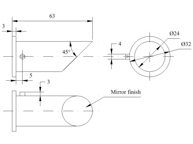
Figure 28 : Night lighting mirror dimensions.
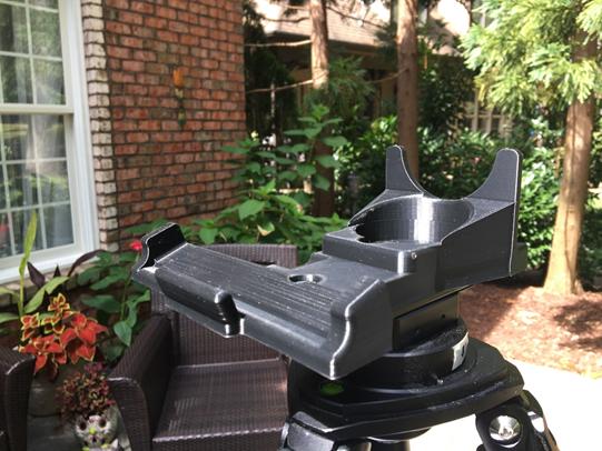
As a final task, I fitted the sextant with a borrowed x 2 1/2 telescope and took observations of the sun near the meridian for a total time of 15 minutes in order to determine the index error of 16 minutes “off the arc”. I made no effort to correct this as the index mirror was very well seated after more than 70 years and I had no wish to break it.
As this web site was started as an encouragement to readers to buy my book “The Nautical Sextant” I hope this post will act as further encouragement to potential readers; and I would also like to draw attention to my book “The Mariner’s Chronometer” More details may be found at www.chronometerbook.com.


You must be logged in to post a comment.