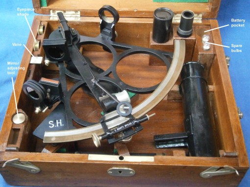
Figure 1: Sextant in its case.
I recently acquired for a relatively modest sum the three-circle vernier sextant shown in Figure 1. Attached at the front corner of the frame is a plate engraved with the letters “S.H.” or “Service Hydrographique (de la Marine)” or French Naval Hydrographical Service, formed in 1886 as successor to the “Dépôt des cartes et plans de la Marine”, founded in 1720. The plate seems to serve no other purpose that I can think of than as an identifier.
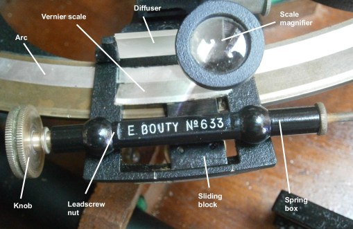
Figure 2: Front of the tangent screw mechanism.
Engraved on the front of the tangent screw mechanism is the name “E. Bouty”. Edmond Bouty (1845 – 1922) was a physicist in the Science Faculty at Paris, but I cannot find that he was an instrument maker, nor is there any other name on the sextant. It may be that his contribution was the design of the scale lighting system, about which more later. It is not even clear that the sextant is of French manufacture, as at the left end of the limb are the letters “D.S.” indicating Deutsche Seewarte, the German Hydrographical Service, but the frame, of about 180 mm radius, differs in detail from that of C Plath’s Dreikreis sextant.
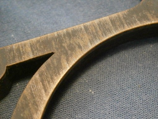
Figure 3: Turning marks on front of frame.
The bronze frame is of no particular interest except that when clearing old and perished paint from the frame during restoration I noticed marks (Figure 3) that showed that it had been faced in a lathe, giving a small clue to the manufacturing process.

Figure 4: Spring box detail.
Returning to the tangent screw mechanism, the spring box is shown exploded in Figure 4. A tongue on the sliding block is trapped between the end of the tangent screw and a long spring mounted on a guide and retained by a nut. The end of the guide can be seen on the right of Figure 2.
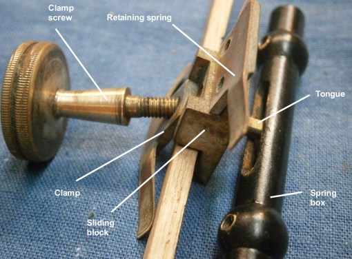
Figure 5: Exploded view of index arm clamp.
The sliding block is retained in its slide in the lower end of the index arm by the retaining spring on the upper right of Figure 5, while the clamp screw and its leaf spring bears on the back of the limb. In use, the clamp is slackened and the index arm moved approximately into position, when the clamp is tightened, thus fixing the sliding block to the limb. Turning the tangent screw thus moves the index arm about the sliding block against the pre-load of the helical spring as a means of fine adjustment. In truth, it is the index arm that slides rather than the sliding block, but as no one else had given it a name, I decided to do so when writing “The Nautical Sextant.” This system of applying pre-load was used in many vernier instruments such as vernier theodolites and gun aiming systems. as well as in several makes of sextant.

Figure 6: Index mirror bracket.
The index mirror is held against a vertical bracket by means of a clip which is tightened against the bracket by means of a screw bearing on the back of the bracket. The mirror is made perpendicular to the arc of the sextant by a system that seems to have been used only by French makers. Two screws attach the radiused feet of the bracket to the upper end of the index arm and the end of a screw held captive in the base of the bracket can then rock the bracket to bring the mirror square to the plane of the arc..
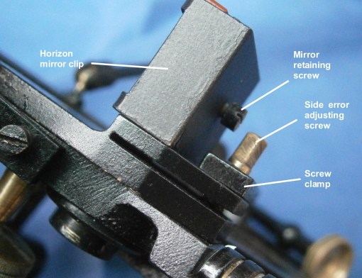
Figure 7: Horizon mirror bracket.
Figure 7 shows a somewhat similar method of adjusting out side error of the horizon mirror, but in this case a deep slot cut nearly through the base of the bracket gives flexibility to the the adjustment by means of another captive screw.

Figure 8: Horizon mirror detail.
The detail shown in Figure 8, as well as making clearer how the mirrors are held against their brackets, shows that the horizon mirror bracket can be adjustably rotated about an axis vertical to the plane of the sextant, in order to adjust out index error. Note that the mirror is fully silvered, which means that the direct view of the horizon does not pass through glass and that the edge of the silvering of the mirror can be given better protection against corrosion. It does however result in a smaller area of overlap of the direct image of the horizon and the reflected image of the observed body when using a Galilean telescope. Enter “Freiberger yacht sextant” in the search box at the top of the page for a discussion of why this is so.

Figure 9: Detail of index error adjustment.
Figure 9 gives more detail on the index error adjustment. There is a boss as an axis on the underside of the horizon mirror bracket that passes through the frame and is held by a retaining screw. A further boss passes through a clearance hole in the frame and has an internal thread tapped in it as a nut. The index error adjusting screw, held captive in the frame by a screw and clamp, engages with the “nut”, so that when the adjusting screw is turned, the whole mirror bracket rotates. When adjustment is complete, the bracket is locked in place by a clamp screw..
This is a rather complex means of adjustment of the horizon mirror, which had long been achieved much more simply by means of a pair of screws bearing against the back of the mirror, while lugs on the mirror clamp provided spring loading. Elegant though it may have seemed to its (?) French inventor, it is unnecessarily complex., though perhaps no more complex than the solution adopted by Brandis and its US successors.

Figure 10: Interior of battery handle.
This sextant represents perhaps one of the earliest ones to light the scale in poor light. Scale lighting had to wait for the development of suitable dry batteries in the 1890s and of miniature flashlight bulbs with robust tungsten filaments in about 1904.
Figure 9 shows the interior of the Bakelite handle which accepts a 3 volt 2R10 battery. A screw at the lower end holds the negative pole of the battery firmly in electrical contact with the frame of the sextant and at the upper end a spring loaded switch plunger makes contact with the positive pole. The top end of the lid is bevelled and the lid itself is slightly bowed, so that when rotated closed it remains in place.

Figure 11: Wire from handle to foot.
A wire passes from the body of the switch to the foot (Figure 11), inside which is a spring loaded brass plunger (Figure 12).

Figure 12: Inside of foot.
The index arm journal is hollow and a wire passes up its centre to an insulated contact on the end, to make electrical contact with the contact inside the foot (Figure 13).

Figure 13: Insulated index arm contact.
The other end of the insulated wire passes down the index arm in a machined groove to a clip held on an insulator block (Figure 14).

Figure 14: Lighting bulb holder.
The clip makes contact with the outside of the bulb holder and thence to the central contact on the bulb. The outside of the holder is insulated from the brass interior, which is threaded for the bulb. The brass interior fits snugly in the cylindrical shade which is attached to the index arm and hence the frame, thus completing the electrical circuit. Most subsequent makers contented themselves with a simple loop of insulated wire to conduct electricity to the bulb, but this more complex and no doubt more expensive system has the merit of not flexing any wire. Like most complex systems, however, there is more to go wrong.

Figure 15: Rising piece.
The telescope rising piece (Figure 15) is simpler than that of many of its early 20th century competitors and it has a rectangular mortice machined in its face to engage closely with a tenon on the telescope bracket, so that it can be slid up or down to vary the amount of light from the horizon entering the telescope. Collimation is standard, by means of a tilting telescope ring held in place by two screws.

Figure 16: Shades mounting.
The shades make none of the usual provisions to prevent movement of one being transmitted to its neighbours. Resistance to rotation is given by means of a Belleville washer, a conical washer with the characteristics of a short, stiff spring. Since these date from about 1870, they add no clues to the age of this sextant.
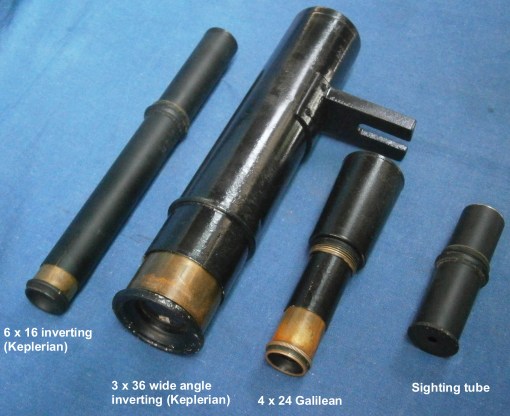
Figure 17: Telescope kit.
The kit of telescopes shown in Figure 16 is for the most part standard, with a 4 x 24 mm Galilean “star” telescope for general use and a 6 x 16mm Keplerian “inverting” telescope. By the twentieth century, this latter probably received little use except for artificial horizon sights to rate chronometers in out-of-the-way places of known longitude. The large 3 x 36mm Keplerian telescope is of interest as it has a wide angle eyepiece with an eye lens of 25 mm aperture. This gives an image nearly as bright as the 4 x 24mm telescope (the extra lens in the eyepiece causes some loss of light) and with a field of view about four to five times wider.
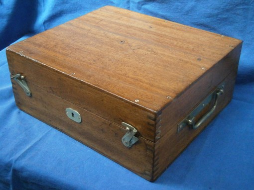
Figure 17: Case exterior.
The mahogany case was much battered and stained, and with several shrinkage cracks, so it was gratifying to be able to restore it to the state shown in Figure 17. It looks decidedly English and placing the handle on the side follows Henry Hughes and Son’s practice, but neither the sextant frame nor the mirror mountings are consistent with this.
If you enjoyed reading about this sextant, you may also enjoy reading my “The Mariner’s Chronometer“, also available via Amazon.com.

Most interesting as usual. Thank you Bill.