A Box Sextant

7 01 2010

All figures may enlarged by clicking on them. Use the back arrow to return to the text.

For a sextant enthusiast, to own a box sextant after handling  full sized instruments gives a lot of pleasure. These dainty and ingenious little instruments, measuring only 75 mm in diameter, can be slipped into a pocket, but be quickly brought out to make a reading with a precision of around an arc-minute. They are equipped with shades that allow sun and moon observations and some models come with a small telescope. They are especially handy for taking horizontal angles on land.

Unfortunately, there are many so-called reproductions on the market, and it may not be easy for the inexperienced to distinguish them from the genuine article. One should look for fine, usually straight  knurling on the adjusting knobs, crisp edges to the index arm and magnifier arm, sharp corners on the bracket that holds the latter, smooth, ground edges to the mirrors and sweet operation of the various adjustments. A bright sky should just be visible through the darkest shade (usually red) and should not be visible at all when used in combination with the second shade (usually blue). The two together should allow comfortable viewing of the full sun.

The scale is usually divided on silver, each degree being divided into halves, with a vernier reading to one minute. The arc radius is about 46 mm. Look for crisp regular engraving of the numerals (Figure 1) rather than the uneven, stamped numbering with rounded edges often seen in  reproductions. The numbering on the vernier usually omits the fives, and a scale with crowded numerals reading 5, 10, 15 etc is quite likely to be a fake. The scale is read from the centre of the index arm, the opposite of a nautical sextant, which is read towards the centre.

Scales 001

Figure 1: Scales of genuine antique.

A maker’s name  may be of little help. There must be thousands of so-called “Stanley” and “Kelvin-Hughes” instruments around, the latter usually dated 1918, nearly thirty years before  the real company came into being. Stanley was a highly respected firm of instrument makers and suppliers, founded in 1853 and trading well into the second half of the twentieth century. Older instruments are engraved “Stanley, London” in beautiful copperplate, though they were probably made (and later labelled) by Heath and Co, with whom Stanley eventually merged in 1926. There are box sextants bearing the name of Elliott Brothers and many other nineteenth century instrument makers and most of these are genuine, but it is important to look at the general workmanship as well as the name. Stanley is the name that has been most abused.

The second photo shows a genuine box sextant by Stanley, alonside its big brother from the same period, a vernier sextant of eight inches radius by Crichton of London, dated to about 1850. The lid unscrews to expose the controls, and is screwed on to the base to act as a handle in use.


The next photo shows the underside of the browned bronze base of the instrument. The nib is used to slide the cover aside. This opens the slot through which shades emerge when not in use, as will be seen in a later picture.

Figure 3: Base.

The general view below shows some of the main features. Rotating the control knob moves the index arm and the vernier over the scale while rotating the index mirror. Note the fine knurling and the crisp edges of the pin holes in the central screw. The magnifierarm, its bracket and the index arm also have crisp edges and the screw slots are narrow, the screw heads polished. Sliding the nib brings the peephole into position and a knurled screw is provided above the peephole to attach the telescope when it formed part of the kit (in some makes, the telescope screwed into the hole). Next to this screw is the mirror-adjusting tool, which screws into place. The levers for bringing the shades into and out of position are to the bottom left of the photo. When they are not in position, they project through the slot described in the preceding paragraph. At the top end of the scale can be seen the two square-headed screws which are used to adjust out side error.

The next photograph shows many of these features from a different viewpoint, that also shows the window opposite the peephole and the head of the screw used to adjust for index error.

For those of you who dare not take their instruments apart, in the next picture I have done it for you, by removing three screws from the periphery of the base plate. The shades are raised out of the way. In use, the head of a limit screw ensures their correct position. The index mirror, its bracket and keeper are mounted on a bearing and are rotated by the toothed sector or rack by means of the control pinion, the business end of the control knob. The horizon mirror sits on a base that can be rocked by means of two spring loaded screws to remove side error and the sub-base below it can be rotated by a further spring loaded screw to remove index error.

The next picture shows another view of the interior to show more details of the horizon mirror arrangement.

Thanks to the kindness of Bill Whiteley, I am now (October 2013) able to add a few sentences about the origins of the box sextant.

A memoir of a meeting appeared in The New Monthly Magazine, Vol 24  1828, of “…the late James Allan mathematical instrument maker in London, who died in the year 1821, compiled by the late Rev. Thomas Macfarlane, minister of Edinkillie, with an introductory letter by Sir Thomas Dick Lauder, Bart. Mr Allan was a native of the parish of Edinkillie, who procured to himself a considerable portion of fame by the discovery of several simple, but most accurate methods of graduating mathematical instruments. The pocket sextant, which gained him the prize and encouragement of the Society of Arts of London, was exhibited on the table of the institution at this meeting. It now belongs to Sir Thomas Dick Lauder.”

 A box sextant presented by the 4th Duke of Gordon to his son in 1813, signed by Allan, is now in the Royal Engineers Museum. This gives us a date before which the instruments were being made.
 
In Nov 1800 James Allan is a shopman (?foreman) lately in the employ of the famous Jessie Ramsden receiving a legacy from Mr Ramsden of twenty pounds. It seems that Allan remained at the Piccadilly workshop, (which had been inherited by Matthew Berge from  Jessie Ramsden,) and was in a position to operate independently. In Nov 1809 he presented to the Royal Society of Arts an improvement on the dividing machine created in 1775 by his former employer Jessie Ramsden. Meantime Berge had amongst other matters, been actively miniaturising the moderately short-lived bridge sextant an instrument which in all probability involved the attention of James Allan.
 There currently exists no firm date for Allan’s creation of his box sextant, However we might assume it to be around the time of his improvements to the dividing machine.
I hope to be able to add a little more about the origins of the box sextant when Bill has had a chance to trawl through the Proceedings of the Royal Society of Arts in the British Library.
12 November 2016: Richard Paselk , Professor emeritus at Humbolt University has kindly just send me this link describing some more of the history of the box sextant: http://www2.humboldt.edu/scimus/AvH_HSU_Centenial%20Exhibit/Box_Sextant/BoxSextant.htm 

Finally, this picture, showing the instrument in use, gives another impression of its size.

If you enjoyed reading this post or found it helpful, do let me know and if you have a “doubtful instrument” I will be happy to view a photo and advise.


A French sextant restoration

25 07 2022

During a lock-down period for Covid 19 in 2021, a large box arrived from a collector in Australia. In it were four antique sextants and a circle which Dave wished me to restore for him and over the intervening months I did just that. A few weeks ago, when New Zealand opened its gates again to overseas visitors, he came to visit his mother, and also made the trip up to the Far North to collect his instruments. During his visit, he was able to look over my few late eighteenth and early nineteenth sextants, and before he left he entrusted me with another sextant and a small box of spare parts, in the hope that I could restore it for display rather than actual use. Figure 1 shows the front or left-hand side of the instrument as received except for the index mirror bracket, which I had cleaned and painted before I had thought about photographing it. I had also removed heavy tarnishing from the scales by dint of patient rubbing with ammonia solution.

Figure 1: Front as found

Missing is any form of sighting device, the index mirror bracket, all the horizon shades, the tangent screw assembly and the shade screen for the vernier scale. A thumb screw half way down the index arm marks where a magnifier arm for reading the scales was no doubt placed. Figure 2 shows the rear or right-hand side as found.

Figure 2: Rear as found

It is somewhat unusual to find a silver-in-brass arc married to a wooden frame, in this case of heart ebony, a strong, dense and stable African hardwood. More usually, wooden framed sextants have ivory arcs glued in a rebate on the front of the limb, while early metal-framed sextants commonly had ivory arcs inlaid. Figure 3 shows one of the nine rivets that attach the arc to the frame and the maker’s name. I have not been able to find any details of Védy of Paris or indeed, whether he was a maker or merely a retailer. The fact that the instrument is numbered suggests the former. Perhaps some reader can tell me more?

The dividing of the scale is of high quality and it is known that Bochard de Saron acquired Jesse Ramsden’s first dividing engine in 1775 and made it available to French artisans until he literally lost his head in April, 1794, during the French Revolution. The state then continued to make it available to instrument makers, including the leading maker, Etienne Lenoir.

Figure 3: Main scale and name.

The mirror adjustments are complex and archaic at a time when most sextants of English manufacture had adopted the simpler method described by Peter Dolland in 1772 in a letter to the Astronomer Royal, Nevil Maskelyne, and published in Phil. Trans. 1772 62, 96 – 98. It was also described in Patent no. 1017 of 22 May 1772. “I have contrived the frame , so that the glass lies on three points, and the part that presses against the front of the glass has also three points exactly opposite to the points between which the glass is placed. This contrivance may be of some use; but the principal improvements are in the methods of adjusting the glasses,...” The method not only removes stresses in the mirror but also allow for simple adjusting of perpendicularity of the index mirror and removal of side and index error at the horizon mirror.

Figure 4 shows the means of adjusting out side error. The horizon mirror is held against a vertical bracket on top of a round base by means of a clip and two screws. The base is hinged on to a rotating base the shaft of which extends through the frame to a means of adjustment to be described below. An adjusting screw operates against a spring that surrounds it, allowing the base to be tilted and the mirror made parallel to the index mirror.

Figure 4: Means of correcting side error.

Figure 5 shows the end of the shaft of the rotating base. It is connected via a square on the end of the shaft to a sector that has a half-nut on its end which engages with a worm inside a fabricated brass box. The sector is retained on the shaft by a screw with a large head(not shown). The worm box is attached to the frame by means of two screws which engage with two threaded brass bushes let into the frame. The sector can be locked in place by means of a clamp screw. Rotating the squared end of the worm shaft in turn rotates the rotating base and allows fine adjustment of the index error. Figure 6 shows the assembly exploded.

Figure 5: Means of correcting index error.
Figure 6: Index error adjustment exploded.

In the box of possible spare parts was a sighting tube. Happily, the thread on its body was of a larger outside diameter and of a different pitch to the internal diameter of the existing telescope rising piece, so I was able to turn it down and cut a new matching internal thread. I was able to ascertain the pitch of the latter by pressing a piece of Plasticene into the thread, removing it and then using an engineering microscope to measure the impressed thread.

Figure 7: Telescope mounting

Figure 7 shows the telescope mounting. Avid readers of this blog will have noticed the similarity of the mounting to that shown in Figure 1 of my post of October, 2021, on a reflecting circle. This does not necessarily mean that the two instruments were contemporary, but rather that apprentices would copy masters, sometimes over several generations, or specialist makers of small parts would supply to “makers”, who were assemblers and finishers, rather like modern automobile manufacturers.

Figure 8 shows the mounting exploded. A large knurled nut holds a bush securely in the frame and the triangular stem of the rising piece slides in a triangular hole in the bush. A screw is held captive in the bush by means of a knurled thimble which has a square hole in it to match the square on the end of the screw. A countersunk screw(not shown) passes through the thimble into the end of the adjusting screw and tightening it secures the adjusting screw in the bush, allowing free rotation without up and down movement.

Figure 8: Telescope mounting exploded.
Figure 9: Tangent screw.

Reference to Figures 1 and 2 shows that the tangent screw with its nut and bearing were entirely missing, the sliding block was present and a mangled leaf spring remained. With the parts available, I was not able accurately to reproduce what was present before, but Figure 8 shows a closely similar appearance, the main difference being that the bearing was secured by means of a screw passing from the front of the index arm into its base. The original bearing was probably spherical and held in a spherical seat.

When the lock screw is tightened, the sliding block is locked to the limb and when the tangent screw is rotated the index arm slides over the block. When the lock is loosened, the index arm can be slid rapidly along the limb, while the leaf spring holds the arm in contact with the frame. The original spring and the little block that held it were too badly mangled to use and I had to make new ones. I resisted the temptation to use a piece of clock spring or a scrap of beryllium copper, and instead hammered a strip of brass to work harden it and make it springy as a contemporary artisan would have done. The resulting distortions had to be corrected by filing.

In the upper left of Figure 7 can be seen the way the index mirror is brought perpendicular to the plane of the arc. An adjusting screw with a square head is held captive in a tongue projecting from the index mirror bracket by means of a bar and two screws. There are two screws through feet securing the front of the bracket and their soles are slightly rounded to allow rocking as the adjusting screw is rotated in a threaded bush let into the top of the index arm. Peter Dollands invention, mentioned above, made these little complexities redundant. A mirror clip from the box of spare parts was easily modified with a file to fit the bracket.

There were three rather battered horizon shades in the box of parts and it was the work of a few minutes to make a shouldered screw and three washers to fit them into the existing bracket. I domed a further thin washer by placing it on the end grain of a scrap of wood, sitting a ball bearing in the hole and striking it hard with a hammer. This gave me a thin and stiff spring to adjust the friction when the screw was tightened. This type of spring washer is now known as a Belleville washer, patented in 1867 by Julien Belleville of Dunkirk. Fairly obviously, the principle was well known before that. A lock nut at the end of the screw then completed the assembly.

Figure 10: Horizon shades.

The index arm bearing followed the pattern shown in Figures 25 and 26 of my post for 11 March 2012 and it required only cleaning and greasing.

I used black laquer on brass surfaces, leaving screw heads bright as seems to have been the custom, and used black shoe polish to brighten the frame to complete the restoration.

Figure 10: Completed front view.
Figure 11: Completed rear view

The finished restoration is shown in Figures 10 and 11.

Postscript Murray Peake has kindly provided me with some details of the maker, Louis Félix Védy, 1811 – 1875. He was active in the middle of the nineteenth century and was a principle supplier to the Dépot de la Marine. He was made a Chevalier de la Legion d’Honneur in 1851. His apprentice master was Antoine-Francois Jecker, 1765 – 1834, who worked for six years under Jesse Ramsden.


A Small Ramsden Sextant

14 10 2021

On page 64 of Peter Iflands Taking the Stars is a figure showing a small sextant bearing Jesse Ramsden’s name. According to Ifland, this was one of the last sextants made by Ramsden, though by the time of his death he had many workmen and it is unlikely that he made the instrument personally. Part of a batch of instruments sent to me by a friend in Australia for restoration was an identical instrument named W Harris 47 Holborn London. Harris was active from 1816 to 1839, though he almost certainly did not make the sextant bearing his name. It was common practice for retailers to put their own names on sextants, clock, chronometers and the like that had been made by others. Figure 1 shows the sextant in the condition that it reached me and Figure 2 shows the naming.

Figure 1: Sextant as received
Figure 2: Name.

Apart from the obvious dirt and perished shellac, the scale magnifier, horizon mirror clip and mirror, handle and sundry screws were broken or missing, while the tangent screw adjustment was seized. I followed my usual practice of reducing the instrument to its individual parts for a thorough clean in soapy ammonia solution followed by removal of all the decayed shellac and broken screws.

My friend had sent me a box of optical parts which included an Ramsden-type magnifier from a small theodolite complete with threaded barrel, so that my task was to saw out the arm from 3mm brass sheet, file it to final shape and cut an interior thread in the lathe to accept the barrel. Unfortunately, the square on top of the pillar had corroded away, but as the instrument was only to be displayed in future, I simply attached the arm with a screw (Figure 3).

Figure 3: New magnifier arm.

I made the missing horizon mirror clip by folding and soldering thin brass sheet, making and soldering in place a threaded boss for the retaining screw. The clip is visible in several of the figures that follow, including Figure 4 which shows the restoration largely complete.

Figure 4: Restoration nearly complete.

The index arm bearing is the conventional tapered brass journal in a bronze bearing that Ramsden made much use of in all his instruments and it is possible that he originated the practice. The bearing had become detached from the frame and was much battered, so I had to turn down the outside from its rough cast and bruised state. As there were no screws and it was impossible to determine the pitch of the old ones, as there was no standardisation of screws until the mid-1800s, I had to re-tap the holes to a BA standard and make new screws to fit (Figure 5). A threaded cap covers the end of the bearing and also acts as a leg.

Figure 5: Rear view of restored instrument.

The most striking feature of this little instrument is that the scales are both bevelled so both lie in the same plane, making for easy reading as both have the same contrast. Less obvious is that the scales are read from the centre of the instrument, rather than from the edge of the limb (Figure 6).

Figure 6: Scales and Tangent screw details

The arrangement for the tangent screw is rather unusual The screw is held captive in a bearing which is attached to the clamp, the underside of which may be seen in Figure 5 above. A curved tongue extends from the clamp and fits closely in a groove machined in the lower end of the index arm. The base of the nut retains it in place. The nut is attached to the index arm so that when the clamp is operated and the screw turns, the index arm is rotated and slides smoothly along the stationary tongue.

No provision is made to adjust perpendicularity of the index mirror, rather, it was made correct in the first place, a practice followed by only a minority of late nineteenth and twentieth century sextants. However, there is provision to make the horizon mirror parallel to the index mirror to adjust out side error, and to rotate the horizon mirror to adjust out index error (Figure 7).

Figure 7: Horizon mirror adjustments.

There was a wide variety of methods to adjust the horizon mirror, lasting even into the 1940’s with the perverse methods used in the US Navy’s Mark II sextant (described in my post of 30 November 2010). However, Peter Dolland took out a patent number 1017 in May 1772 for “Adjusting and improving the glasses of Hadley’s quadrants and sextant…”. In a letter to Neville Maskelyne (Phil.Trans. 1772 62, 95-98) he described the method which has been used for the large majority of sextants for most of the last century and a half, that of three screws bearing on the back of the mirror and opposed by three springs at the front.

Nevertheless in the late eighteenth and most of the nineteenth century, sextants used a variety of complex and ingenious ways to accomplish the same thing. Figure 7 above shows the approach taken with this little sextant. The horizon mirror is held against three pips on a bracket by a clip and a screw bearing on the back of the bracket. The bracket is mounted on a base which has two pips on its underside more or less at right angles to the telescope axis and the base is rocked with these pips as an axis by means of two screws, the rear one of which pulls from below by means of a knurled screw while the other one pulls from above by means of a slotted cheese head screw. It seems that there may have at one stage been a spring involved that allowed just the use of the front screw, but I was unable from the remains to work out how this was arranged.

This tilting base is attached by the screws to a rotating base and a slot is machined in the face of the frame to accommodate a tongue that ends beneath a rectangular hole in the rear of the frame. A cover extends from the rotating base to cover the roof of the slot (Figure 7) while another cover is provided to cover the hole in the rear (Figure 8). The tongue can be moved back and forth against a stout helical spring by means of a screw that passes through a threaded boss, thus rotating the mirror to adjust out index error. The foot of the boss is retained in the frame by two retaining pins.

Figure 8: Index error adjustment detail.

All that remains is to note that the arrangement of the four index shades is conventional, while the three horizon shades are neatly fitted in as shown in Figure 7 above. The shades fit over a pillar and are held in place by a squared washer and a cheese-headed screw. The squared washer prevent rotation forces from being transmitted from the shades to the screw, so that latter can be used to adjust the friction without risk of it undoing.

I have two more sextants to describe from the current batch of restorations as family and other commitments decide and hope that you have enjoyed your reading so far. If there is any specific topic you would like me to cover, please let me know at nzengineernz@gmail.com (I have no formal engineering qualifications, but during my clock-building years, someone called me a time engineer…).


Mending a 1975 SNO-T sextant.

28 10 2020

A little while ago I bought a SNO-T sextant on a local auction site, not because I did not have one (I have two), but because the price was too attractive to miss. I found there were two major and one minor problems with the instrument: one hinge had torn from the the case, one shade was a “foreigner” taken from an SNO-M sextant and the star or Galilean telescope was out of alignment. Some may not think the damage to the case to be important, but a sextant is an instrument of precision and if it is not contained safely in its case it may suffer unnoticed damage. Figure 1 shows that a cure could not be effected with filler or “builder’s bog”. I had to saw and chisel away the damage down to fresh wood and glue in a piece of close grained wood .

Figure 1: Case damage.

Figure 2 shows the result, with screw holes marked out and pilot holes for screws drilled.

Figure 2: Wood inserted

As a later photograph will show, the designs of the shades for the SNO-T and the SNO-M are very different, so I elected to make a new bracket and use the glass from the SNO-M. I began by marking out a piece of aluminium alloy plate and boring a hole to make a seat for the glass.. Rather than swaging the glass into place, I planned to use modern two-part epoxy glue.

Figure 3: Boring the shade bracket blank.

The next step was to saw the outline of the blank to shape with a piercing saw (Figure 4) and finishing by filing.

Figure 4: Sawing the bored blank to shape.

Figure 5 shows how “cheaters” are used to guide the file when making tight curves in soft metals like aluminium and brass. They are simply hardened cylinders held in place with a nut and bolt and when a gently used file begins to skate over them, the soft metal has been guided into shape.

Figure 5: “Cheating” a curve.

All that remained was to ease the glass into place with a tiny smear of glue to hold it there and paint it to match the rest of the sextant. “Hammerite” hammered grey paint gives a close match. Figure 6 shows the completed shade.

Figure 6: Completed shade on left.

The “star” telescopes of most sextants are not adjustable for collimation. The word appears to have come from the mis-copied Latin word “collineare”, to direct something in a straight line according to the Oxford Latin Dictionary. In the context of sextants, it means to direct the optical axis of the telescope parallel to the plane of the arc. Except at high altitudes, small errors are of little importance in ordinary navigation. For example at a reading of 60 degrees, a 45 minute tilt of the telescope results in an error of about 20 seconds, an amount which would normally be swamped by other errors. However, in the days of lunar distance observations and checking chronometers by celestial observations, such an error would be significant, and the higher powered inverting or Keplerian telescopes were normally provided with a means of collimation.

The easiest way to check collimation is to check that the face of the objective lens cell is at right angles to the plane of the frame of the sextant, a shown in Figure 7, where there is an obvious wedge of light showing,

Figure 7: Mis-collimated telescope

The rising piece of the SNO-T telescope is a casting that is integral with the body of the telescope and one would be ill-advised to attempted to correct the error by bending it, as aluminium castings have an unfortunate tendency to give no warning that they are about to break. Instead, it is simpler and safer to slowly and carefully file the underside of the telescope bracket, where there is usually plenty of metal, and this is what I did. Figure 8 shows that the error has been corrected.

Figure 8: Telescope collimated.

I have dealt with the rest of the overhaul in my manual on the construction, repair and maintenance of the SNO-T Sextant, which is still available for purchase (see post for 22 November 2008 for details). Figure 9 shows the instrument in its repaired case. The original colour of the case was light grey, and as it had become battered during its life since 1975, and I had some very tough gloss blue paint left over from another job, I used it on the outside, while touching up the lemon yellow of the interior and renewing the felts. The match of the yellow is not perfect, but is much better than nothing.

Figure 9: Overhauled sextant in its up-graded case.


A French Hydrographic Sextant

13 01 2019

2 a case inside

Figure 1: Sextant in its case.

I recently acquired for a relatively modest sum the three-circle vernier sextant shown in Figure 1. Attached at the front corner of the frame is a plate engraved with the letters “S.H.” or “Service Hydrographique (de la Marine)” or French Naval Hydrographical Service, formed in 1886 as successor to the “Dépôt des cartes et plans de la Marine”, founded in 1720. The plate seems to serve no other purpose that I can think of  than as an identifier.

3 a e bouty name

Figure 2: Front of the tangent screw mechanism.

Engraved on the front of the tangent screw mechanism is the name “E. Bouty”. Edmond Bouty (1845 – 1922) was a physicist in the Science Faculty at Paris, but I cannot find that he was an instrument maker, nor is there any other name on the sextant. It may be that his contribution was the design of the scale lighting system, about which more later. It is not even clear that the sextant is of  French manufacture, as at the left end of the limb are the letters “D.S.” indicating Deutsche Seewarte, the German Hydrographical Service, but the frame, of about 180 mm radius, differs in detail from that of C Plath’s Dreikreis sextant.

2 b frame turning marks

Figure 3: Turning marks on front of frame.

The bronze frame is of no particular interest except that when clearing old and perished paint from the frame during restoration I noticed marks (Figure 3) that showed that it had been faced in a lathe, giving a small clue to the manufacturing process.

3 c spring nut

Figure 4: Spring box detail.

Returning to the tangent screw mechanism, the spring box is shown exploded in Figure 4. A tongue on the sliding block is trapped between the end of the tangent screw and a long spring mounted on a guide and retained by a nut. The end of the guide can be seen on the right of Figure 2.

3 b clamp

Figure 5: Exploded view of index arm clamp.

The sliding block is retained in its slide in the lower end of the index arm by the retaining spring on the upper right of Figure 5, while the clamp screw and its leaf spring bears on the back of the limb. In use, the clamp is slackened and the index arm moved approximately into position, when the clamp is tightened, thus fixing the sliding block to the limb. Turning the tangent screw thus moves the index arm about the sliding block against the pre-load of the helical spring as a means of fine adjustment. In truth, it is the index arm that slides rather than the sliding block, but as no one else had given it a name, I decided to do so when writing “The Nautical Sextant.” This system of applying pre-load was used in many vernier instruments such as vernier theodolites and gun aiming systems. as well as in several makes of sextant.

4 perp adjust

Figure 6: Index mirror bracket.

The index mirror is held against a vertical bracket by means of a clip which is tightened against the bracket by means of a screw bearing on the back of the bracket. The mirror is made perpendicular to the arc of the sextant by a system that seems  to have been used only by French makers. Two screws attach the radiused feet of the bracket to the upper end of the index arm and the end of a screw held captive in the base of the bracket can then rock the bracket to bring the mirror square to the plane of the arc..

5 side error

Figure 7: Horizon mirror bracket.

Figure 7 shows a somewhat similar method of adjusting out side error of the horizon mirror, but in this case a deep slot cut nearly through the base of the bracket gives flexibility to the the adjustment by means of another captive screw.

7 horizon mirror

Figure 8: Horizon mirror detail.

The detail shown in Figure 8, as well as making clearer how the mirrors are held against their brackets, shows that the horizon mirror bracket can be adjustably rotated about an axis vertical to the plane of the sextant, in order to adjust out index error. Note that the mirror is fully silvered, which means that the direct view of the horizon does not pass through glass and that the edge of the silvering of the mirror can be given better protection against corrosion. It does however result in a smaller area of overlap of the direct image of the horizon and the  reflected  image of the observed body when using a Galilean telescope. Enter “Freiberger yacht sextant” in the search box at the top of the page for a discussion of why this is so.

6 index error

Figure 9: Detail of index error adjustment.

Figure 9 gives more detail on the index error adjustment. There is a boss as an axis on the underside of the horizon mirror bracket that passes through the frame and is held by a retaining screw. A further boss passes through a clearance hole in the frame  and has an internal thread tapped in it as a nut. The index error adjusting screw, held captive in the frame by a screw and clamp, engages with the “nut”, so that when the adjusting screw is turned, the whole mirror bracket rotates. When adjustment is complete, the bracket is locked in place by a  clamp screw..

This is a rather complex means of adjustment of the horizon mirror, which had long been achieved much more simply by means of   a pair of screws bearing against the back of the mirror, while lugs on the mirror clamp provided spring loading. Elegant though it may have seemed to its (?) French inventor, it is unnecessarily complex., though perhaps no more complex than the solution adopted by Brandis and its US successors.

9 battery handle

Figure 10: Interior of battery handle.

This sextant represents perhaps one of the earliest ones to light the scale in poor light. Scale lighting had to wait for the development of suitable dry batteries in the 1890s and of miniature flashlight bulbs with robust tungsten filaments in about 1904.

Figure 9 shows the interior of the Bakelite handle which accepts a 3 volt 2R10 battery.  A screw at the lower end holds the negative pole of the battery firmly in electrical contact with the frame of the sextant and at the upper end a spring loaded switch plunger makes contact with the positive pole. The top end of the lid is bevelled and the lid itself is slightly bowed, so that when rotated closed it remains in place.

10 b handle to bearing

Figure 11: Wire from handle to foot.

A wire passes from the body of the switch to the foot (Figure 11), inside which is a spring loaded brass plunger (Figure 12).

10 a switch to contact

Figure 12: Inside of foot.

The index arm journal is hollow and a wire passes up its centre to an insulated contact on the end, to make electrical contact with the contact inside the foot (Figure 13).

11 a journal contact

Figure 13: Insulated index arm contact.

The other end of the insulated wire passes down the index arm in a machined groove to a clip held on an insulator block (Figure 14).

12 lighting system

Figure 14: Lighting bulb holder.

The clip makes contact with the outside of the bulb holder and thence to the central contact on the bulb. The outside of the holder is insulated from the brass interior, which is threaded for the bulb. The brass interior fits snugly in the cylindrical shade which is attached to the index arm and hence the frame, thus completing the electrical circuit. Most subsequent makers contented themselves with a simple loop of insulated wire to conduct electricity to the bulb, but this more complex and no doubt more expensive system has the merit of not flexing any wire. Like most complex systems, however, there is more to go wrong.

13 rising piece in situ

Figure 15: Rising piece.

The telescope rising piece (Figure 15) is simpler than that of many of its early 20th century competitors and it has a rectangular mortice machined in its face to engage closely with a tenon on the telescope bracket, so that it can be slid up or down to vary the amount of light from the horizon entering the telescope. Collimation is standard, by means of a tilting telescope ring held in place by two screws.

8 index shades

Figure 16: Shades mounting.

The shades make none of the usual provisions to prevent movement of one being transmitted to its neighbours. Resistance to rotation is given by means of a Belleville washer, a conical washer with the characteristics of a short, stiff spring. Since these date from about 1870, they add no clues to the age of this sextant.

15 telescopes

Figure 17: Telescope kit.

The kit of telescopes shown in Figure 16 is for the most part standard, with a 4 x 24 mm Galilean “star” telescope for general use and a 6 x 16mm Keplerian “inverting”  telescope. By the twentieth century, this latter probably received little use except for artificial horizon sights to rate chronometers in out-of-the-way places of known longitude. The large 3 x 36mm Keplerian telescope is of interest as it has a wide angle eyepiece with an eye lens of 25 mm aperture. This gives an image nearly as bright as the 4 x 24mm telescope (the extra lens in the eyepiece causes some loss of light) and with a field of view about four to five times wider.

1 a case exterior

Figure 17: Case exterior.

The mahogany case was much battered and stained, and with several shrinkage cracks, so it was gratifying to be able to restore it to the state shown in Figure 17. It looks decidedly English and placing the handle on the side follows Henry Hughes and Son’s practice, but neither the sextant frame nor the mirror mountings  are consistent with this.

If you enjoyed reading about this sextant, you may also enjoy reading my “The Mariner’s Chronometer“, also available via Amazon.com.


Hughes Marine Bubble Sextant

26 11 2018

This post was preceded by  “An improvised sun compass”, ” C Plath Sun Compass”; “A Fleuriais’ Marine Distance Meter” A Stuart Distance Meter”;“A Russian Naval Dip Meter”; and  “An Improvised Dip Meter”

Jaap Brinkert has kindly provided the following post . With his agreement, I have added an occasional comment in blue.

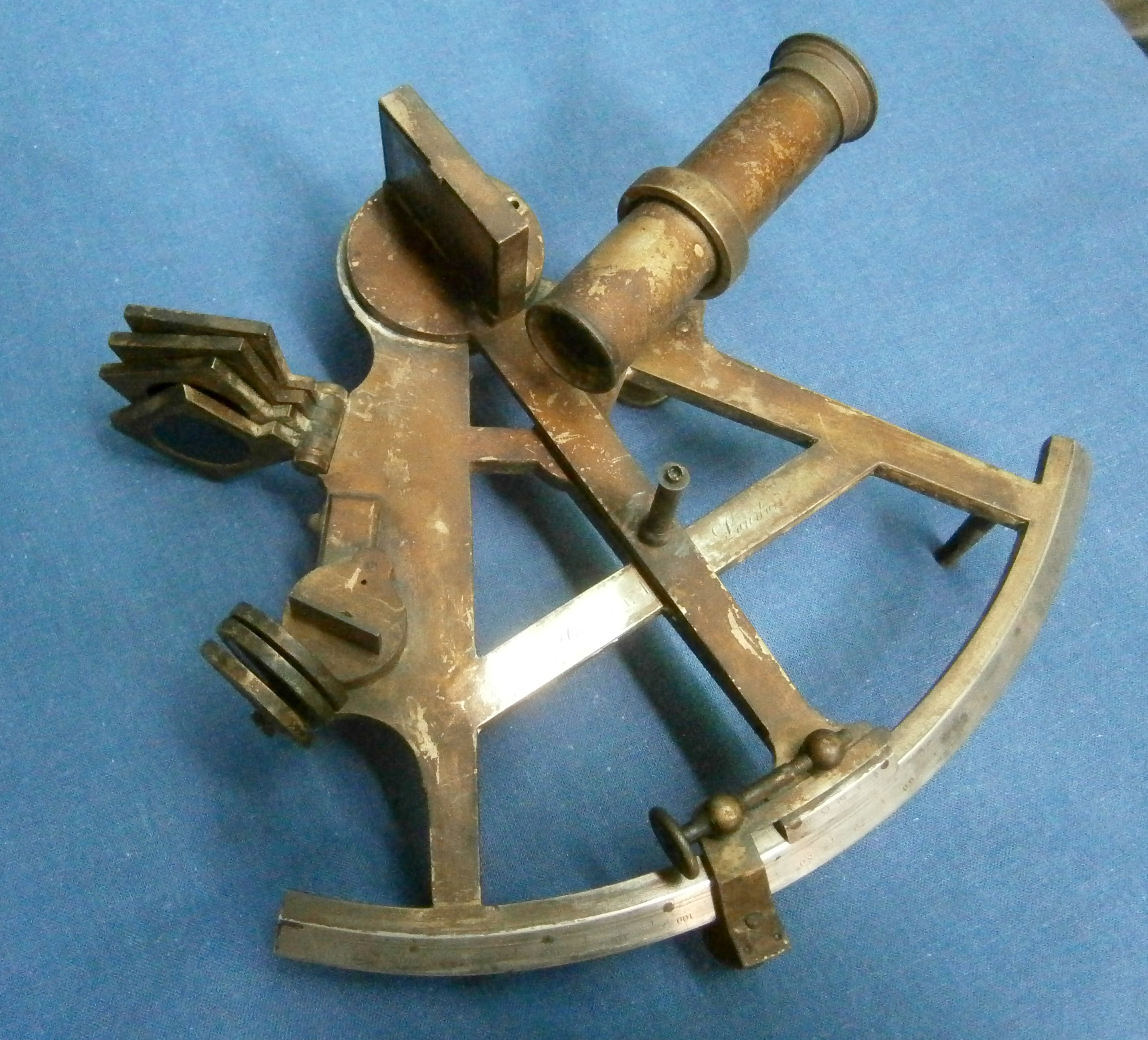
Recently, I won the bidding on a ‘Vintage Marine Sextant’ which I soon discovered to be rather unusual. At first sight, it resembles the Hughes Mk IX bubble sextant as used by the RAF (and others) during WWII (Figure 1 and 2).  However, this sextant is intended for marine use. It appears that the German navy started using bubble sextants on board submarines, so that they could take sights when surfaced at night The Hughes Marine Bubble Sextant (HMBS) was the English answer, developed after tests using the Mk IX on board a submarine. {1} “Highly accurate results” seem to me to have been unlikely. One to three nautical miles would be counted good using a normal  nautical sextant and the natural horizon.

Rear

Figure 1: Rear view of Mk IX A and HMBS sextants

A good general description of the device is given in “Specification of instruments exhibited at the seat of the international hydrographic bureau during the Vth international hydrographic Conference, Monaco, April 1947,” in which exhibit number. 8 of Marine Instruments Ltd, entitled “Marine Super Integrating Sextant” is described as follows. “The instrument consists of a sextant, the mechanism of which is totally enclosed with the usual fixed horizon mirror and adjustable index mirror. The mechanism is arranged to give arbitrary increments of altitude of 10 degrees, -10 to 90. Attached to the main body of the sextant by two screws is the bubble complete with eyepiece through which the observer sees the bubble and the object observed. A single instantaneous observation is made by setting the next lowest whole tens of degrees and then using the slow motion to obtain coincidence between the centre of the bubble and the object, reading the altitudes on the tens of degrees scale and the degrees and minutes scale (instantaneous reading. 

An averaging observation is made by maintaining the coincidence as nearly as possible during the one-minute period of observation between starting the clock drive and the automatic raising of the cut-off shutter, the altitude being read on the tens of degrees scale and the degrees and minutes scales (averaging). 

A second bubble unit is provided, interchangeable with that on the instrument. This unit is exactly the same as the first, except that it carries a 2X Galilean telescopes mounted in the unit itself, which, when sea conditions permit, gives brighter star images than would otherwise be obtained.  

Two dry batteries and two spare lamps are supplied.”

LH side

Figure 2: LHS of Mk IX A and HMBS sextants.

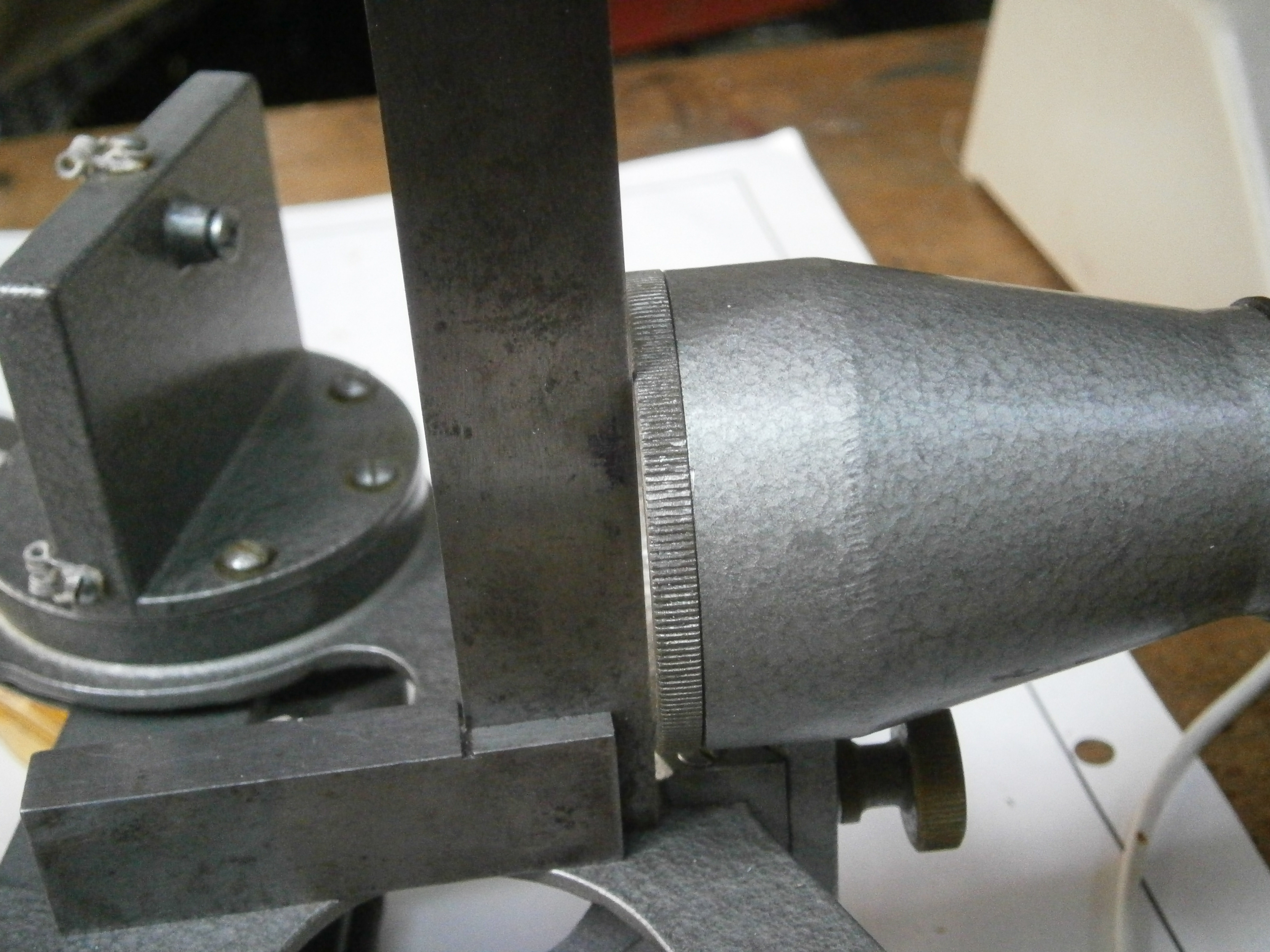
The Marine Bubble sextant has an entirely different mechanism for averaging, which is contained within the main body, where it is protected from salt spray. It is a continuous integrating mechanism, which runs for one minute. The adjustment of the index mirror also sets the transmission ratio between a slender cone, driven at constant speed by a spring mechanism, and a cylinder connected to the totaliser (Figure 3).

Integrator

Figure 3: Integrator mechanism.

This is in effect the reverse of the mechanism used in the German SOLD and Kreisel (gyro) sextants, where the inclination of a roller that bears  on a shaft moving longitudinally, variably rotates the shaft, on the end of which is attached the read-out. Full details may be found in the post for  4 November 2013 . After the one minute run, the average position of the index mirror is read from a dedicated dial, and added to the setting of the index mirror, for instance 70 +4 35′.

The averaging device for the Mark IX A aeronautical sextant sampled one sixtieth of the reading every two seconds for two minutes, in effect integrating the reading over sixty intervals. The potential disadvantage of this is that if the sampling interval happens to coincide with the approximate frequency of rolling of the vessel, large errors may be introduced. The HMBS, like the SOLD and Kreiselsextant, continuously integrates the reading.

 https://www.thejot.net/article-preview/?show_article_preview=85&jot_download_article=85 has a submarine rolling at 2.4 to 3.9 seconds for a closed casing submarine. The implication of this is that it might be best to avoid sampling periods in this range. (Thanks to Murray Peake for this information)

Calibration

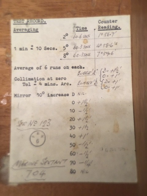
Figure 4: Calibration record.

The calibration record (Figure 4) is interesting as it illustrates the consequence of a difference in timing mechanism between the SOLD and the HMBS. The former contains a “proper” clockwork with balance wheel and escapement. The latter, on the other hand, contains a regulator mechanism which uses centrifugal force and friction (if the regulator turns too fast, it ‘expands’ against a stationary drum, resulting in deceleration). This mechanism needs to be calibrated. The certificate shows  a deviation of up to 1%, depending on the set angle). A small error in counter reading follows automatically. The calibration also shows the separate extra corrections for the two bubble units. Using this sextant requires quite a bit of bookkeeping!

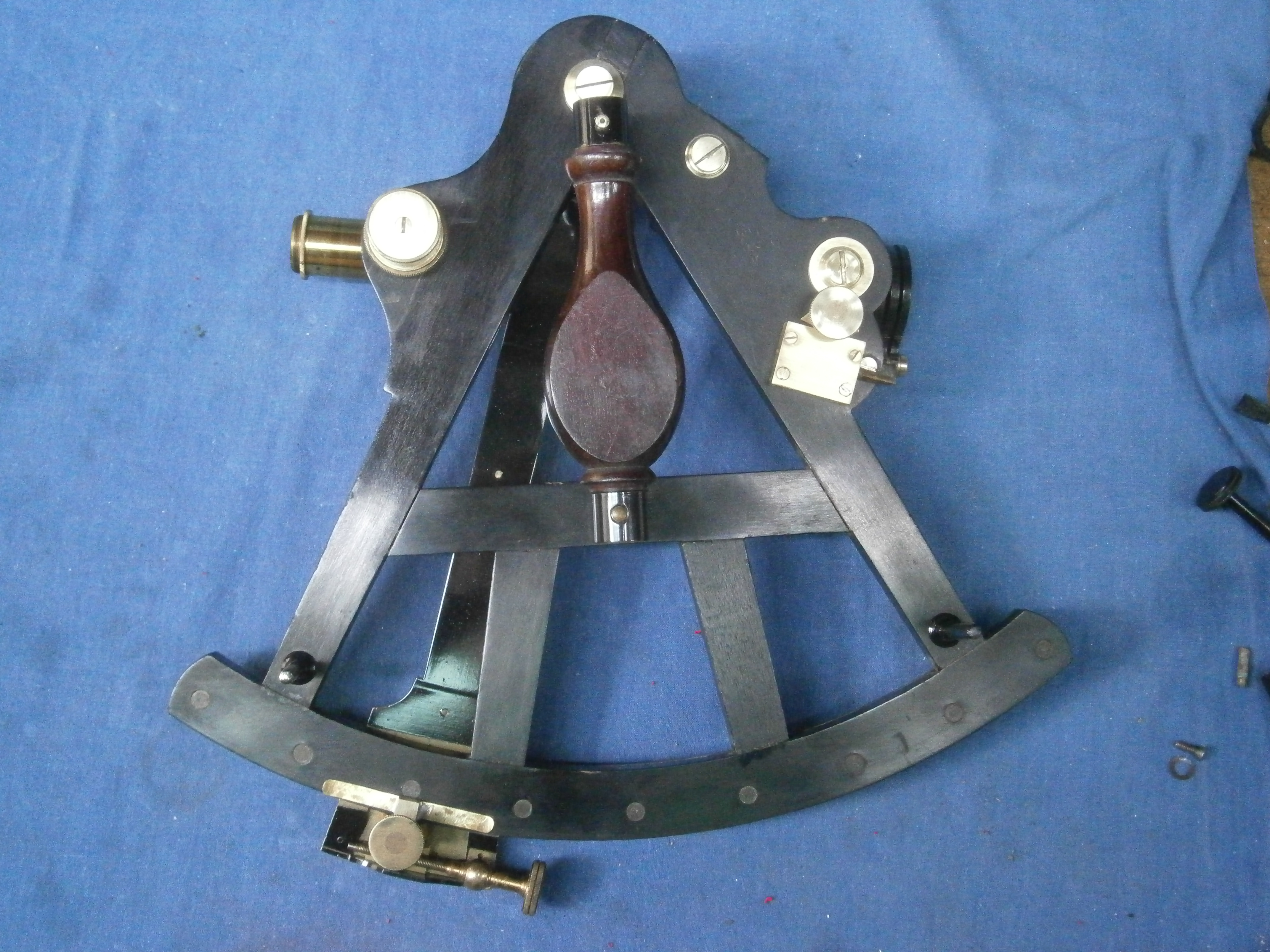
As for a normal sextant, the HMBS has a conventional set up, except for the placing of the shades (Figure 5).

Front labelled

Figure 5: Front view, showing mirrors

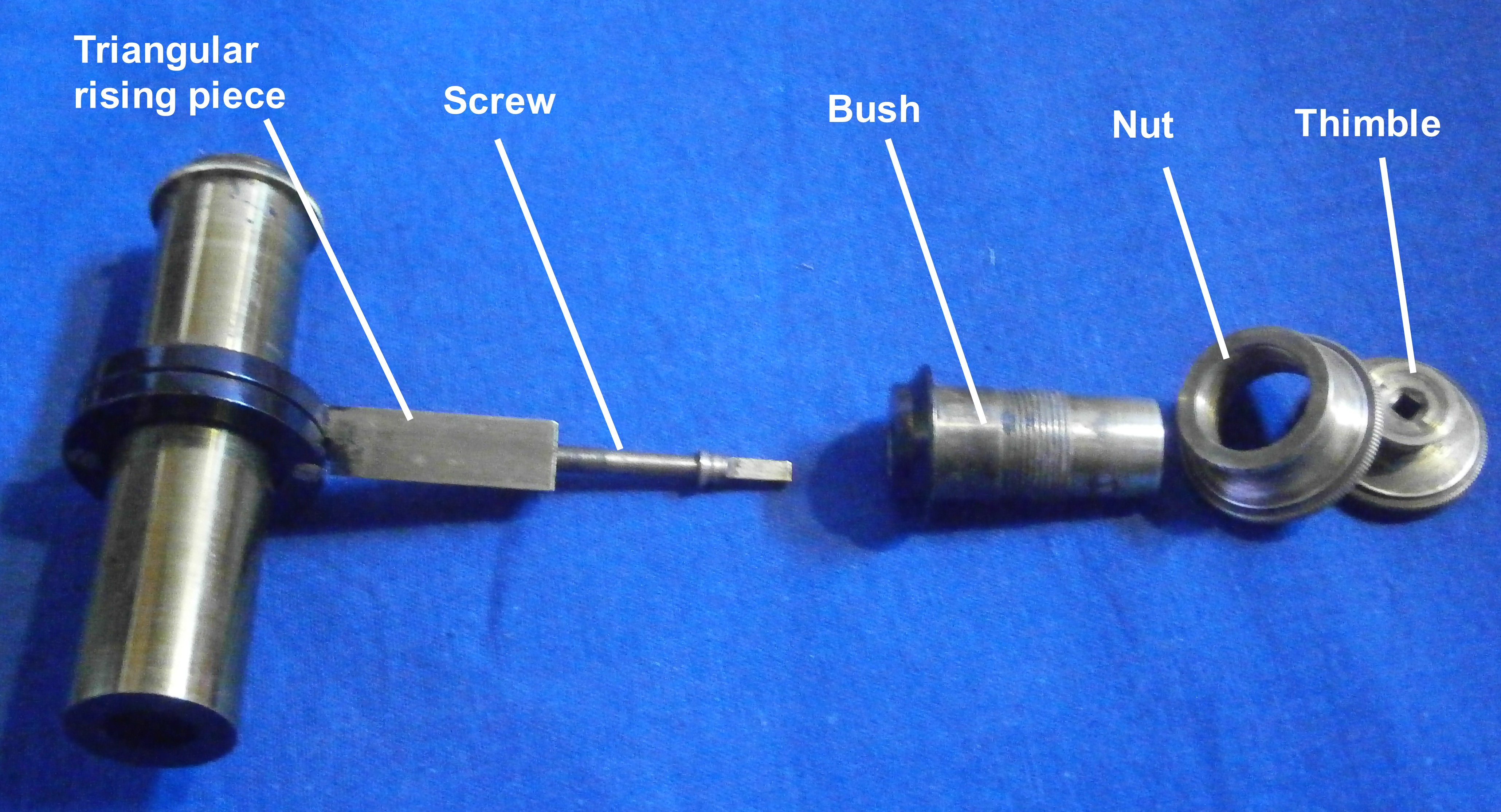
The index mirror is rotated on a shaft which emerges from the main housing, and is operated by a mechanism described below. In operation, this mechanism is similar to that of the Mk IX series. There is a large step setting in tens of degrees (-10 (“D”) to +80 ) and a fine setting ( 0 0′ to 14 50′ in 1.5 turns of the adjusting wheel). The index mirror is quite large: 70 mm by 27 mm. Another difference between the Mk IX and the HMBS is the horizon mirror: it has no ‘5 degree increase’ facility, which also simplifies the read out mechanism for the averager. The horizon mirror of the HMBS is fixed; the whole nearly 15 degree range is set by the mirror fine-setting control. The Mk IX index mirror is the same length but only 24 mm wide. In both sextants, the length of the mirror is required because the axis of rotation of the mirror is quite far behind the mirror in order to accommodate a central helical spring and concentric shaft mounting (Figure 6).

Index mirror 3

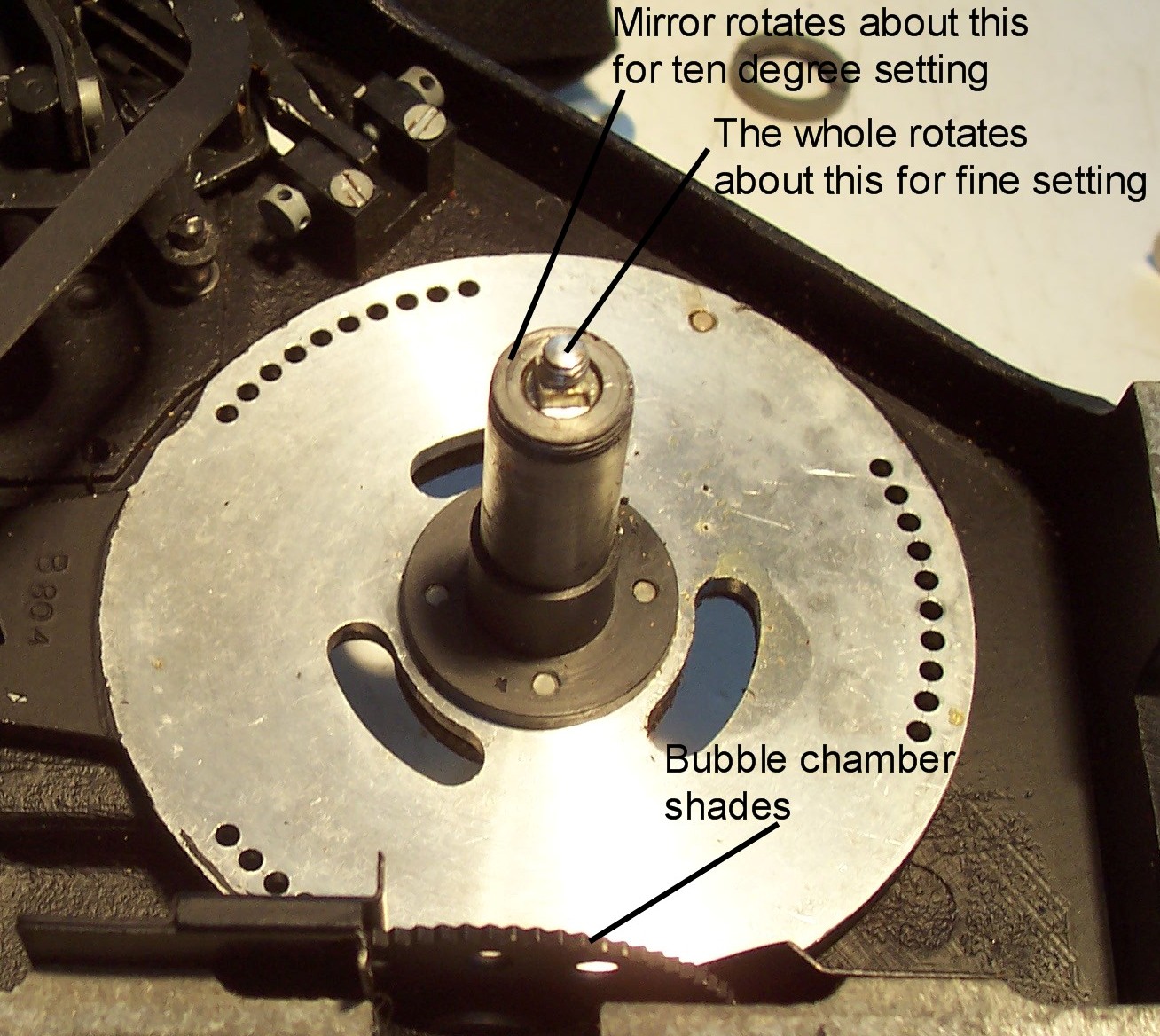
Figure 6: Index mirror mounting.

The fixed mirror, on the other hand, is small, only 28 by 20 mm. It is fully silvered, so if  the natural horizon is used, it must be viewed past the horizon mirror. In my sextant, both mirrors have deteriorated over time, so I plan to replace them with the help of the local glazier and optician.

There are three small shades (18 mm diameter transparent area). Both the horizon and the index mirror are equipped with two adjustment screws on opposite corners, in the usual fashion. In order to use the natural horizon, it is necessary either to use no shades, or to remove the bubble unit, because the shades, small as they are, cover the whole view. A sun sight using the horizon is therefore not possible with the bubble unit in place, and in any case the instrument would not normally be used in daylight with the natural horizon available..

The aim seems to have been to produce a waterproof device, and this is clear is clear from the fact that to open the main housing, 11 screw must be undone. The separate bubble scope’s lid is fastened by no less than 17 screws.  Indeed, the internals looks as if they left the factory yesterday.

Shutter

 As in the MkIX series, a shutter cuts out the view unless the integrating mechanism is fully wound or running,  to signal to the user that the one minute integrating run is over. The user could then immediately look at his watch on the inside of his left wrist or, more likely on a submarine, call out to an assistant to mark the time. In the Mk IX series, the left wrist was illuminated via a prism in the right hand side handle but this ingenious system which also projects a beam to each of the read-outs using a single bulb, is only partly used in the HMBS. Instead, the handle is attenuated and the prism and some holes  omitted. One of the several remaining holes for the lighting of the scales is visible in Figure  5.

RHS labelled

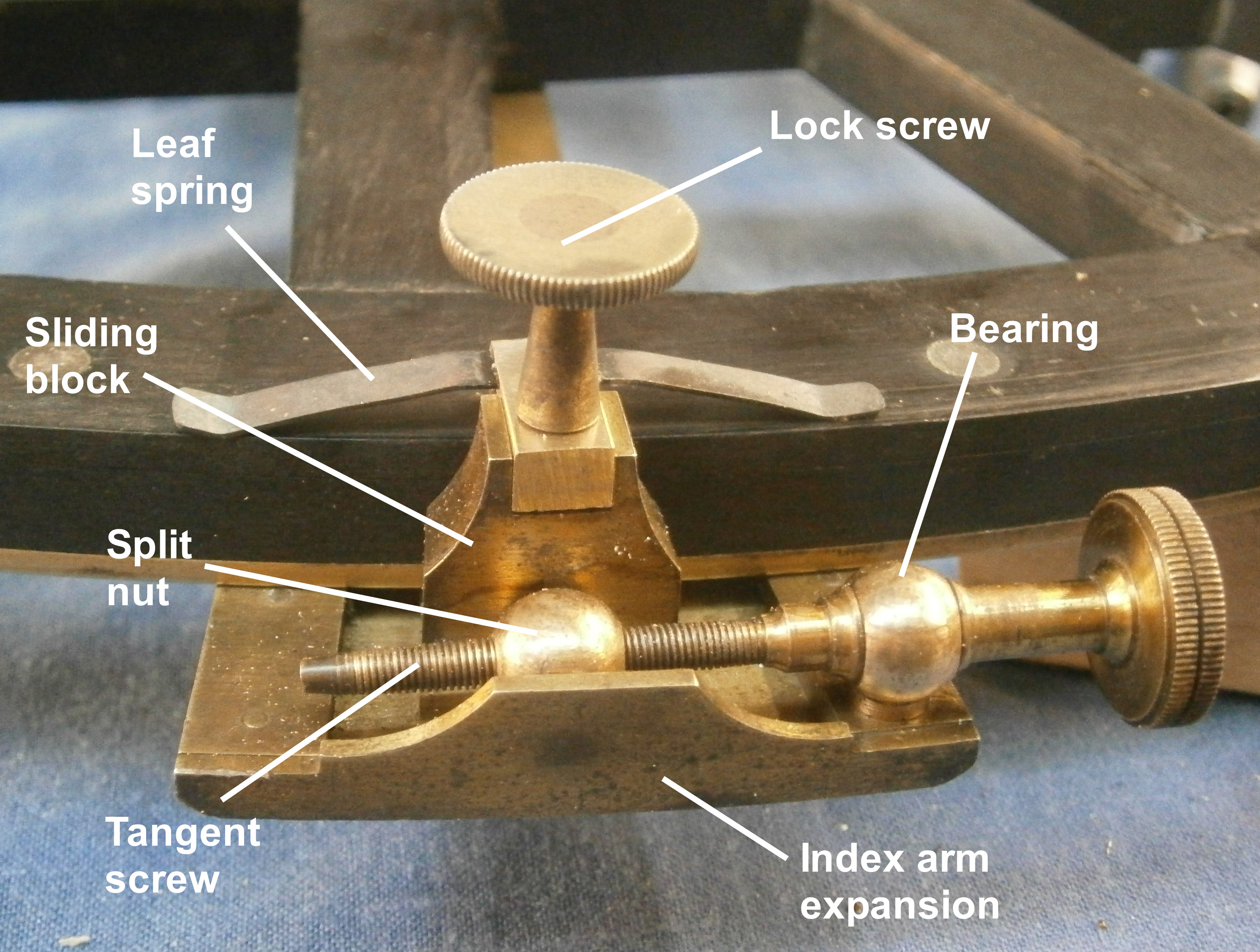
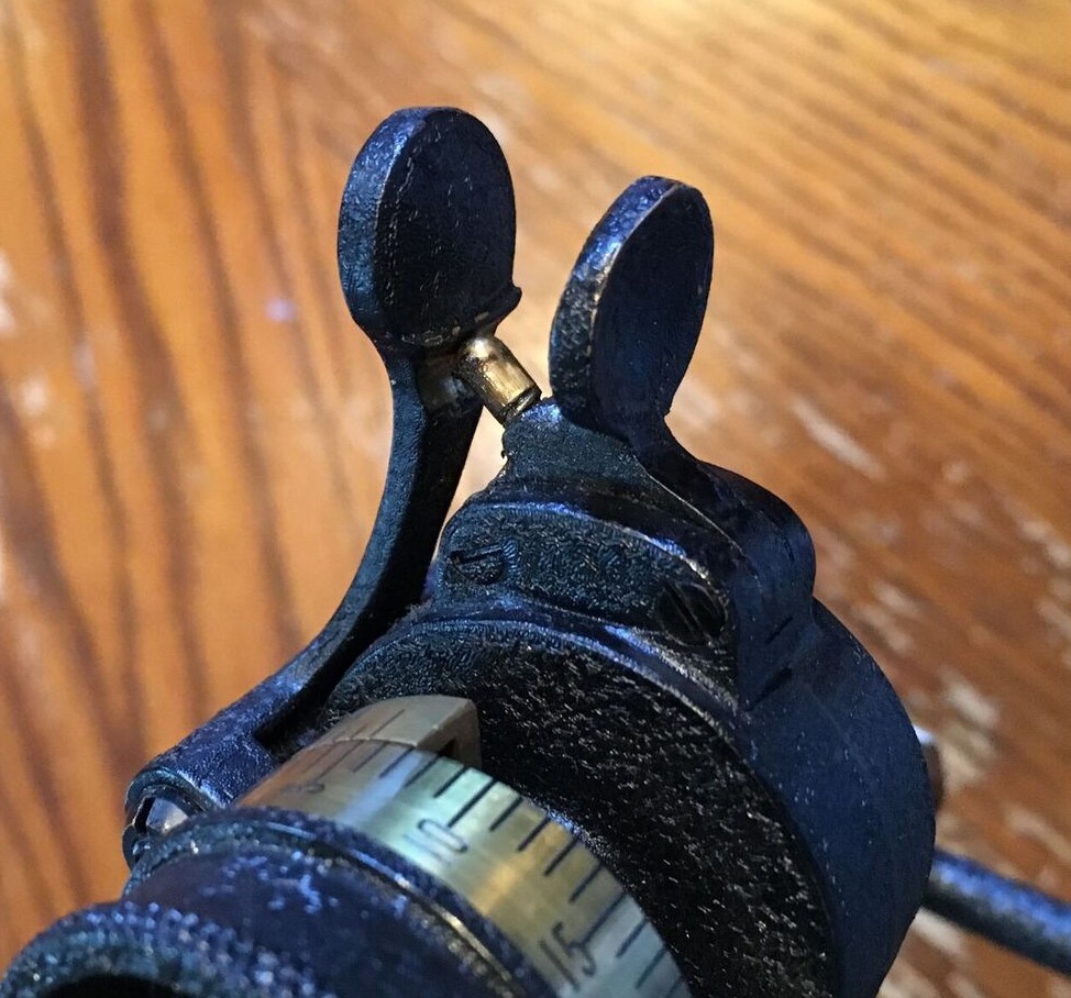
Figure 7: Controls and read-outs.

 A winding lever primes the integrator by ten strokes of the lever shown in Figure 7 and the integrator is started by operating the lever seen below the ten degrees adjustment knob. As in the Mark IX series this latter is pushed in against a spring load to rotate through ten degrees steps, governed by the three groups of holes seen in Figure 6. Further adjustment is by rotating the fine adjustment knob. Two windows give the instantaneous readings of the altitudes in tens and one degrees, and minutes are read from a further window. A fourth window behind the handle gives the integrator readout, which must be added to the tens of degrees shown in the top window.

The bubble unit

The unit, which is apparently taken directly from the Mk IX series,  is attached to the main body by two screws. It contains the bubble mechanism, a partially-reflecting mirror and a mirror/lens assembly (Figure 8). There is a slanted clear glass window on the front and a clear glass window at the rear for the eye.

Bubble unit labelled

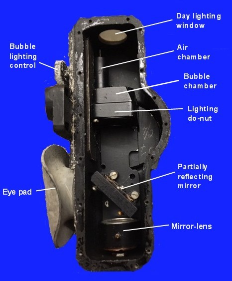
Figure 8: Interior of bubble unit.

The principle of the bubble unit is shown in Figure  9. The bubble is lit by daylight or a bulb via a Perspex do-nut directly below the bubble chamber.  Light rays, shown in yellow, then pass through a partially reflecting glass (shown in white) and are reflected by a mirror-lens combination whose focal length is the same as the radius of curvature of the top of the bubble unit. The bubble is in the focal plane of the mirror-lens, so the reflected rays emerge as parallel rays and are reflected into the eye via the partially reflecting glass. Rays, shown in red, from the observed body via the fixed “horizon” mirror pass straight through the partial reflector.  Effectively, the body and the bubble then both appear together at infinity at the eye.

Light path 2

Figure 9: Light paths in bubble unit

Despite the complexity of the sextant, and thanks to the use of a light alloy for all housing parts, the weight is just over 2 kg (2045 g) (including batteries). The German WWII Kreiselsextant (Gyro sextant) weighs by contrast 3 kg.

Lighting.

The bubble unit contains a light bulb and a simple intensity regulating mechanism. A strip with a vee-shaped slit, which is placed between the light bulb and the bubble unit, is moved up or down using a knurled wheel, seen labelled in Figure 8.

The left handle of the sextant is a battery holder for two C size cells. The rotary switch is operated by the left thumb. Turned clockwise it activates the bubble lighting and turned the other way lights the readouts as noted above. The bulb socket for the latter ought to be in the right hand side handle,  but it is missing on my sextant.
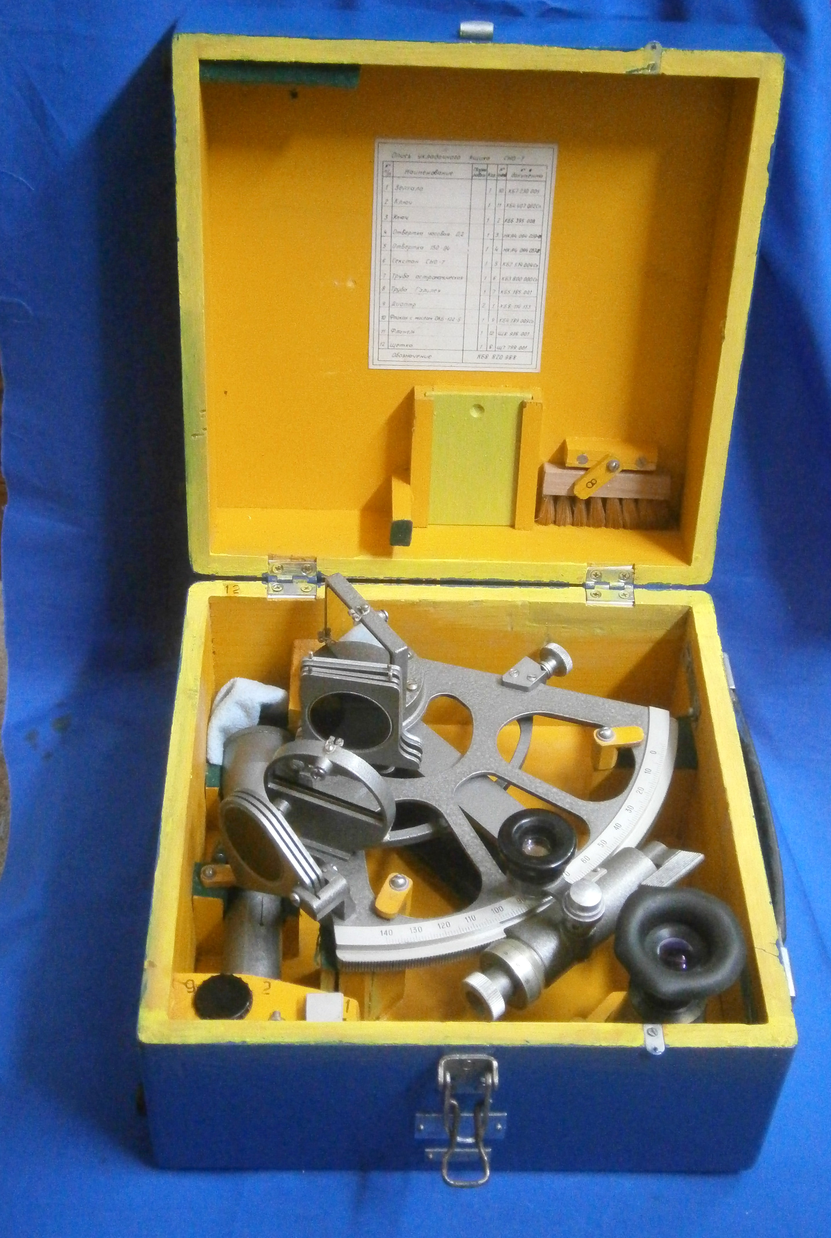
Box (Figure  10)

The box is made of solid mahogany, and has a stout leather strap over the lid, which can be used to carry it. There are green felt covered blocks to immobilise the sextant. There is a similar arrangement for the spare bubble/scope, which is secured by two keepers (one of which was missing). There are two battery holders, which are obviously intended for the now obsolete Eveready No 8 (3 V). When two batteries of size C are stored in each holder, the lower ones can only be removed by holding the box upside down.

In case

Figure 10: HMBS in its case.

History

I do not know the recent history of this sextant. It was donated to a Sea Scout group and sold on eBay to raise money. Its production date could be close to 1949, judging from the serial number (123).The National Maritime Museum at Greenwich has a Marine Bubble Sextant with serial number 114 with a certificate by Henry Hughes & Son dated 3 March 1949.

The certificate of my sextant is dated 18 July 1978, issued by Fenns, Farnborough Ltd. The sextant is also marked FEN/R/7/75.  Fenns did the calibration of the instrument for the Air Ministry, so it appears the sextant was still in the care of the Air Ministry in 1975.  Whether it was also in use is impossible to say. It seems likely that the sextant was sold sometime after 1978 and perhaps used at sea, as some external parts have corroded. However, this could also have occurred in humid storage conditions.

Concluding remarks

My impression is that the Hughes Marine Bubble Sextant was a product that was developed just too late to play a role in WWII, and which was unsuccessfully marketed after the war. Online, there is evidence of fewer than ten individual examples, two of which are in museums, three in past auctions and two in unrelated accounts. Some of these could even be the same. The two serial numbers I know are 114 and 123, which doesn’t tell much. This sextant used parts from the Mk IX (bubble unit, handle, general lay-out), but contains a completely new integrating mechanism. This mechanism may have found use in later aircraft or submarines sextants of the periscope type. It is clear that a lot of effort was put into designing and producing this sextant, so it must have been a disappointment for the manufacturer. Nevertheless, as a nautical sextant, it deserves a place on this blog. I have found a number of reports and articles on the internet which mention this sextant, but I’d like to hear from anyone who has more information.

If you enter this in the “Comments” section (below), I will forward your information to Jaap.

End note: [1] “Another enterprise of Plaskett and Jenkins was entirely successful in itself- the demonstration that the bubble sextant could be employed to aid the fixing of position of a submarine surfacing only at night when the sea horizon is invisible. Pleskett obtained highly accurate results from observations made on board a submarine off Start Point. As a result the ‘Hughes Marine Bubble Sextant’ made its appearance in 1944 and underwent trials, but apparently it never actually went into service.” (Biographical Memoirs: Harry Hemley Plaskett (5 July 1893 – 26 January 1980), Biogr. Mems Fell. R. Soc. 1981 27, 444-478, published 1 November 1981)

Readers who own a Mark IX series sextant who would like to know more about its construction, operation and restoration could do worse than buying a copy of my restoration manual. . See “My Bubble Sextant Restoration Manuals” for details.


A later Shackman sextant: a guest blog post.

14 03 2018

John Triplett recently wrote to me about a Shackman sextant that he had acquired and kindly agreed to write a guest blog post. In what follows, comments that I make are shown in blue.

It wasn’t very long after I first read Bill’s blog entry on Shackman sextants (https://sextantbook.com/category/shackman-sextant-and-link-to-ramsden/) that I had the opportunity to acquire one, and at an extremely reasonable price.  I found the design to be unique and interesting, and wanted to see it up close.  I found this sextant in a recent eBay auction that was listed referencing its reseller, Kelvin & Wilfrid O. White of Boston, and not its maker, D. Shackman & Sons (Figure 1).

IMG_3143_preview

Figure 1: The sextant sitting on its case.

In making some needed repairs (the index arm was bent away from the limb and had to be straightened), it soon became apparent that there are some design differences between Bill’s sextant and mine.  My sextant has a later serial number (No. 3236) than Bill’s (No. 2262), and that does seem speak to some of the differences between the two pieces.  As of this writing, there is another Shackman sextant being offered on eBay (again, resold by Kelvin & Wilfrid O. White) with a serial number (No. 2097) even lower than Bill’s, and having characteristics of Bill’s earlier number, specifically the short tail and leaf spring on the index.    No. 2097 also has a 30” micrometer with a single index line, not a 10” micrometer with a vernier, so, either different precisions were made by Shackman, perhaps some for survey purposes and others for higher precision needs in navigation, or the more precise vernier was a later revision. Most non-British makers had by this time begun to abandon the vernier, perhaps recognising that errors due to uncertainty about the dip of the horizon tend to swamp instrumental errors, which in any case are sometimes of the order of 30 seconds. If greater precision is needed, it is easy to estimate to 0,2 degrees, but such precision is likely to be devoid of meaning, given that the instruments were calibrated at only 30, 60, 90 and 120 degrees.

It generally appeared to be in fine condition, very clean, and showing very little use.  As for the needed repairs, my best guess is that this sextant was dropped early in its career at the US Merchant Marine Academy (as the property label on the box suggests), and, once the owners discovered the nature of the damage, it was simply shelved and forgotten.  (This long convalescence is further evidenced by the light damage to the lid of the box:  papers left on the top for a long period resulted in a stark bleaching/darkening pattern from a masked exposure (See Fig 1.)  Some disassembly was required, and this process uncovered some of the aforementioned differences.

The noted differences to my No. 3236 are:

  • ‘Paddle’ or ‘spoon’ grip extensions on the index and worm that improve manipulation and placement of the micrometer movement. One of the ‘spoons’ is deformed from the drop impact. See Figure 2 for close up view.
  • Copy of IMG_3295_preview

    Figure 2: Damage to release catch “paddle”.

  • The leaf spring has been replaced with a coil spring and plunger system that applies and maintains the pressure of the worm against the rack. The spring slides in and bears on a curved groove on the underside of the opposite paddle grip (Figure 3).
  • Copy of IMG_3294_preview

    Figure 3: Radial helical pre-load spring.

  • The index journal bearing system has seen a design change from the keyed washer to a spring and washer. (This was discovered when the index arm was removed from the frame for repair.) This is such a strange arrangement that I think it must be a later and rather clumsy repair. The washer under the head of the screw does not seem to have a square hole, so there is nothing to stop the washer from working the screw loose as the latter rotates with the journal (Figure 4).
  • Resulting in part from some of the above changes, the later sextant is positioned differently in the case to allow room for the elongated worm assembly.

Ironically, the strength of the ribbed arm casting Bill references in his original blog either worked well or not at all, depending on how you look at it.  It certainly preserved the alignment of the ribbed section of the arm, but fully transferred the bending moment into the weakest part of the arm at the hole for the journal mount.  In agreement with Bill’s assessment, this inherent weakness certainly makes the arm rib a questionable design point, and an overkill in manufacturing.

As for the spring-and-plunger system, this could be considered the Achilles’ Heel of this design.  The spring seems, to me, to be undersized and understrength. Once the spring becomes weakened to a critical point, there is no longer sufficient pressure to keep the worm against the rack; the user has to consciously add the needed force by hand. (Perhaps this too was a later repair. The spring seen in Figure 3 should perhaps be a larger one that fits outside the fitting in which the foot of the spring presently sits.)  It is especially annoying in that it occurs mostly when you are trying to use it normally.  The worm tends to fall away from the rack rather than onto it as does, say, a Hezzanith Endless Tangent Screw.  When turned ‘backwards’, the worm tends to ‘bite’ the rack and assist the spring in holding against it; when turned ‘forward’, the worm throws itself away from the rack and works against the spring.  This tendency was especially pronounced when I first received the sextant and the rack and worm were dry.  After the repair, a proper oiling to the contacting parts greatly mitigated this effect, but it is still noticeable

Another observation on an avoidable issue is the cork padding on the case top braces that contact the ends of the limb and the scope.  In addition to being glued down, they are actually nailed in place.  My example has some shoddy factory work in this aspect as one nailed head was bent over, leaving the edge higher than the cork.  The bronze surface at the left end of the limb is fairly mangled up from years of contact.  Was this really necessary?  Simply gluing it would have been just as effective and far more maintenance friendly for replacement.  Happily, the DS&S logo on the other end has fared much better. Shackman’s were manufacturing jewellers pre-war and probably did not make the case. It may well be that more careful woodworkers were doing war work deemed to be more important, e.g. making the all-wood Mospquito aircraft.

IMG_3302_preview

Figure 4: Shoddy workmanship.

The Shackman sextant is, aesthetically, a very attractive piece.  The simple and elegant all-black frame is highlighted only by the bronze of the limb and truly tangent micrometer (and maybe some exposed scope slide), which, while giving a striking appearance, is also quite functional and uniform for usage – the eye is naturally drawn to the scales that need to be read, and in somewhat of a progressive manner.  Also, for a non-engineering, non-optical firm, Shackman’s optics are very good (although they could have been subcontracted).  The telescope is very bright and clear, noticeably more so than those of my instrument by Buff & Buff, a maker known for excellent optics.  It is not a perfect design, as Bill points out, and suffers from some over complexity and confusing ideas that needlessly reduce its functionality in other ways and, quite possibly, its accuracy.  While the solid bronze casting is strong and rigid, its significant weight is felt rather quickly when trying to make an observation.  Still, I find it to be, overall, a rare, unique, and lovely design that makes for a desirable addition to a collection, and I am enjoying becoming more familiar with it.

Thank you, John.


Hughes and Son Admiralty pattern micrometer sextant

14 02 2018

I wrote about a Hughes and Son Admiralty pattern vernier sextant on 23rd June 2011, concentrating on its telescopes, its rising piece for the latter and its sealed mirrors. Recently, I acquired an Admiralty pattern micrometer sextant, probably part of a batch ordered in the closing days of WWII. The main difference is in the micrometer mechanism while the index arm bearing, mirrors, shades and telescopes are essentially the same as in the vernier sextant, certified in March of 1939, so I will not cover that ground again. Figure 1 shows the instrument as advertised by the seller, who seems to have photographed it through a light green filter. This explains the green cast to the blue-grey paint (I have removed the bright green background).

As bought

Figure 1: As bought.

The sextant was in a rather grubby condition, with paint beginning to perish and flake off in parts. I suspect it had been well-used, rather than spending nearly all its life in a cupboard.

Figure 2 shows the front view after a complete strip-down and restoration. In it I have labelled the main parts of a micrometer section for the benefit of newcomers to my site, and those who may not yet have purchased my book “The Nautical Sextant”, which looks in great detail at the structure of these instruments.

A 1 GA front

Figure 2: Front view of restored sextant.

Figure 3 shows the rear (or right hand side when in use). Here it is possible to see why this sextant, weighing in at 2.05 kg (4.52 lb) is so heavy. The cast bronze frame is very heavily ribbed compared to most other sextants, and features like the rising piece, the Index arm bearing cover and the complex arrangements for sealing the mirrors have all added to the weight. Earlier Hughes and Son instruments with scale lighting made the battery handle out of wood, but this one is of molded Bakelite with a brass battery cover. Happily, it contained no batteries nor signs of corrosion.

A2 GA back

Figure 3: Rear view of restored sextant.

Figure 4 shows details of the micrometer mechanism. The worm engages with the rack, which is cut into the edge of the limb. The rack is in essence a segment of a worm wheel having 720 teeth. Also cut into the edge of the limb is a groove which accepts the free edge of the two keepers. These prevent the index arm from lifting off the limb.

A3 micrometer detail

Figure 4: Details of micrometer mechanism.

The axial pre-load spring, which is shown out of place, is U-shaped with one upright of the U being forked to embrace the worm shaft and press on the flange immediately to the left of the thrust bearing. The worm shaft inside the bearing is conical, so it aligns the shaft axially and radially with a further bearing providing more radial guidance. This spring is a simpler solution to providing thrust pre-load than the more complicated systems used by Hughes and other makers prior to WW II.

The worm is held in engagement with the rack by a beryllium-copper radial pre-load spring. A simple cam bears on an arm extending from the swing arm on which the bearings and worm are mounted. When the release catch is operated, the cam causes the swing arm to rotate around a substantial bearing  and the worm disengages so that the index arm can be swung rapidly to a new position. When the release catch is let go, the spring swings the worm back into engagement with the rack and rotation of the micrometer drum provides fine adjustment.

There is a guard extending from the swing arm to provide some protection to the micrometer drum and the worm shaft. The shaft is often bent when a sextant is dropped or knocked and, as replacement parts have long been unobtainable, a whole worm and shaft have to be made. See for example “A Worm Turns” on this site on 23rd June 2011. The worm itself receives some protection from a sheet metal cover, seen in Figure 3.

Figure 4 shows the front of the index arm in the area of the worm. The screw that secures the axis about which the swing arm rotates has been removed to show a washer that is prevented from rotating by two pins into the swing arm, so that the screw can be adjusted to remove end shake in the bearing, while preventing movement of the swing arm from loosening or tightening the screw.

A4 micrometer front

Figure 5: More micrometer details.

There seems to be little point in providing a vernier to the micrometer, as the racks of this era often had errors in excess of 0.5 minutes and in any case, observation errors due to uncertainties about refraction and dip would often swamp instrument errors. Most makers after WWII abandoned micrometer verniers, but some were still made, presumably to satisfy conservative mariners and military procurement officers.

This instrument was provided with a fairly comprehensive kit of telescope and tools, shown in Figure 6.  Most mariners probably never used anything other than the Galilean (“star”) telescopes in the 20th century.  The higher powered ones were probably used mainly for artificial horizon shots in ports of known longitude to correct chronometers. This was made obsolete by the advent of radio time signals, but Tamaya in particular continued to provide them to the very end of sextant manufacture.

A6 telescopes etc

Figure 7: Ancillaries.

The eyepiece shades are useful for finding the index or zero error of the sextant by looking at the sun or moon, but again, most mariners would simply have used combinations of horizon and index shades, or used the horizon to avoid strain on the neck from looking up at the sun.

A very useful feature of the Galilean telescopes is the provision of hoods to prevent glare from around the horizon mirror reaching the eye, as the hood limits the field of view to the mirror alone (Figure 8).

A5 telescope hood

Figure 8: Telescope hood.

Figure 9 shows the sextant and its telescopes etc. in its fine mahogany case. As usual from about 1900 onwards, the corners have box comb joints. In all Hughes and Son sextants, the handle is on the right hand side, to avoid setting down the box on its hinges.

A7 in box

Figure 9: The sextant in its case.

Figure 10, shows the case standing on its left hand side. This, together with the hook latches which always face to the left, so that they tend to remain latched in the carrying position, identifies the sextant as a Hughes and Son, if it were not obvious from the circular “Husun” emblem attached to the index arm.

A8 latches

Figure 10: Hook latches in closed position.

If you have enjoyed reading this account, you will find much more of the same in my book “The Nautical Sextant”, but do not expect to find anything about in it about navigation. It is about the structure of the sextant.You can find plenty of positive reviews of the book on the amazon.com web site.


Carl Plath’s earliest sextant.

20 04 2017

This post was preceded by “C Plath Yachting sextant“ “Making a shades adjusting tool” and “Eighty years of Carl Plath Sextants”. Other posts on C Plath sextants may be found by entering “C Plath” in the search box on the right.

C Plath bought the business of David Filby, Hamburg’s member of Parliament, in 1862 and shortly after he disposed of the book and chart side of the business while retaining the nautical instrument side. Around about the time that he moved into the address known as Stubbenhuk 25, he acquired a dividing machine from Repsold, his former apprentice master, and began to make his own instruments, including sextants. A year or so ago I acquired an early C Plath sextant for a very modest sum on e-bay. It and its case were not in good condition and so I restored them, but other commitments have until now prevented me from writing about it.

Case as received

Figure 1: The case

Figure 1 shows the case as received, with shrinkage cracks in the top and signs of water damage. Much of the varnish had crumbled, so I stripped off all the old varnish from the outside, filled cracks, made good loose joints, re-lacquered the hardware, re-stained the mahogany and applied several coats of modern varnish to give the result shown in Figure 2. The corner joints are rebate joints, reinforced with steel pins at a time when most makers were using hand-cut corner dovetails. The top, however, is attached with brass screws, while the bottom is glued and pinned on, following the practice of nearly every maker throughout history. The pins tend to rust, being “out of sight, out of mind”.

Case restored

Figure 2: Case restored.

The interior  as received is shown in Figure 3. Apart from dust and many flakes of paint the green felt lining of the floor and roof of the box had decayed. Fortunately for the instrument, the pocket for the handle and the pads for the legs were attached by screws and glue which had not given way.

Interior as received

Figure 3: Interior as received

Cleaning the interior and fitting new felt  completed the restoration of the case, and restoring the instrument itself presented few problems as everything was present and intact. Figure 4 shows the back of the frame, which is a heavily ridged bronze casting. In the nineteenth and early twentieth century, a very large range of frame patterns was offered by the major makers, but it was not until the early part of the twentieth century that Plath left behind this initial pattern in favour of the ladder pattern, with the occasional three circle or “Dreikreis” pattern being offered (see my post for January 2010). Note the heavy re-inforcement in the areas where the telescope and horizon mirror brackets are mounted.

Rear as received

Figure 4: Frame before re-painting.

The traces of paint that remained were a pale green, but the sextant illustrated on page 50 of Friedrich Jerchow’s history of C Plath, From Sextant to Satellite Navigation, is painted black, so I surmise that the green represents perhaps a primer coat. At any event, I stripped it all off and re-coated the parts black, taking the illustration as a pattern. Figure 5 shows the sextant in its case after restoration.

Interior restored

Figure 5: After restoration

Figure 6 shows the kit of telescopes and other parts supplied. Well into the twentieth century, sextants were often supplied with several telescopes and supplementary eye-pieces. I doubt that there was ever a time when most of them were used at sea. The 6 x 16 Galilean telescope has a tiny field of view and the 10 x 17 inverting telescope is no better. There may have been a time when they were used on land with an artificial horizon to check on the rate of chronometers in distant ports of known longitude, but at sea the 3 x 28 Galilean was probably the one used most, with the ‘zero magnification” sighting tube being substituted in rough weather. The eyepiece shade may have been used to check index error using the sun, but again, most people would probably have used the horizon, as it is easier on the neck to do so.

Telescope kit

Figure 6: Telescope kit

The shades and mirror brackets are perfectly conventional and avoid the complications used by French makers in particular and also by Brandis and successors. The tangent screw is of some interest and is shown complete in Figure 7. With slight modification it was also used in the Dreikreis sextant before the micrometer sextant was developed by C Plath around about 1907.

Tangent screw

Figure 7: Tangent screw

The spring box, which I have called a “sliding block” in different designs, slides in a close-fitting pocket on the rear of the index arm expansion and can be clamped to the limb using the clamp. A leaf spring keeps the box in place when un-clamped. The end of the tangent screw bears on a tongue projecting from the back of the index arm against the pressure of a coil spring within the spring box. thus, as the screw is turned, the index arm moves along the arc in slow motion. On releasing the clamp, the index arm can be swung rapidly by hand. Figure 8, which shows the mechanism exploded, may help to make this clearer.

Tangent screw exploded

Figure 8: Tangent screw mechanism exploded.

The mechanism for raising and lowering the axis of the telescope so that more or less light from the horizon can enter it is shown in Figure 9. It represents an intermediate stage of complexity on its way to the simplicity of the second half of the twentieth century.

Rising piece

Figure 9: Telescope rise and fall.

A telescope bracket having a vee groove and flat machined into it is attached to the frame of the sextant. The rising piece of the telescope has a matching vee and flat to guide it up and down. The lower end of the rising piece has a threaded hole for a screw that is held captive in the telescope bracket, to that when the screw is rotated, the rising piece rises or descends. A clamp holds the rising piece at the selected height.

Arc and name

Figure 10: The arc.

The silver arc, let into the bronze limb, is divided to 10 minutes (Figure 10) and the silver vernier allows readings to ten seconds, though, as with many similar verniers, it is usually impossible to decide which particular pair of lines coincide. It is easier to decide which two pairs of lines just do not coincide and to choose the middle value between them. It bears the C Plath name in flowing copper plate script, a feature of Plath’s earlier sextants.

Serial and S

Figure 11: Serial number and inspection mark.

 Dr Andreas Philipp has kindly provided me with the date of early 1899 for the instrument, or at least, its certification by Deutsche Seewarte. He tells me that both “S” and “D S” were used irrespective of date. He also sent me an illustration from Plath’s number V catalogue of  1906, which I reproduce below (click on this image to enlarge it). Based on the D.S. records, it seems that between 1876 and 1901, Plath produced an average of only 27 sextants per year.

Cat photo 001.JPG

Catalogue entry 1906 (Courtesy of Dr Andreas Philipp)


A Francis Barker Yachting Sextant.

17 02 2016

This post also appears under the category “Box sextants”. All figures may enlarged by clicking on them. Use the back arrow to return to the text. 

Francis Barker, born in 1819, flourished in Clerkenwell Road, London from about 1840 until his death from tuberculosis in 1875. He was succeeded by his sons and the firm continued under his name until about 1932, when it was taken over, eventually by Pyser CGI of Edenbridge, Kent. Barker’s main products were magnetic compasses and sundials, though they did branch out into jewellery making in the late nineteenth century. Magnetic marching compasses continue to be made under the Francis Barker name. Probably in the second half of the 1970s they began to produce a yachting sextant and production probably continued for about ten years. Celestaire bought the entire remaining stock of 36 instruments in the late 1980s and disposed of all of them. They are relatively rare.

The sextant was a box or drum sextant and was contained in a heavy saddle leather case, retained by two press studs (Figure 1). It is quite difficult to extract it from its case without pulling on the strap and putting its stitching at risk. The small handbook reommends putting the strap around the user’s neck to guard against accidentally dropping it overboard.

In case

Figure 1. Sextant in its case.

Figure 2 shows the instrument out of its case, and Figure 3 shows the general arrangement with the principal parts labelled.

OLYMPUS DIGITAL CAMERA

Figure 2: Sextant out of its case.

GA

Figure 3: General arrangement.

The operating parts are contained within a light alloy drum 76 mm in diameter and 50 mm high. The main scale, 45 mm in radius, is divided to half degrees, and there is a vernier divided to single minutes. The setting knob contains a planetry drive, which gives a slow motion when rotated slowly and a fast motion when rotated more quickly.

There are two interchangeable peep sights (Figure 4), each with a 1.5 mm in diameter hole. One is provided with a shade for use when the horizon is bright. Many older users may have small central cataracts in their eyes and they may find that the hole in the sight is small enough to cause a shadow of their cataracts to partially obscure their view, in which case there is nothing to be lost by opening out the hole to, say, 2 mm, to allow more peripheral rays to by-pass the cataract. The two levers shown bring index shades into the light path.

GA with sights

Figure 4: Peep sights and shades.

The internal arrangement for these shades is shown in Figure 5. According to Ken Gebhart of Celestaire, there are at least 18 units in ciculation in which full glasses were installed by mistake, instead of the half-glasses shown.

Shades

Figure 5: Horizon shades.

Figure 6 shows the general internal arrangement.

GA internal

Figure 6; General internal arrangement.

The index mirror is adjusted for perpendicularity by the usual method (Figure 7) and Figure 8 shows how the mirror bracket is tilted by means of opposed screws which rock it about a horizontal axis formed by the heads of two grub screws.

Perp adjust

Figure 7: Aligning index mirror for perpendicularity.

Index mirror mount

Figure 8: Index mirror mounting and adjustments.

The method of adjusting the horizon mirror for index error can be seen reflected in the index mirror in Figure 7 and a close up is shown in Figure 9. Side error is taken care of by the same method of rocking about an axis by two opposed screws , while index error is removed by rotating the whole mirror bracket via a metal gear meshing with a nylon gear.

Horizon mirror adj

Figure 9: Horizon mirror adjustments.

The squared heads of the adjusting screws are on the face of the sextant and are adjusted by means of a key that unscrews from its nearby housing (Figure 10). The slotted screw must be tightened before removing side error and then slackened off a little to allow adjustment for index error. This may introduce some more side error, so the cycle may need to be repeated a few times, after which the slotted screw is carefully re-tightened.

Adjusting screws

Figure 10: Heads of adjusting screws

The scales are read with the help of a plano-convex lens of about 25 mm focal length (Figure 11). The divisions lack a little of the crispness seen in earlier box sextants. The rather small radius of the arc, of 45 mm as opposed to about 160 mm for a full size vernier sextant, makes deciding which line on the vernier coincides with a line on the main scale somewhat problematical. In the photograph, which gives a fair representation of what is actually seen, at least three lines coincide, so perhaps the best that can be done is to decide which two pairs just do not coincide and to chose the lines midway between the two pairs.

Scales

Figure 1. Sextant in its case.

If you enjoyed reading this post, you may also enjoy my books “The Nautical Sextant” and “The Mariner’s Chronometer” (www.chronometerbook.com).

.