An Hungarian sextant via Bulgaria

21 09 2011

Previous posts in this category cover:  “A C19 Sextant Restoration” , “Making a Keystone Sextant Case” , “Restoring a C. Plath Drei Kreis Sextant” , “Heath Curve-bar sextant compared with Plath” , “A Drowned Husun Three Circle Sextant”, ”Troughton and Simms Surveying Sextant” , “A Sextant 210 Years On” , “A fine sextant by Filotecnica Salmoiraghi” and “A British Admiralty Vernier Sextant.”

 A few weeks ago on e-bay, I bought a sextant that was said to be Bulgarian. The seller was Malaysian and I seemed to have been the only bidder for this interesting-looking instrument so that my finances stretched to its purchase. The pleasant and communicative seller initially sold it without a case, as it was broken (Figure 1), but I contacted him to ask him to keep the case and send it with the sextant, which he very happily did. When it arrived, the brass placard on the ruined pinewood box read “Gamma Budapest”, but there was a stencilled Cyrillic word on the top which, if it were Russian, would transliterate as something like shtuomluskhii, which does not appear in my rather small Russian-English dictionary. The Hungarian language uses Roman letters and its nearest neighbour with a sea coast, onto the Black Sea, and that also uses Cyrillic letters, is Bulgaria. Hungary itself is totally landlocked, but it has not always been so. However, the Treaty of Trianon following the First World War removed huge fragments from the Kingdom of Hungary, and gave them to Austria, Czechoslovakia, Romania, Bulgaria and the former Yugoslavia. Hungary had the misfortune to be on the losing side in the Second World War too and lived under the heavy hand of the Soviet Union for many years after.

Figure 1 : Base of ruined case

Description

As a guess, I would say that the sextant was made in the years following WWII, as the shades and micrometer mechanism are identical to those of C Plath sextants of the time, many parts of which seem to have reached Britain and the USSR as plunder and reparations. The frame, however, is of a most unusual form, cast in aluminium alloy with the rack cut directly into the frame (Figure 2). The lower case Greek letter gamma (γ) forms part of the frame and there is of course a star (though not a navigational one), gamma sextans to complete the allusion in the name. The frame is covered in a thick and tough coat of black gloss paint, so it is not possible to judge whether the frame was die cast. Very few must have been made , so that it would be hard to justify the cost of the die. More likely, it was sand cast as the front of the frame (except for the arc, which has been machined) is not flat.

Figure 2 : Sextant as received

Cutting the rack directly into the frame is not a problem in itself, but I was taken aback to see that the worm was made of steel rather than the more usual brass used on bronze racks or hard bronze used on aluminium racks. The threads bore a light patina of rust (Figure 3). Almost as undesirable, the brackets for the shades are cast as one with the frame (Figure 4), so that if part should get broken, and shades are very vulnerable to damage, it is practically impossible to make good the damage. The mounting of the shades in the brackets is standard for Plath sextants of the time, on a cylindrical pin prevented from rotating by a crossed taper pin and adjusted by closing up the cheeks of the bracket with a screw let into the end of the pin   A refinement is missing : that of a key way in the pin and keys in the washers that separate the shades, so that rotation of one shade is not transmitted to an adjacent one.

Figure 3 : Steel worm.

Figure 4 : Shades mountings.

The mirror brackets show signs of internal machining so that they are either die castings or  have been cast separately and machined afterwards. Of interest to lovers of detail are the clips for holding the mirrors in place and the method of locking the adjusting screws . The clips (Figure 5), which bear conical points, are fastened to bosses on the front of the brackets, whereas practically all other makers secure them to the edges, where there is little metal and a high risk of stripping threads. The adjusting screws (Figure 6) bear directly opposite the points, passing through a threaded hole in a separate brass piece and then through a clearance hole in the back of the mirror bracket. The brass piece is secured to the back of the mirror bracket and is split so that a pinch screw can close it up and lock the adjusting screw. This is a very practical and effective arrangement though of course it adds to the cost of the instrument.

Figure 5 : Mirror clips.

Figure 6 : Mirror adjusting acrews.

The index arm and its bearing are conventional. The taper of the bearing is typical of C Plath practice, rather steeper than in English sextants. and, again as in C Plath sextants, the index arm expansion that bears the micrometer mechanism is a separate piece, attached to the arm by four screws. Like war time Plaths and early US BuShips Mark II sextants, there is no micrometer vernier and the drum is divided to half minutes. The Galilean (star) telescope is 3 x 40 mm aperture and has  binocular-type eyepiece focussing.

Restoration

Apart from making two new pieces for the floor of the case, and reassembling it, there was relatively little for me to do in the way of restoration once I had taken the instrument apart and cleaned all its parts. I could not, however, leave a rusty steel worm in place and so I made and fitted a new one of brass (Figure7) .  I have given  an account of making a worm in a separate post (6 July, 2009, A worm turns). The micrometer drum had weathered to a dark nicotine brown, but careful cleaning and rubbing with 1000 grit emery paper converted it to a much more legible light orange colour. The telescope rising piece was also, surprisingly, made of steel, but I felt that it could be left, as it is a non-critical component. A thorough cleaning of the lenses of the ‘scope brought about a pleasing increase in clarity of view.

Figure 7 : Two worms and their shafts.

Calibration

The instrument quality is generally rather good, so I was disappointed to find that it is the most inaccurate sextant that I have calibrated so far, though, paradoxically, it is quite precise. The reading of the sextant give values that are between 14 and 104 arcseconds (0.2 to 1.7 minutes) in error, but when the errors are plotted on a graph, the graph is very close to a straight line, so that the errors can be allowed for to give  readings that are very close to the correct ones. I will be giving more details of this and its probable cause in a separate post in the Chasing tenths of an arcminute category, but Figure 8 shows the table and graph of errors with a line of best fit plotted on the graph. Unfortunately, the errors are non-correctable, but an accurate estimate of the reading may be had by applying a correction from the graph.

Figure 8 : Calibration table and graph of errors.

The final photograph, Figure 9,  shows the completed sextant in its repaired and re-varnished case.

Figure 9 : Completed restoration.


István Benkó has kindly sent me the following information about the makers of the sextant: Gamma Optikai M?vek was a Hungarian camera maker in Budapest. It was founded as Gamma Finommechanikai és Optikai M?vek Rt. (Gamma Works for Precision Mechanics and Optics Ltd.) in 1939. Its most famous cameras are the Pajta’s in 1955 and the technically advanced SLR named Duflex designed by Jen? Dulovits in 1947.


British Admiralty Vernier Sextant

23 06 2011

Previous posts in this category cover:  “A C19 Sextant Restoration” , “Making a Keystone Sextant Case” , “Restoring a C. Plath Drei Kreis Sextant” , “Heath Curve-bar sextant compared with Plath” , “A Drowned Husun Three Circle Sextant”, ”Troughton and Simms Surveying Sextant” , “A Sextant 210 Years On” and “A fine sextant by Filotecnica Salmoiraghi.”

The Admiralty ordered sextants from Henry Hughes and Son and bought them provided that they met Admiralty specifications as determined by the National Physical Laboratory at Teddington. Pre-World War II they were given on Admiralty Form 575, but I have not been able to find a copy to discover exactly what the specifications were. Presumably they were exacting and conservative.

Figure 1 : Inspection certificate of sextant number 222**

In the late 1930’s  a batch of vernier sextants was ordered from Hughes and Son and in the early 1950’s another batch, was ordered, this time of micrometer sextants. Except for the rack and micrometer mechanism, they had many things in common: the form of the frame, the mirrors and their mountings , the shades and their mountings and their telescopes. The frame is the classical A type frame, of bronze, heavily ribbed and  the shades are conventionally mounted, but the mirrors are circular and sealed and the telescopes have coarse interupted threads that allow them to be rapidly mounted and dismounted. The sextant can be returned to its case with the index arm set in any position except at the extremes, said to be an  important practical point if a question about a reading occurs when calculating a position line (though most people would try to average several sights of the same body, when gross errors would be noticed).

A few weeks ago, I came upon an Admiralty pattern vernier sextant in good condition and enjoyed restoring it to a near-new condition, at the same time observing points of difference with other instrument types.  Figure 1 shows a general view of the instrument, with the star telescope fitted. In the background is the inverting telescope with an extra, high-power eyepiece ,  two eyepiece shades and an adjusting pick. Note the unusual mirror mountings and magnifier mounting.

Figure 1 : Admiralty Pattern sextant and accessories

 
Telescopes and their mounting
The sextant was issued with a 2 x 40 mm Galilean star telescope and a 5 x 25 mm inverting telescope, the latter provided with an extra eyepiece to give a magnification of about x 10. Normally, this high powered eyepiece would be provided with a pair of parallel cross hairs, so that the collimation of the telescope could be checked, but only traces of these remain. Possibly they were removed as being unnecessary, as it is not possible to adjust the collimation on this instrument.
 
Many Galilean telescopes are provided with an eye lens that restricts the field of view, but in this instrument (Figure 3) , the eye lens is 19 mm in diameter, so that even spectacle wearers can take advantage of  the exceptionally wide field of view that I measured as 19 degrees.  Opinion of the time seems to have been divided on the power that the star telescope should have, as, for a given diameter of objective lens, the field of view decreases as the magnification increases. Heath and Co., Hughes’s main competitor in England, noted that the diameter of the  fully dilated pupil of the eye at night was 8 mm and that this regulated the amount of light that could be received by the eye. There was no advantage, they said, in having the 20 mm diameter pencil of the low-powered telescope, as the eye could not take advantage of it. It was their view that if the emergent pencil and the pupil diameter were about the same, all the light gathered by the objective lens would enter the eye and “both the star and the horizon would appear comparatively brightly illuminated.”  Hughes’s standard star telescope was 2.5 x 30 mm as against Heath’s 3 x 30mm, so they were not too far apart. If the Admiralty wanted a 2 x 40, it was presumably felt that the wide field of view and exit pencil made quite certain that the brightest possible image of the horizon could be obtained even if some of the entering light got wasted.
 

Figure 3 : Galilean star telescope

 
In daytime, the amount of light entering the telescope is not a critical factor, and a higher magnification allows one to judge better when the image of the sun, moon or, occasionally, Venus is touching the horizon. The bodies are brighter too, so that finding them with a restricted field of view is easier. However, with a small field of view, it is easy to lose the body in bringing it down to the horizon. The inverting telescope (Figure 4)  has a measured field of view of 7.6 degrees, about the same as a 6 x 30 monocular, and bringing the body down in rough weather without losing it is much easier. For practical purposes, the high powered eyepiece would seldom be used at sea, its main purpose being for checking collimation and perhaps ocasionally when using an artificial horizon on dry land in an out-of-the-way place.
 

Figure 4 : Inverting telescope

 
As I have noted above, there is no provision for adjusting collimation. Instead, the robust triangular rising piece is manufactured so that it is square to the plane of the arc of the sextant  (Figure 5) and likely to remain that way, as wear in the area should be negligible.
 

Figure 5 : Checking squareness of face of telescope ring.

 Figure 6 (below) shows the internal structure of the mechanism. The socket is firmly attached from behind the frame by three screws and sits in a machined circular pocket that ensures that it is square to the frame (Figure 7). The socket is made in two parts : one with a triangular holes broached through it and a disk with a round hole for the shank of the feed screw. The two are silver-soldered together and it is impossible to see the joint.  It would not be possible to make the triangular hole without this artifice. The feed screw is held captive in the disc, between the triangular flange and the knob, which has the familiar square. This allows adjustment to remove backlash by tightening the axial securing screw.
 

Figure 6 : Rising piece mechanism.


Figure 7 : Attachment of rising piece mechanism to frame.

Figure 4 shows the external interupted thread on a telescope and the internal thread can be seen in the interior of the very substantial telescope ring in Figure 5 .  Alternate one-sixths of the thread are machined away, so that the telescope can be inserted with the white dots lined up and secured in place by rotating through less than one sixth of a turn. The Admiralty  may have decided on  this device by analogy with  the interupted threads of the breech closing mechanism of naval artillery, but Hughes also used it in their higher class sextants made for civilian use.
 
Index mirror mounting
The index mirror is sealed inside its bracket and is not adjustable. Like the telescope mounting, it was manufactured correctly in the first place and, short of breakage, would remain square to the plane of the arc throughout its life. The rear of the bracket bears the statement ” Pat. No 472814, which was accepted in 1935. Figure 8, extracted from the patent document, shows how the silvered rear of the mirror was protected from the effects of salt water by holding it against a “resilient washer” by means of a threaded ring with a lip that bears on the periphery of the mirror.
 

Figure 8 : Extract from patent on sealing mirrors

 
Horizon mirror mounting
 This is altogether more complex, since light has to pass through it. Figure 9 shows the mounting exploded. In the left half of the figure the mirror can be seen. A disc of optical glass is cemented to the back of the mirror to protect the silvering and the edges of the mirror and glass where they join is bevelled, so that there is a thin wedge of cement to prevent infiltration of water. There are four dots of silver on the rear of the mirror (Figure 10), presumably to ensure that the cement layer was of uniform thickness , to prevent any prismatic effect. The sandwich is contained in a cell and retained there by a threaded ring and washer.
 

Figure 9 : Horizon mirror mounting exploded.

Figure 10 : Rear of horizon mirror sandwich.

 
The right half of the photograph shows how the cell is attached flexibly to the bracket, by means of two slightly curved leaf springs, attached at their ends to the cell and in their middle to the bracket.  The usual two adjusting screws bear on the cell to adjust out side and index error, and are provided with protective screw-on covers. 
 
The bracket bears the caption “Patent number 30340/34”, but this is in fact a patent application number, one higher than the application number for the index mirror patent. I have not been able to trace the patent itself and assume that one was never granted, possibly because some important aspect had already been anticipated.
 
Magnifier mounting
 
Many manufacturers contented themselves with mounting a magnifier at the end of a swinging arm, centred about two thirds of the way down the index arm, with the centre of the lens approximately over the junction of the arc and vernier scales. Obviously, at each end of the vernier scale, the lens centre would be a little out of line with this junction.  When a Ramsden type of compound magnifier was used, this was of little consequence, as the Ramsden provides a relatively flat field, but many cheaper instruments were provided with a simple plano-convex lens, which suffers from quite severe off-axis distortion.
 
While Hughes provided a Ramsden type magnifier in their top-of-the line pre-WWII vernier sextants, in this Admiralty pattern sextant, there is only a simple magnifier, but it is carried in a substantial mounting that allows the lens to follow the curve of the scales (Figure 11).
 

Figure 11 : Magnifier mounting

 A curved bed is mounted on two pillars and a short dovetail slide with keeper underneath carries the magnifying lens mounting. An elegant little brass knob completes the assembly.
 
Tangent screw and clamp
 The tangent screw mechanism is one that was (and is) commonly used in theodolites for obtaining slow motion. I touched on it briefly in my description of a Troughton and Simms sextant and I repeat the description here (see Figures 12 and 13).
 
A block that can slide in guides on the back of the lower end of the index arm can be clamped to the limb. A tongue or lug projects from the sliding block and is sandwiched between the end of the tangent screw and an opposing spring, both of which are contained in a tubular frame that is secured to the lower end of the index arm. When the clamp is released, the index arm is free to move over the arc. When it is secured to the limb by the clamp, the tangent screw can be used to make fine adjustments, and the spring inside the spring box provides motion in the opposite direction. It also takes care of backlash, which can be an annoyance in a vernier instrument, even though it does not affect the accuracy of the reading.  Other makers were content to leave the ends of the dovetail slide open, but in this instrument they are closed off with end pieces.
 

Figure 12 : Tangent screw mechanism in situ.


Figure 13 : Tangent screw mechanism exploded.


 Finally, Figure 14 shows the instrument in its refurbished substantial mahogany case. Like all Hughes sextant cases, the handle is on the right hand side, so that the case is not set down on its hinges, and the recessed hook latches face to the left, so that gravity keeps them closed when the case is carried by the handle. The handle is of the type commonly found in military chests and is usually let into the wood, but that detail has been omitted in this case. A “belt and braces” approach to securing the sextant has been adopted, with a pocket and boxwood retaining latch for the handle, while three felt covered pads in the lid hold the instrument secured when the lid is closed and latched. The corners have box-comb joints and top and bottom are, as in most sextant cases, glued and screwed on with counter sunk brass screws.
 

Figure 14 : Sextant in case

 
 If you have enjoyed reading this account, you will, I am sure, enjoy reading my book The Nautical Sextant, available through booksellers, from Amazon or direct from the publishers, Paradise Cay and Celestaire. Intending buyers in Australia and New Zealand may find it interesting to Contact me, as I am able to offer them a discount on the published price.


A Fine Sextant by Filotecnica Salmoiraghi of Milan

5 10 2010

The preceding posts covers “A C19 Sextant Restoration” , “Making a Keystone Sextant Case” , “Restoring a C. Plath Drei Kreis Sextant” , “Heath Curve-bar sextant compared with Plath” , “A Drowned Husun Three Circle Sextant”, “Troughton and Simms Surveying Sextant”  and “A Sextant 210 Years On”.

A little while ago, I felt privileged to be able to overhaul an uncommon sextant, made by La Filotecnica Salmoiraghi of Milan in Italy. A first glimpse of the case hinted that the instrument inside would be of very high quality, as attention to detail had been paid in making the case. A heavy cast brass latch and two chromium plated brass hooks held the case closed, the slots in the screw heads that held the top of the lid in place were all lined up parallel to the edges and the hinge was a piano hinge extending nearly the whole breadth of the case. As final details, the brass key bore the maker’s initial (Salmoiraghi) and a brass plate was let into the front for the owner’s name.    

Figure 1 : Exterior of case

  La Filotecnica was founded in 1865 by Ignazio Porro ( 1801 – 1875), the inventor of the prismatic binocular. Porro served in the Italian Army before retiring with the rank of major, in 1842. He worked in Paris for about fifteen years, producing a variety of surveying and optical instruments before returning to Italy in 1861. He founded the Officina Filotecnica at first in Turin and then, in about 1865, in Milan. The factory combined production with what we would probably call nowadays a school for apprentices. Porro seems to have had a poor head for business and in 1870 one of his pupils, Angelo Salmoiraghi (1848 – 1939), took over the ownership of the business after a short period in management. Under Salmoiraghi as La Filotecnica Salmoiraghi,  the firm became one of Italy’s leading producers of optical and precision instruments. Today, the firm, trading as Salmoiraghi e Vigano, manufacturers principally spectacles and markets optical goods made by other firms..    

Figure 2 : Name plate.

Opening the case reveals a clever way of  retaining the sextant in the case. Unusually, the instrument can be placed directly in the case without letting go of the handle. A further very practical aspect to the design of the case is that the sextant can be replaced with the telescope in place. Closing the lid brings pads of very fine brown felt into play to secure instrument and accessories securely in place. A finely crafted stand receives the sextant, location being ensured by large wooden spigots that fit into the circles of the frame, while the telescopes fit into well-thought-out pockets (Figure 3).    

Figure 3 : Contents of case

  The mirrors, shades, the index arm and its bearing are all conventional. The horizon mirror is fully silvered so that the horizon is viewed viewed directly, without passing through an unsilvered part of the mirror. This would be a disadvantage with a Galilean (so-called “star”) telescope, in which each half sees its own field of view, so that without reflection from the clear glass of a half silvered mirror there is little overlap of the direct and reflected images. However, this sextant is provided only with a 6 x 30 mm prismatic monocular and a 10 x 17 mm inverting telescope, both Keplerian in principle, so that there is very adequate overlap of the images. There is a sighting tube for use when surveying or taking sights in heavy weather. In what follows, I will describe only what is unusual or unconventional.    

Figure 4 ; Frame of sextant.

The bronze frame (Figure 4) is of about 162 mm radius and is of three-circle pattern. It resembles superficially the three-circle instruments of Hughes and Son (see my post of 18 Feb 2010) and of C Plath (see my post of  24 Jan 2010) but there are differences in detail. It is heavier than other frames of its radius, weighing in at a hefty 750 G compared to the Hughes frame of 600 G. Sailors who like a bit of “heft” in their sextants will not be disappointed by the Filotecnica as, equipped for viewing with the monocular, it weights 1750 G (3lb 14oz) versus the Hughes at 1500 G (3lb 5 oz). Both are equally and very resistant to flexing. With the exception of the arc, which is chromium plated, the face of the frame is painted semi-gloss black, while the rest is painted in a black wrinkle finish. The index arm bearing is attached with screws from the back.    

In a general view of the instrument (Figure 5), one is immediately struck by the length of the micrometer shaft. Unlike almost every other sextant of this pattern, the micrometer worm is not tapered. While it is easier to make a cylindrical worm, the penalty is that either the micrometer drum has to be smaller to fit beneath the curve of the limb or the shaft has to be longer and therefore more vulnerable to damage.    

Figure 5 : General arrangement, front view.

 The worm shaft runs in plain parallel bearings mounted on a swing arm chassis, which pivots around the ends of two cone-pointed screws attached to the back of the index arm expansion (Figure 6). These latter screws can be adjusted to remove all end float and then locked in place. In this instrument, the release catch swings the worm at right angles to  the plane of the arc (Figure 7), in contrast to most other sextants, which swing it out of engagment parallel to the plane of the arc. There is no  adjustment for end float of the micrometer shaft, however, and absence of float, equally as undesirable here as in the swing arm chassis, depends entirely on skilled fitting, rather than using a preload spring like most other instruments .

Figure 6 : Micrometer mechanism


Figure 7 : Swing arm detail

Figure 8 shows how thrust in either direction is received on collars on the shaft and the inner ends of the plain bearings. Upon testing by directing an autocollimator on to the index mirror and approaching zero with the micrometer reading increasing and  decreasing, I could detect no difference in the autocollimator readout, indicating a complete absence of measurable backlash (unwanted longitudinal shaft movement) with a precision of better than 1 arcsecond. This absence of backlash, besides indicating immaculate fitting of the shaft and bearings, is of course necessary to make meaningful the non-adjustable error readings shown in Figure 9. Almost needless to say, these are quite exceptional results for a micrometer sextant of 1948 date. The pitch of the worm is 1.4 mm giving a pitch circle radius for the rack of (1.4 x 720)/2 pi = 160.43 mm.

Figure 8 : Micrometer worm shaft bearings.

Figure 9 : Chart of non-adjustable errors

The method chosen to mate the telescope and sighting tube to the sextant seems somewhat over-engineered. The tubes are fitted with  heavy brass collars that have  coarse interrupted threads on the outside. The rising piece has the usual arrangement of a tiltable bush for collimating the telescope, with the addition of a large captive nut having a female interrupted thread on the inside. A stout pin projects from the face of the bush to locate in a hole on the telescope collar, so that the thread starts correctly and attaches the ‘scope to the rising piece with one sixth of a turn. Figures 10 I hope make this clearer.

Figure 10 : Telescope attachment

But there is further complication in the telescope bracket. It has a female vee into which the vee on the rising piece fork fits and a thumb screw to lock it into place, but there is also a captive thumbscrew whose thread passes through a short rectangular nut, to which is attached a leaf spring. In the end of the leaf spring is a hole that engages with a short nib on the rising piece. The whole is intended to act as a slow motion adjustment for the position of the rising piece (Figure 11). I have seen a somewhat similar slow motion adjustment on a 1940s Tamaya that is an almost exact copy of a pre-war C Plath instrument and may even be a C Plath, sold to have a Tamaya trade mark added. Most post WW II sextants of course managed very well without this complication.

Figure 11 : Exploded telescope mounting

The whole arrangement strikes me as being at the same time clumsy and yet an elegant solution to a problem that did not really exist. It must surely have been cheaper simply to provide each scope and tube with its own rising piece, manufactured so that no collimation adjustment was necessary, as was done for the prismatic monocular (Figure 12). This could surely have posed few problems for a factory capable of achieving the almost impossibly precise fit of the micrometer shaft bearings.

Figure 12 : Monocular and its rising piece.

 The battery handle also shows an elegant and complex solution to a relatively simple problem (Figure 13). The positive pole of the single AA cell makes contact with a screw head to which is soldered the wire to the lamp. The negative pole makes contact with the lid of the compartment via a spring. The hinge of the lid is attached via a tongue let into the side of the handle and the tongue is prolonged as a piece of brass rod with a switch contact on the end. A second piece of brass rod (shown dotted in brown) with a similar contact passes through a hole from above and a single screw that attaches the upper pillar passes through a threaded hole in the rod. When the switch button is pressed, the contacts are bridged and current flows from the negative pole to the frame of the sextant, completing the circuit to the lamp. A second screw , which does not form part of the circuit, passes through the handle into a threaded hole in the upper pillar base and the head of the screw forms the third point of rest when the sextant is set down with its face up. How the very narrow slot for the tongue that attaches the lid was made still eludes me.

Figure 13 : Battery handle

The over-all impression is of a very finely made instrument having some unnecessary complications. It cannot have been cheap to produce, but professional mariners continued to pay a premium for perceived quality even when cheaper instruments able to do the job just as well became available.

If you enjoyed reading this post, you will very likely enjoy reading my book, which goes into similar detail about the structure of The Nautical Sextant.


A Sextant, 210 years on

10 06 2010

The preceding posts covers “A C19 Sextant Restoration” , “Making a Keystone Sextant Case” , “Restoring a C. Plath Drei Kreis Sextant” , “Heath Curve-bar sextant compared with Plath” , “A Drowned Husun Three Circle Sextant” and  “Troughton and Simms Surveying Sextant” .

It is seldom that I can afford distinctive instruments except by buying homeless wrecks and restoring them, but recently I was able to acquire a genuinely antique sextant at a price that left both me and the seller happy. I had seen it on the local auction site, TradeMe. It attracted no bids. It was relisted the following week and attracted only one bid, mine, that did not reach the reserve price. A few weeks later, I invited the seller to relist with a fixed price offer. Happily, I was able to afford the asking price, but the matter did not end there, as I was suspicious from the rather poor photographs, that the sextant might turn out to be from M’bai (Bombay), rather than from the putative maker, Henry Hughes. I did not want to part with my money without seeing the sextant “in the metal” and the seller did not want to part with the sextant without seeing the colour of my money. We had a slightly one-sided compromise: she travelled 80 km north and I travelled 200 km south to a meeting.

It turned out that the sextant was not by Henry Hughes, though it had a bedraggled Husun certificate in the case, suggesting that it was still in use sometime after about 1920, when the Husun trade mark came into use. Engraved on the limb was the worn and barely visible inscription “King’s Patent. GILBERT & Co. Tower Hill. LONDON.”  John Gilbert was a noted C18 instrument maker who at the time of his death in 1791 was working from 8 Postern Row, Tower Hill, in the shadow of the infamous Tower of London. The firm continued as Gilbert and Son and merged with another noted instrument maker in 1808, when the firms became Gilbert and Gilkerson. An identical sextant named “Gilbert and Son” is illustrated in Figure 48 of Peter Ifland’s book “Taking the Stars” and has been given an approximate date of 1790. I think mine is probably dated between 1791 and 1808, and I would be glad to hear from anyone who can date it more closely. Here are front and rear views as the instrument came to me (most of the photos will withstand a lot of enlargement. Click on the picture to enlarge. Right click outside the edge of the picture and select <Back> to return to the post)

Fig 1 Front view

Fig 2 Rear of sextant

It had lost nearly all trace of whatever paint it once had, or perhaps an owner had followed the all-too-common practice of  stripping the paint and polishing all the “brass”, something that I think makes a once-powerful instrument look forlorn, rather like a woman without her false teeth or a man without his trousers. Happily, the arc had not been polished, and the divisions looked sharp and clear:

Fig 3 Detail of arc and limb

As there was no trace of tarnish, nor of polishing of the arc or adjacent brass, I briefly wondered whether it might have been divided on platinum, but there is no sign of an inscription “platina”. If it is of platinum, and only time and perhaps the application of a little mustard will tell (it will turn silver black), it would make its date no earlier than 1804, when William Wollaston first isolated it in commercial quantities and probably not earlier than 1808, when makers like Edward Troughton applied it to  sextants. (See Postscript no. 1)

This venerable sextant has many interesting features that the owner of a modern sextant will never see outside a museum. I certainly felt a little like an industrial archeologist, as I uncovered little clues that gave me insight into the mind of the eighteenth century instrument maker.

Starting with the frame, it is a bronze casting, rather slender by modern standards, while the limb, of brass 1.92 mm (0.075 in) thick, appears to have been attached to the frame by nine rivets, the head of one of which can be seen just to the right of the figure 50 in Figure 3, above. More likely, it was first sweated on, a process in which each surface is “tinned” with soft solder and then reheated with the surfaces pressed in contact. This would have been followed by drilling and tapping for countersink-headed screws, whose heads would then have been filed off flush. The next photo, which shows how relatively slender is the bronze frame, gives us an idea of the small diameter of the screws. With modern taps, made of high speed steel, tapping would be a task needing great care to avoid the disaster of a broken tap. One wonders how many eighteenth century apprentices earned a whipping for breaking a crude tap of the era. Compared to a modern tap, the steel would have been of uncertain quality, with the thread and flutes ill-formed. Looking at the screws used, every one made by hand, they have very fine  and shallow threads (48 threads per inch, sometimes more), as a coarser or deeper thread would need more effort to cut it. In fact, forming a thread in brass was more of a moulding than a cutting process.

Fig 4 Structure of frame

 As close examination of Figure 1 will show, the silver arc does not extend right to the ends of the limb. This is a most unusual feature which suggests that the undercut slot for the arc was formed before the limb was attached to the frame. It could not otherwise have been cut, as dovetail milling cutters, still less milling machines, had not by then been invented and it would have been nearly impossible to form with chisel and files. Both earlier and later sextants, where the arc extends to the ends of the limb, would have cut the slot by turning the part on the lathe, but as the radius of the arc is 192 mm (7.56 in) the intermittent cut would have presented a challenge to the lathes of the day. Possibly, the ends of the slot were filled in with a sliver of brass after setting in the arc. (See Postscript no. 2)

The arc itself, nearly always of silver, would start as a strip of metal, which would then be rolled into a semi-circular section and be hammered into the slot before being filed off flush. Silver is used because until the middle of the nineteenth century sheet brass was an uncertain material, produced by hammering with a broad faced hammer and by rolling, followed by rubbing on or with an abrasive stone, so that it would have many hard spots that could divert the scriber of the dividing engine from its true path (Figure 5, showing  the underside of the index turntable shows the chatter marks as a hand-held turning tool argues with a tenacious material). Unfortunately, because silver is soft, polishing rapidly wears away the divisions, and it also tarnishes rapidly in a sulphur rich atmosphere like  coal-fired industrial areas.  The arc should never see silver polish. Tarnish can be removed by careful wiping with dilute ammonia solution.

Fig 5 Chattering under the table

The flat surface for the attachment of  the horizon mirror and the index shades is again of 1.92 mm brass sheet, attached to the frame by seven screws, whose heads reside in counterbores. The next photograph, of the front of the naked frame,  shows that the region of the horizon mirror is also supported by an extension of the frame, to the side of which the horizon shades are attached by two screws. A similar extension supports the telescope mounting.

Fig 6 Front of frame

 Finally for the frame, there is an unusual triangular brace, again of sheet brass, attached to the back of the frame by five brass screws (two of which had lost their heads), reinforced at the corners by the screw-in legs and the middle screw of the unusual handle (Figure 2). The latter is attached at the middle as well as the usual top and bottom, and has a threaded socket about 10 mm diameter for an extra handle, which must have made taking horizontal angles and lunar distances a good deal more comfortable. A sextant named  Gilbert and Wright in the National Maritime Museum in Greenwich (F5183) has a similar bracing that forms a diagonal cross, but the frame of this sextant appears to be much more slender and to be lacking the middle of the transverse bars. It is not clear to me whether the bracing served any useful purpose in my sextant, and other makers do not seem to have copied the practice.

The threads of one leg had all but stripped and the other one was bald and the leg seemed to be held uncertainly in place with something like Araldite. Thus, jobs for the frame included machining off the threaded portion of the legs, fitting in a new piece and cutting a thread on it, and drilling and tapping the holes to fit the new thread. There was no question of copying the old threads, as there was no standardisation much before the middle of the nineteenth century. I used 4 BA threads for the legs. There were also two headless screws that had once secured the brace to the frame. The remains of the screws had to be filed flush, centre popped, drilled out and retapped, and I had to make new screws to match the remaining ones. Number 9 BA seemed to be about the right size. I was very thankful that a friend had recently given me a full set of BA taps and dies, as the odd sizes are rather hard to come by.

The index arm and its bearing was next for attention.  A tapered shaft attached to the upper expanded end of the index arm runs in a bearing that fits closely in a hole at the apex of the frame. Bearing play is taken up by moving the shaft axially into the bearing by means of an adjusting screw on the end of the shaft operating through a washer. The end of the shaft is squared to fit a square hole in the washer so that latter rotates with the shaft and cannot loosen the screw. This design did not change at all during the next two centuries.

In many sextants, including this one, the end of the shaft is enclosed in a cover. The index arm between the top and the expanded bottom is stiffened by a central rib which is attached by means of six small screws. A pillar for the arm of a Ramsden scale magnifier is mounted about two thirds of the way down. At the lower expanded end of the index arm is a standard extended vernier scale reading to 30 seconds and a conventional tangent screw and clamp. The latter was missing its spring, though one of the original attaching scews was still present.

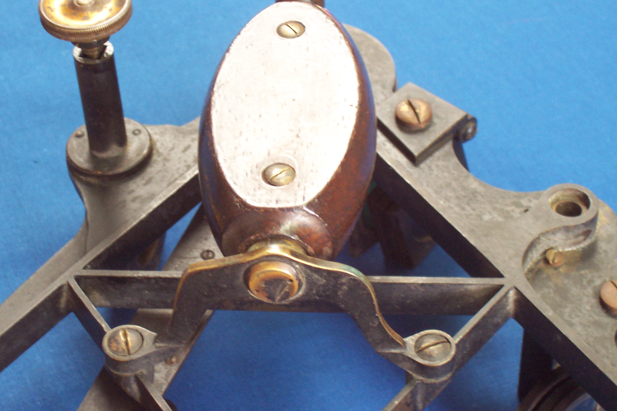
As so far described, the index arm showed no change for as long as vernier sextants were produced. This sextant is slightly unusual (but not unique for the period) in that the vernier scale is attached to the upper side of the window in the expansion. At the upper end, however, the index mirror is not attached directly to the index arm. Instead there is an intermediate turntable which rotates on an extension of the bearing shaft and is secured to it by a screw that sits in a counterbore in the turntable. At the top end of the turntable is a lug which allows small adjustments to be made to the position of the turntable to which the index mirror is attached. In short, it is a rather elaborate method of adjusting out index error. The next three figures may make this clearer.

Fig 7 Turntable bearing

Fig 8 Turntable adjustment

Fig 9 Index mirror mounting

The index mirror is mounted in a way that became pefectly standard and is probably due to Peter Dolland. In a letter that he wrote to Neil Maskelyne, the Astronomer Royal in 1772, he wrote “…I have contrived the frame, so that the glass lies on three points, and the part that presses against the front of the glass has also three points exactly opposite the former.”The method of rotating the index mirror on a turntable may be what is referred to by the words “Kings patent” on the limb, granted to Peter Dollond in May 1772 for ” …adjusting and improving the glasses of Hadley’s…sextant…”    . It is possible that it refers as well to the method of adjusting the horizon mirror for side error, about which more later.

Figure 10 Broken journal

As I have already mentioned, the index arm bearing was entirely conventional, but on removing the cover, I found some “repairs” had been carried out:  someone had broken the head off the original screw and crudely replaced it with a modern self-tapping screw. On further dismantling , the Araldite  that had been used in the “repair” to attach the shaft to the flange that marries it to the index arm gave way. You see the result in Figure 10. I had to attach a new piece of brass to the flange (Figure 11), taking great care to maintain squareness and then turn the  journal to match the existing taper of an included angle of about 0.8 degrees (Figure 12). Those interested can Contact me to find out how I set up the lathe to cut this rather fine taper. I then milled the square on the end of the shaft (Figure 13). This is easily and precisely done with modern machinery, but the eighteenth century instrument mechanic would have used a file and filing rest to do the same job and probably in much less time than it takes me to set up the machine.

Fig 11 Journal repair 1

Fig 12 Journal repair 2

Fig 13 Journal repair 3

Generally, I would strongly advise repairers against removing the bearing from the frame, but in this instance, the rear end of the bearing had been damaged during the original “repair” so it had to be faced off in the lathe. It was inserted from the back and was a very tight push fit, so to maintain the original centring I had only to replace it in the same orientation as it was originally, paying great attention to cleanliness. Removing it also gave me the opportunity to observe traces of black lacquer hidden beneath it, thus confirming me in the view that these instruments were supplied as painted workaday instruments and not as shiny display pieces.
Design of the tangent screw and clamp was standard for the day and again remained unchanged until the demise of the vernier sextant (Figure 14). The leaf spring would have been made of a thin sheet of brass, “well-hammered” to work harden it and make it springy. I took a short cut and used a piece of modern hard brass, first sweating it to the clamp, before drilling and tapping new holes for two screws. Note that the tangent screw knob slides on a  square on the end of the screw, the standard method of the day to remove backlash at the bearing, though no provision was made to remove it at the bronze nut as well.

Fig 14 Tangent screw and clamp

There is nothing unusual about the mounting of the shades, except that all the washers are free to rotate on the tapered shafts, while later designs adopt some means to stop them rotating, so that when one shade is rotated into place, the movement is not transmitted to the adjacent ones. The design of the rising piece is also unremarkable for the time and was followed with various more-or-less complicated minor modifications until the mid 1950s.

This leaves the horizon mirror and its mounting. Peter Dollond’s patent of 1772 (number 1017) mentions improvements to mirror mountings. In a letter of the same year to Nevil Maskelyne he writes: “To adjust the horizon glasses in the perpendicular plane of the instrument, I have contrived to move each of them (there was also a “back horizon glass” that soon fell into disuse with the increasing popularity of the sextant) by a single screw, that goes through the frame of the quadrant, and is turned by means of a milled head at the back, which may be done by the observer while he is looking at the object.” His letter also makes plain that horizon shades were an innovation devised by Maskelyne.

The next photo (Figure 15) shows the arrangement in place. The screw passes through the frame into a tapped hole in the base of the mirror mounting and is used to tilt the horizon mirror in such a way as to remove side error, as index error has been taken care of by the index turntable, but note also that there is a capstan headed screw which can also deal with index error. Perhaps it was a later addition, the index turntable having been found wanting.

Fig 15 Dollond's adjusting screw 1

Although Dollond gives no details, the hole through the frame of the sextant is much larger than required for the screw alone, and I surmise that there must have been a helical spring to take up backlash at each end of the screw. However, the screw is threaded almost to the milled head and it is possible there may have been some sort of locknut arrangement to hold the screw captive, since lost. While the spring seems to be obvious solution, there are other possible simplifications to the design of this sextant that also seem obvious to us in the light of two centuries of hindsight, but which plainly were not so to the instrument makers of the late eighteenth century. Figures 16 and 17 make clear the design of this curiously complicated solution.

Fig 16 Dollond's adjusting screw 2

Fig 17 Dollond's adjusting screw 3

 While some museologists might regard it as heretical, I try to restore my instruments to the way they might have been when fairly new, perhaps just out of the instrument maker’s shop after an overhaul. This usually includes repainting with something as close to pre-modern paint as possible. Modern paint seems to be much too thick and I use a black lacquer, which gives a very pleasing finish. Most of the screw heads would have been polished and their slots cleaned out, following clock-making practice. I will allow that the telescopes were probably polished rather than painted. The next two pictures show the finished instrument from front and back. These imges will withstand considerable enlargement if you wish to see more detail.

Fig 18 Finished, front

Fig 19 Finished, rear

Both Figs 18 and 19 show the outside of the case, which was in quite good condition and responded well to fine sanding and a coat of wax. One of the hooks and its eye were missing, and their holes had been closed off with pink car body filler. I made fairly close copies of the hook and eye by sawing and filing them out of plate brass, and think they will pass at least casual inspection. I made the octagonal handle out of a piece of unidentified New Zealand hardwood, stained and polished, and let in a piece of brass rod, threaded to fit the hole in the back of the handle, I secured it in the handle with a transverse piece of brass rod. Used as we are to hexagonal nuts and bolts, we might wonder why handles of this type were octagonal. I suggest that it is firstly easier to make, by planing off the corners of a square, and secondly, while a hexagon is easily held in a three jaw self-centring chuck, such chucks had not come into use in the eighteenth century and if a turner possessed a chuck at all, it was likely to have four independent jaws, better adapted to holding an octagon than a hexagon.

 The final picture shows the sextant in its case. The telescope is not without interest. It is a Galilean or “star scope” of about 3 power and with an objective lens of only 14 mm in diameter. Newton’s rings are clearly visible when looking at the objective, showing that it is an air-spaced achromatic lens, as lenses were not cemented until well into the nineteenth century. Its small size is probably because large pieces of good flint glass were hard to obtain. The eyepiece is threaded for an eyepiece shade, but there is no accommodation for one in the case.

The name of Dollond arises again in relation to achromatic objectives. John Dollond is often cited as the inventor of this type of lens, even though it is well established that Chester Moor Hall was making them for himself in 1729 and it was well known to the optical trade by the middle of the century. Nevertheless, John’s son Peter urged him to take out a patent and in this he was successful, against staunch opposition from about thirty of the leading London opticians. There is a link to Jesse Ramsden, the inventor of the first precision circular dividing engine. Ramsden is thought to have tried to put the record straight and he was in a good position to know it, as his wife was Peter Dollond’s sister. There is a space for an inverting telescope, which would have been about 140 mm long and of probably about 6 power.

The case itself is of mahogany and it is interesting to note that the bowed front is not a segment of a circle but its radius increases towards the right, so that the sextant will fit in the case only if the index arm is parked close to zero. This appears to be so of many early sextant cases and was presumably deliberate.

A question which will occur to some might be “How accurate is it?” This will have to wait for another time… (See Postscript no. 3)

Fig 20 Restored sextant in restored case

I hope this rather lengthy description of an old sextant will be of interest to lovers of fine instruments as well as contributing to the record of instrument making. I cover in detail the structure of sextants from about 1850 onwards in my book “The Nautical Sextant” , jointly published by Paradise Cay and Celestaire. Contact me if you would like to buy a copy directly from me (probably only worthwhile for New Zealand and Australian readers).

Postscript no. 1: It later occurred to me that platinum is harder than silver. On the Vickers scale of hardness, it is about twice as hard. I made a new business end for an automatic centre punch to give it an included angle of 135 degrees and set up the punch so that it delivered a constant blow when actuated. The size of the tiny punch mark made in the end of the scale was of the same size as that made in an arc known to be of silver. The conclusion is that the Gilbert arc is the same hardness as silver. If it looks like a duck…

Postscript no. 2: On careful examination  with magnification and the right light, a rivetted screw head is just visible in the brass at the left hand end of the arc. My surmise that a slip of brass was rivetted in after machining the groove for the silver arc seems to be correct.

Postscript no. 3: The errors are as follows:

Degrees                                Error, arcseconds

15                                                  +6

30                                                 +2

45                                                  -3

60                                               +10

75                                                 +6

90                                                 +3

105                                             +24

120                                             +25

See more details at http://www.fer3.com/arc/m2.aspx?i=113271


Troughton and Simms Surveying Sextant

28 04 2010

The preceding posts covers “A C19 Sextant Restoration” , “Making a Keystone Sextant Case” , “Restoring a C. Plath Drei Kreis Sextant” , “Heath Curve-bar sextant compared with Plath” and  “A Drowned Husun Three Circle Sextant” .

I recently acquired a Troughton and Simms sextant, with all its attachments, but without a case. I find I can sometimes afford such homeless sextants and, after having made ten cases, I can now make them so that they look reasonably in period. It was described in a later catalogue as a “Surveying Sextant, 7 ins., divided on silver and reading by vernier (with magnifier) to 10 secs. ..” In fact, it would also pass as a nautical sextant, as it is provided with the usual seven shades and kit of telescopes and sighting tube. The inverting scope, provided with four wires in the eyepiece,  is of 6 power with an effective aperture of 17.5 mm. The star telescopes are 2 power x 17 mm and 3 power x 15.5 mm. The latter may have belonged to another instrument, but both are in the same style.The Troughton brothers were active in London around about 1800. Edward Troughton (b.1765) carried on the business of instrument making after the death of his equally famous older brother, John, in 1788.  By 1824, getting on in years, he took into partnership William Simms (b. 1793), describing him to an acquaintance as “the best craftsman he knew.” Troughton died in 1835 and Simms in 1860, but the business carried on as Troughton and Simms until 1916, when it became a Limited Company. It merged with T Cooke and Sons of York in 1922, to become the  famous firm of instrument makers, Cooke, Troughton and Simms, with manufacturing being carried out in York, and offices and service centres in London and throughout the then British Empire.

Thus, my sextant is unlikely to be later than 1916, but is otherwise rather difficult to date. There are features like the handle and the index mirror mounting that would place it in the nineteenth century, while the horizon mirror frame is possibly a twentieth century replacement. The cast bronze frame is perhaps a little old-fashioned, while the maker’s name on the limb is in an elegant script, typical of the nineteenth century rather than later stamped typeface. There is little information to be had about serial numbers of this maker. A sextant numbered 1920 is reliably dated to 1836 and if we take forty instruments a year as a reasonable estimate of number made, my sextant would find itself in the last quarter of the nineteenth century. Troughton and Simms made very large numbers of surveying and other instruments during the expansion of the British Empire, and it is likely that sextants formed only a very small part of their output. The next picture shows it as I received it. 


The rising piece had a bend in it at the junction with the ring and the telescope ring was heavily corroded with more than a century of verdigris lurking in the crevices:

Plainly, the rising piece had broken the fall of a dropped instrument. In the next photograph, which also shows the handle, it can be seen that the lead screw has punched off the end of the rising piece body. This normally appears to be solid with the body, but is in fact a disc of brass soldered on to the end of the body, as it would not otherwise be possible to form the square hole. The leadscrew is normally held captive in the body, the disc being sandwiched between a flange on the leadscrew and the thumb screw.

In this instance, it was fortunate that the joint gave way, as the rising piece was jammed solidly in the body, and it would not otherwise have been possible to extract the leadscrew. Once it was removed, I could press out the rising piece in the vice:

Once I had the rising piece out of the body and separated from the telescope ring, I could straighten it using a straight edge as a datum, so that it could once again slide smoothly up and down without any shake. Note that there are two recesses machined into the stem of the rising piece for a pair of leaf springs. These I imagine were fitted to help reduce shake, but the mechanism functions perfectly well without them. The thumb screw had still to be parted from the leadscrew. This required only a well-fitting screwdriver and some brute force. I could then clean up the disc and resolder it to the body.

The rest of the restoration simply involved dismantling and cleaning all the parts, followed by fresh coats of black lacquer to the frame and other parts. Then I had to make a case with dovetailed corners and pockets for the various ‘scopes and tools:

I carved the hook latches out sheet brass and had to make the round-headed screws with which they engage, as none of  the round headed screws I could find on sale had plain slots. The handle is a drawer pull, which I have provided with a finger plate. I hope the handle  does not look too out of place:

The next photos show the maker’s  name on the limb…

The structure of the handle is practically unchanged from one from the 1820s. Note the tablet shaped wooden handle, the elegant lower bracket and the way the handle is attached to it with a pin screw. These screws, with two pin holes for a pin wrench were found aplenty in the Troughton Brothers’ famous pillar sextants of the late eigtheenth and early nineteenth century. In these sextants, the frame was formed from two plates about 1.5 mm thick, held apart by about a dozen pillars, to which they were secured by pin screws. Imitating clock-making practice, this gives a relatively rigid and light-weight structure, but was very expensive to make.

As one might expect from a maker whose principal products were surveying instruments, the tangent screw mechanism follows theodolite practice. A block that can slide in guides on the back of the lower end of the index arm can be clamped to the limb. A tongue projects from the sliding block and is sandwiched between the end of the tangent screw and an opposing spring, both of which are contained in a tubular frame that is secured to the lower end of the index arm. When the clamp is released, the index arm is free to move over the arc. When it is secured to the limb by the clamp, the tangent screw can be used to make fine adjustments and the spring inside the spring box takes care of backlash, which can be an annoyance in a vernier instrument, even though it does not affect the accuracy of the reading. The next photo shows these details in the un-restored instrument:

Edward Troughton originated a dividing engine to rival that of his famous near-contemporary, Jesse Ramsden and described it in the Proceedings of the Royal Society for 1805. With a sextant coming from this background I  expected the dividing of the arc and vernier to be of a hight standard and I was not disappointed, as the next photo shows:

(In this and other pictures, you can enlarge them to see more detail by clicking on the picture. Return to the post by clicking on the back arrow.)

Finally, a picture to illustrate the archaic index mirror adjustment. The mirror is held against an angle bracket by a keeper and screw. The bracket is held to the top end of the index arm by two screws and can pivot about two pins adjacent to the screws. A third, adjusting  screw rocks the whole bracket.

If you enjoy reading about details of fine instruments, you will enjoy my forthcoming book The Nautical Sextant. You will find some details about it in “About the Book.” Contact me via this site if you would like to be informed when the book goes on sale.


A Drowned Husun Three Circle Sextant

18 02 2010

The preceding posts covers “A C19 Sextant Restoration” , “Making a Keystone Sextant Case” , “Restoring a C. Plath Drei Kreis Sextant” and “Heath Curve-bar sextant compared with Plath” .

Some good friends came for the weekend about ten days ago and one of them presented me with a wooden box that rattled ominously. An old uncle had been clearing out his house and had asked her to find a good home for the box and its contents. I recognised the box as belonging to a Hughes and Son sextant from the placing of the hook latches so that gravity keeps them both in place when the box is being carried, and on opening it, this is more or less what I found inside:

Figure 1 : Sextant as received.

As you can see, the key hole of the case is plugged with mud and some of the smaller parts inside were also encrusted with it. Most of the paint had disappeared from the frame and index arm and all the woodwork was loose, but there was no obvious major damage to the individual parts. In particular, the arc was all in one plane, the index arm was not bent and the index arm bearing was in good condition. All the screws, both great and small were present, but the lamp and its mounting for illuminating the scale were not and the electrical parts of the battery handle were the worse for wear. Of the wiring there was no sign.

This is the third valuable sextant I have been presented with as a gift and I count myself very fortunate to have such friends. I foresaw hours of pleasure ahead of me, though with some tedium involved in polishing screw heads and cleaning parts.

I began with the frame and index arm. The release catch was still attached to the latter, so I removed the parts and also removed the legs from the frame to make the clean-up easier. I left the index arm bearing in place and in general, this should never be removed, though in this instance, as there was no inspection certificate, there would have been no great harm in removing the bearing and re-calibrating the sextant. However, it would have required a special ring spanner and it seemed pointless to make one for an unnecessary task.  There is no harm in removing the tapered “journal” from the index arm, but it is seldom necessary to do so unless there is heavy corrosion around it.

I gave the parts a prelimary soak in diluted household ammonia, rinsed and then stripped off the remaining paint with a proprietary paint stripper. I then brushed all the mud and verdigris from the teeth of the rack, dried everything off and hung the frame and index arm up for repainting.

Hughes and Son at this time (1938) used a wrinkle finish paint on these parts, with a black lacquer for most of the others. The advantage of such paint is that it hides any minor blemishes in the finish of the underlying metal, it is not distractingly glossy and, having been baked on, it is reasonably tough. However, it had not withstood immersion in sea water very well. Happily, modern paint technology allows us to get the same finish without baking. I use PJH brand “VHT Wrinkle Plus” spray paint and find it gives a very good result. The wrinkles can be made tighter by heating with a hot air gun as the paint begins to dry and before the wrinkles have started to form. The next picture shows the finish I obtained, and it is quite close to the original (I have other Hughes sextants with which to compare it).

Figure 2 : Wrinkle finish paint.

Although the wrinkle paint appears to dry quickly, it is very easy to damage it, and, as a full cure takes five days, I moved on to some parts that I knew would take care and time to restore: the shades assemblies. I started with the easier horizon shades. These are mounted on to a bracket by means of a shouldered screw and locknut and separated from each other by washers. The washers have integral keys that engage with a keyway on the screw so that they cannot rotate. This ensures that when one shade is rotated, the others do not follow. Some resistance is applied by means of a Belleville washer, a dome-shaped washer that behaves as a short, stiff spring. You will see from the next photograph that the Belleville washer had not survived.

Figure 3 : Unrestored horizon shades

The index shades assembly uses a much older system. The shades and their separating washers together form a tapered hole. A tapered pin passes through the mounting bracket and  through the shades and washers, which must therefore be assembled the correct way around and in the correct order. An adjusting screw forces the pin further into the composite hole to adjust resistance to rotation. The tapered pin is prevented from rotating in the bracket by means of a cross pin. Any attempts to remove the tapered pin without first removing this cross pin are doomed to failure, so look for it carefully and punch it out. There are other ways to prevent rotation of the pin and I cover these in my book. Once the cross pin has been removed, brute force in the shape of a wooden drift and press or hammer may be needed to force the tapered pin free. The next photo shows the result.

Figure 4 : Unrestored index shades

If you cannot obtain a replacement Belleville washer, and living where I do, I cannot obtain most things, one can be made. I turned a washer from a scrap of phosphor-bronze bar, sat a scrap ball bearing in the hole, placed the two over a larger hole in a steel block and hit the ball with a hammer. It may sound crude, but it works.

As most of the paint had deteriorated to a mixture of paint and verdigris, I completed the destruction with wet  emery paper prior to repainting. In the past, I have done the painting by hand, but as spray painting gives a much better appearance, I worked out a simple way to mask the glass, one that does not attempt the near-impossible of punching out large discs of masking tape. The next photo shows the steps. The knife has to be sharp and have a fine point to be able to follow the curves.

Figure 5 : Masking shades.

If the shades are then suspended from a bar that just fits through the mounting holes, they can be sprayed with black lacquer without too much of it getting into the holes.

There are some tricks to remounting the index shades. It is best to have a trial mounting on the pin, to make sure that you have the shades and washers in the correct order and the right way around. The cross pin is not usually exactly on a diameter and will usually fit only one way round, so make some sort of mark on the head of the tapered pin and bracket to indicate the correct orientation. Then lay the parts in order  on the bench while you grease the tapered pin and place a tiny dab of grease on each face of the washers. You can then reassemble them on the pin and remove the pin without everything dropping apart. With the shades and washers on the pin, wangle them between the cheeks of the bracket (the right way around, of course). Once they are partially engaged with the bracket, you can withdraw the pin and carefully engage them further until the narrow end of the pin can be re-entered through the bracket, waggling the shades a little so that the pin passes deeper and deeper into the composite tapered hole. Make sure the cross hole lines up correctly and then press the head of the tapered pin home. Insert the cross pin, adjust the adjusting screw and you are home.

Much of the rest of restoring this sextant consisted simply in cleaning and repaint parts, so for much of the rest of this post I will illustrate, usually without commentary, parts that differ in Husun sextants from other makes. A lot of the ground is traversed in my book, together with details of other manufacturers’ approaches.

For example, the telescope mounting:

Figure 6 : Telescope in situ

Figure 7 : Detail of telescope mounting.

The micrometer mechanism:

Figure 8 : Micrometer mechanism and rack.

The battery switch:

Figure 9a : Switch button.

Figure 9b : Switch exploded.

The wire passes through an internal passage drilled in the handle and leaves it via a plastic grommet on the left-hand side of the handle. Thence it passes to the central contact of the lamp bulb. The plunger of the switch makes contact with a brass disc which forms the top of the battery compartment. Both sides of the disc need to be clean for the system to work. Earth return is from the lamp mounting to the frame. The spring in the bottom of the battery compartment is attached to the  lid of the compartment. The lid is connected through its hinge to the bottom handle mounting and thence to the frame. A slender spring-latch, not electrically connected to anything, holds the lid closed.

Figure 10 : Battery compartment lid.

The next photo shows the connections at the lamp. I have only partly followed Hughes’ design. Mine is simpler, as it omits an insulating bush which is not really needed, as the wire itself is well insulated.

Figure 11 : Lamp mount exploded.

But first I had to make a new lamp-holder, shade and mounting. A hollow pillar is attached to the index arm expansion by means of a 4 BA countersunk screw. The other end of the pillar is drilled to accept a spigot on one end of the mounting arm and split so that it grips the spigot. The lamp shade is mounted at the other end of the arm. The shade is threaded to take a standard torch bulb at one end and, at the other, the threaded cap through which the wire passes. To change the bulb, the shade and its mounting arm is simply withdrawn from the pillar to allow access to the underside of the shade.

Making the pillar is a fairly simple turning , drilling and tapping exercise:

Figure 12 : Turning lamp pillar.

So is the outside of the shade:

Figure 13 : Turning outside of shade.

Boring the inside of the shade is a little more difficult. As for  all boring operations, it is harder to see and to measure what you are doing:

Figure 14 : Boring inside of shade

Do not expect to be able to buy a tap to cut the internal thread, at least, not for any reasonable price. It is 14 threads per inch x about 0.38 inches major diameter, with a rounded thread form. Most people will attempt to cut it on a lathe, which is how I did it. I sometimes help out new friends who extravagantly praise my work.

Figure 15 : Internal thread of lamp shade

I have covered making things like cutting out connecting arms in  previous posts. Here is a reminder:

Figure 16 :Tools for cutting out arm.

The completed lamp mounting, together with wire and new retaining clips shows up well in this picture of the completed sextant:

Figure 17 : Sextant restoration complete.

After its near-death experience, I felt that the sextant should have a decent home, and so I gave the box  some attention. The base had a very large shrinkage crack in it, so I removed it, whereupon the rest of the bottom half of the box began to fall apart and had to be re-glued. I planed the edges of the crack straight and square, and glued in a strip of mahogany, which can just be seen in the final photograph. The front had also shrunk a little so that the lock no longer fitted, and this required some attention with a wood chisel. The lock had at some stage been forced, leaving a large chip and the ends of no fewer than three broken screws in one hole, in the rebate in the lid where the hasp had been. I made a fresh start at the damaged area and glued in a new block of wood before re-fitting the hasp.

Like many households, we have a large bunch of keys that fit nothing in particular, but I found one that nearly fitted the keyhole, so after washing out the lock and oiling it, I filed away at the key  with the aid of marking blue to guide me, until it operated the lock. The various mounting blocks had to be screwed and glued into place and the felts of course had to be replaced. Aftere cleaning of the brass “furniture” and making a new adjusting pick, here is the final result:

Figure 18 : Restored case.

If you would like information or advice about some detail that I have not fully covered, contact me and I will try to help.


Heath Curve-bar sextant compared with Plath

28 01 2010

The preceding posts covers “A C19 Sextant Restoration” , “Making a Keystone Sextant Case” and “Restoring a C. Plath Drei Kreis Sextant” .

Shortly after I completed the restoration of a Plath Drei Kreis (three circle) sextant I was given the opportunity to restore an English sextant from the same period, a Heath Curve-bar sextant, so called because the frame appears to be made up of thin, curved bars (but is in fact a bronze casting). This one received a certificate from Kew Observatory in 1898 and in addition to being named “Heath and Co., Ltd.,  Crayford, London S.E.” also carried the owner’s name in full engraved in on the limb. As was usual in 19th century instruments, the maker’s name was in copperplate script rather than in the later type.

Like the Drei Kreis, the arc is divided to read to 10 seconds with the vernier and the radius of the arc is much the same at about 165 mm.

Apart from there being widespread verdigris, this sextant posed no particular problems as everything was intact, with no missing parts, so I will not bore you with the details of restoration. It was a simple matter of dismantling it to its parts, cleaning off verdigris, polishing screw heads and re-lacquering. The case needed only filling of a large shrinkage crack in the bottom and cleaning up the handle and latches. Unfortunately, at some time the arc had been polished, so the divisions are in places rather hard to read. While some nineteenth century sextants were chemically blackened, I found traces of black lacquer on the little caps that cover the adjusting screws. The next photo shows the instrument cleaned and reassembled while I waited for the owner’s instructions about re-lacquering. 

This photo shows the finished article:


 I thought this an ideal opportunity to compare an English with a German vernier sextant of approximately the same period, at the turn of the twentieth century.

In the preceding post I mentioned the complication of the tangent screw mechanism in the German sextant. In the Heath instrument, it is perfectly conventional and typical of a mechanism that seems to have served makers and navigators well for over a hundred years.

In the photo above, the sliding block moves in a curved slide formed by a cut-out in the index arm expansion. The floor of the slide is formed, as in the German sextant,  by a plate that is screwed on to the front of the index arm. The end of the clamp screw bears on a small plate to which is attached the clamp leaf spring. The tangent screw is held captive on the index arm by a bearing. The tangent screw has the familiar squared end, and the knurled knob is attached over the square by a central screw which allows the bearing to be adjusted to remove end play. The squared end prevents rotational forces from being applied to loosen the screw. The sliding block is held against the floor of the slide by a leaf spring, seen in the next photo, of the front of the index arm expansion. The screw that passes through the leaf spring holds the nut on to the sliding block. This spring has the same function as the leaf spring on the rear of the sliding block of the German instrument.

The nut is split. This allows the nut to spring inwards and to grip the tangent screw thread flexibly and remove lost motion between the screw and the nut. When the clamp is tightened, the sliding block is held immobile on the limb and when the tangent screw is turned, the index arm is caused to move via the screw bearing.

While the German arrangement is free from backlash when in good adjustment, if there is any stickiness in the slide, it has the annoying feature of moving in one direction, but not returning by means of the spring pressure. In the other arrangement, if the fit between the tangent screw and the nut is not good, due, say, to wear in the screw, or if the bearing is out of adjustment, then there is backlash in both directions. In both types, if the slide is sticky, movement may be uncertain and jerky. In my view, each defect is as bad as the other, but the English mechanism has the merit of simplicity.

In every edition of his work “Wrinkles in Practical Navigation” (and it ran to 21 editions ) Captain Squire Thornton Lecky wrote “An indispensable condition in a sextant is regidity; flexure is fatal…”, so I thought to make a quick comparison of the two sextants, using the crude set up shown in the next photo. The middle 100 mm of the limb is held clamped firmly in a vice and a dial  indicator, reading in 100ths of a millimetre bears against the end of the index arm bearing. A force of one kilogramme is applied to the index mirror by means of an old  kitchen scale and the amount of deflection read off the dial indicator.

Though the German sextant at 1.5 kg weighed about 250 G  more than the English one, there was little difference in the amount of deflection, about 0.6 mm. Interestingly, two mid-nineteenth century English quadrants of radii 20 mm greater and of about the same weight, deflected significantly less at 0.5 mm for a Spencer, Browning and Co., and 0.4 mm for a Crichton. Late twentieth century die-cast aluminium alloy instruments typically deflected about 0.12 to 0.15 mm in this set-up and bronze-framed ones somewhat more. Allowance must of course be made for the smaller radii of the modern instruments, but even so, the superior rigidity of alloy instruments is clear. Neverthless, right to the end some buyers expressed a preference for the heavier, more expensive but less rigid bronze instruments.


Restoring a C. Plath Drei Kreis sextant

24 01 2010

The preceding posts covers “A C19 Sextant Restoration” and “Making a Keystone Sextant Case”

On Christmas Eve of 1974, The small city of Darwin in Northern Australia was struck by Cyclone Tracy, a very compact and intense cyclone with winds gusting to well over 220 kph (140 mph). Eighty percent of the houses in Darwin were totally destroyed. One of the casualties of the destruction was a sextant that in the aftermath found its way into a trunk with several other sextants and theodolites. The trunk was sold at auction for $20, the sextant was passed to a neighbour, a retired merchant sea captain, and he in turn recently passed it on to me. Such generosity must be very rare.

The sextant had escaped major damage. Though some screws were bent or missing, they could easily be repaired or replaced. Mild corrrosion with verdigris was  present, but the frame and index arm had been carefully cleaned without polishing the arc, which was in good condition. Fortunately, in the bottom of the trunk were a sighting tube and  two telescopes. The inverting ‘scope was missing  the objective lens, but my friend in Darwin went back to his neighbour’s trunk and found it in a corner. It was intact, but the balsam between the two parts of the achromatic lens had perished and the lens was unusable in that state. Apparently, it was this that had saved it from being converted into an air-rifle sight.

The next picture shows the sextant as I received it. The bottom screw that attaches the handle was missing and the clamp screw was bent. The lacquer on the telescope tubes had deteriorated to a powdery and patchy brown and the draw tube of the inverting telescope had seized completely. The clamp spring was absent and one of the dowel pins that held it in place was damaged. One of the legs had been replaced by an odd leg. The ground glass diffuser screen above the vernier scale had disappeared. There was, of course, no case, so I felt very lucky to have a complete kit of telescopes and sighting tube.

The famous name “C Plath, Hamburg” was clearly visible on the middle of the limb, and after a little cleaning of the bronze at the right hand end I found  the original tiny Plath logo of a little stick man with a sextant. The “S” is the inspection mark of “Seewarte” or naval observatory. Later, this became “D.S.” for “Deutsche Seewarte” or German Naval Observatory, some time after the formation of the German state in 1871.

Less easy to see was the serial number 5499 on the silver of the arc. The arc is divided from  – 5 to +157 degrees, but the scale is usable up to only 138 degrees 30 minutes,  so that although it was sold as the Drei Kreis (“three circle”) quintant, it falls a few degrees short of 144. The serial number places it a little before 1910 in date, on the basis that Plath made an average of about 320 sextants a year between 1910 and 1925.  The arc of about 175 mm radius is divided to 10 minutes, with the vernier allowing reading to 10 seconds, in principle if not perhaps in practice. Apart from the rather complex tangent screw mechanism, the construction of the sextant is perfectly conventional.  The next photo shows the rear view of the sextant as received.

The next step was to dismantle the instrument to its component parts, clean them in a solution of 50 percent household ammonia with washing up liquid added, rinse, dry and apply masking tape as in the next photo, prior to spraying them with black lacquer.  Although antique sextants are often found with all paint removed and the “brass”  (in fact, bronze) polished to a shine, they were never sold this way. Most often they were painted or lacquered black, or, with earlier ones, chemically browned or blackened. If the silver scale is unreadable owing to tarnish, it usually yields to the diluted ammonia and gentle rubbing with the pad of a thumb. On no account should it be polished, as the markings are very shallow and can be obliterated completely by vigorous polishing. I have one 1920s sextant in which only the numerals remain and am currently restoring one in which the markings over about 20 degrees of the scale are very faint.

Here are the parts looking distinctly refreshed.

I had to make a new leg and this slightly un-sharp photo shows the turning in progress to make the rather slender, tapered leg. Once parted off, a thread then had to be cut on the wider end. Fortunately, all the threads are metric ones.

Although the threads are standard, some of the screw heads are not, so I had to make a new screw to attach the handle. This photo shows it being parted off from the parent 12 mm brass bar.

The clamp screw was bent, but I was able to persuade it back to straightness. The tangent screw mechanism is rather complicated when compared to the standard nineteenth and early twentieth century arrangement, and I hope the next two photographs will help to make its workings clearer. It came into my hands just too late to be included in the print edition of my book, now in preparation.

The clamp is a thin slab of brass that is retained in the sliding block by two dowel pins that allow it some up and down movement, opposed by the leaf spring (ground to shape from a piece of clock spring and soft soldered to the clamp). The clamp screw locks it and the sliding block to the lower edge of the limb. The sliding block is hollow and contains a strong helical spring and its guide, the latter projecting from one end of the block. The other end is split and tapped for the tangent screw. A tongue, which is attached to the underside of the index arm expansion by a screw, is sandwiched between the tip of the tangent screw and a bronze block on the end of the guide. Two screws can be tightened to close the split in the sliding block a little, to ensure a snug fit of the tangent screw.  The sliding block is guided by two curved edges machined in the index arm expansion and is prevented from lifting away from these edges and the underlying surface by the sliding block spring, itself attached to an elbow bracket.

When the clamp screw is tightened, the sliding block is locked to the limb and when the tangent screw is tightened, it moves the tongue and the index arm to which it is attached. When it is slackened, the helical spring moves the index arm in the opposite direction. The two screws that are intended to remove backlash (lost motion) from the tangent screw are unnecessary because the opposition from the helical spring does this. They were a nuisance as far as I was concerned because they both lost their heads when I was trying to remove them and needed about half an hour’s work to drill them out and re-tap forslightly larger screws, which I  had to make from scratch. When a spring-opposed mechanism like this works, it is a pleasure to use, but dirt or a breakdown in lubrication can easily cause it to fail to return in one direction, and this is very annoying.

The rise and fall mechanism for the telescope is conventional:

Having overcome these various obstacles, it was time to reassemble the instrument and adjust the mirrors to ensure they were square to the plane of the arc and, when the scale reads zero, that they were parallel to each other. The paintwork is not quite as shiny as this flash photograph seems to suggest.

This still left the inverting telescope, with its seized draw tube and damaged objective lens. I tried various combinations of spirituous chemicals, releasing compound, heat and cold, but could not persuade the rather thin-walled tubes to release their grip on each other. Vigorous twisting was of course out of the question. In the end, I removed all the optics, pressed out the various light stops and machined a steel slug that fitted snuggly in the wider tube. I then used my larger lathe as a press jack to push out the narrower tube. In the next photograph, the tube is held loosely in the chuck against the shoulder and the steel rod held in the drill chuck is being pressed against the slug, which is out of sight inside the tube. It worked like magic.

The objective lens was even more of a problem, as it was swaged into a little brass cell. Swaging means that a lip of metal is bent over the lens to hold it in a recess in the mounting, and often the only way to get the lens out is to somehow hold the mounting in the lathe and carefully turn away the swaged metal. I managed to do this with only minimal damage to the edge of the lens, and still had enough of the mounting left to make replacement possible. Replacement lenses of the correct focal length and diameter are very hard to come by, so this was a relief.  Once the lens was out, I heated it slowly in a pan of water and, just short of boiling point, was able to slip the two components apart. A little xylene, in which Canada balsam is soluble, cleaned up the two part-lenses and I recemented them with Ultra Clear Araldite, rather than the now-obsolete Canada balsam or one of its very expensive modern replacements. I also used a tiny smear of the same adhesive to remount the lens in its cell. The telescope now gives a very clear view. The next photo shows the rear view of the sextant with restored telescopes, new adjusting pick and a tiny screw driver made from scraps of silver steel, brass and mahogany. The brush is C19 English, but does not seem out of place with this German instrument.

Some woodwork came next. Although I am slow at making dovetails, I can now do so without disaster. The sextant was supplied originally in a box with machine-made comb corner joints, but dovetails with narrow pins are also in period. These can just be seen in the next photo, which shows the interior fittings too. The wood is Sapele (Entandrophragma cylindricum), an African hardwood that closely resembles mahogany.

The photo following shows the instrument and its accessories in place:

The final photograph shows the exterior of the case. I don’t know what contemporary latches and handles would have looked like, so have copied English hook latches of the same period and made a handle that I hope looks slightly Germanic. It is made of five pieces of 6 mm  brass rod silver soldered into a whole. I used French polish for the final finish. I can recommend Zinsser Bulls Eye French polish. It is easy and quick to apply, and an amateur like me can get a good finish with it.

Do let me know if you would like more details of this or any other sextant I have covered on this blog.

If you have enjoyed this post, you might enjoy my book, now in print and available from the publishers or through amazon.com


Making a Keystone Sextant Case

17 12 2009


The preceding post covers “A C19 Sextant Restoration”

Looking around me at my collection of nautical sextants I see that about forty percent of them came to me as homeless refugees from the internet. Eight now have cases with dovetailed corners and two with rebated and pinned corners. Recently, I attempted to reproduce a keystone case, that is to say, one that looks as if it has been cut as a wedge from a round cheese. Two problems distinguished the task from the making of a square case: making the bowed front of the case and cutting dovetails with narrow pins at angles other than 90 degrees.

Seven cases with four corners each amounts to a lot of practice at cutting dovetails, so I felt that I could overcome the second problem relatively easily. Everything hinged on making the bowed front, so I tried that first. I had a ninetenth century case as a model to guide me and the thickness of its walls is about 8 mm. A plank of that thickness, 150 mm wide and 350 mm long cannot be bent easily, but some guidance from the internet suggested I had only to steam it and it would be as putty in my hands. It wasn’t. Half an hour steaming in an improvised steamer resulted in warping of the wood, but bend it would not.

Having a 50 mm plank of Sapele (an African wood similar to mahogany) reduced to three 10 mm planks had left me with some of only 2.6 mm thick, so I tried steaming these and then clamping them in a mould while they cooled down. The mould is made from slices of thick tri-board board cut to (nearly) the same shape and glued together, with aluminium foil glued to the surfaces to protect them from the steam and water. It took quite a while to smooth the large concave surface to shape with a spokeshave, so long in fact that I contemplated buying a compass plane – until I discovered the price. The convex surface was large enough to make attack with a bench plane quite feasible.

The thinner wood was much more amenable to steaming and bending, but it didn’t stay very bent on removal from the mould, though it did acquire interesting three dimensional shapes, combined with splits. My third attempt was much more successful. I simply applied glue to the boards, laminated them and squeezed them to shape in the mould. Once the glue had dried, there was only minimal “spring back”. Once I had planed the edges, it was not possible to say that the proto-front had begun as three pieces.

I did not anticipate much trouble with the front dovetails as, except for the spring-back, the angles were about 90 degrees. However, I had never made any with the traditional narrow pins (the bits that fit between the tails). I don’t know why the pins were made narrow, rather than about equal in width to the tails. They do seem to be more elegant, but perhaps that is just a matter of taste.

This isn’t a woodwork site so I won’t describe how to make dovetails. There are several blogs that will give you a little video on how to cut dovetails. Usually, the demonstrator shows how to mark out and then makes rapid saw cuts that miraculously result in joints that instantly fit together perfectly and without any need to pare with a chisel. I do need to use a chisel, sometimes quite a lot, and sometimes I need a putting-on tool, something that does not exist in the engineering field but which in the woodworking  field is called mahogany paste. I find that it does help when marking out to use a marking knife for all cuts and then to cut out little 90 degree triangles into the waste wood using a chisel. They seem to help guide the saw and also provide a clear guide for the paring chisel that follows.

The rear corners are at an obtuse angle and I relied on my model case to give me the angles to mark out the dovetails. Sometimes my saw went a cut too far, but I was able to disguise this with mahogany paste after gluing the bits together. Clamping them cannot be done with any clamp that I possess, so I resorted to the old trick of using webbing. The blocks of scrap wood seen in the next photo serve the dual purpose of tightening the webbing as they are slid towards the corners as well as concentrating the clamping force near the corners. It is best to sit the carcase on a flat surface and “persuade ” it to sit flat before the glue dries. A sextant can be seen in the background, watching its new home being built.

I didn’t have any wood wide enough for the top and bottom of the case, so I glued pieces together edge to edge. When doing this, it is of no use to hope that glue will do the job without proper preparation. It is essential that the edges be both straight and square before rubbing them together with a layer of glue between and clamping them. It is I think  fair to say that the joint I made is invisible. Once formed and cut to shape I attached the top and bottom to the walls with glue and brass pins that were then punched below the surface, and the heads buried under mahogany paste. The next photo shows the new case in the rough, sitting atop its model.

The whole was now rigid enough to be put in the vice and the edges and corners finished by planing and sanding. It then had to be cut into two parts. I now use a hand saw for this and a Japanese dozuki saw is hard to beat. Those who have a bench saw might use this, but I have had one or two near disasters and now rely on the Mark I eyeball and hand. After dovetails, fitting hinges and producing the simple cut outs for the various pockets inside the case feels very easy. The sextant is looking very interested…

so in he jumps…

and closes the lid.

I finished the case by careful sanding, followed by a coat of red mahogany stain and wax. Given another hundred years of waxing and polishing, it should have acquired a beautiful patina. Now, if I ever sell this sextant, should I say that the case is not original? It is not exactly a fake, nor is it an exact copy. Is reproduction the correct word?

My comprehensive book on the nautical sextant has a chapter on cases, Christmas is coming and, as my grandchildren would say, I really, really need to buy a new sextant. Won’t you help me towards this goal by buying a copy of my e-book?*

* Now available only as a revised and extended print version (see Buy the book)


C19 sextant restoration

10 11 2009

Recently I returned home after a trip around the world during which I visited relatives in Britain, France and Texas. Shortly before setting out, I had secured a BU Ships Mark II sextant by Atlas Engineering of Chicago and while in Texas, I bought two more, a US Navy octant by Brandis and Sons, and a sextant from the nineteenth century. I am now busy restoring the instruments to good order, starting with the oldest.

 It has a bronze tulip pattern frame and, although it has no name, Spencer, Browning and Co (formerly Spencer Browning and Rust) made very similar or identical sextants in about 1840 to 50. As in the twentieth century, many of the component parts were standard and appear on sextants by various makers. The real heart of the sextant is its frame and divided scale and we know that these too were made by only a few makers, perhaps no more than ten in the whole of nineteenth century Britain. Thus, it is certain that many of the dozens of instrument makers whose names appears on sextants were in fact assemblers and finishers of parts made by others. We know that some makers actually did make most of the instrument and also that they were prepared to sell finished instruments for others to add their names.

As with so many old sextants, a previous owner had thought that polished bronze and brass looked better than whatever the maker had clothed it in, often black lacquer, but sometimes the bronze was chemically browned or blackened. In stripping it, it had probably been dipped in a bath of solvent. This treatment did not agree with the ivory main and vernier scales which had shrunk so that the main scale was loose and the vernier scale had cracked around the rivets which attached it to the index arm. Both had taken on a green tint.The ebony pear-shaped handle is intact apart from a fine crack, but at some stage the index arm clamp had been lost and replaced by a makeshift one fabricated from a 5/32 inch Whitworth screw and a disc of bronze. The scale magnifier had been similarly bodged together. The top part of the horizon mirror mounting was absent. The instrument was without a case.

I made a start with the angle base for the horizon mirror mount, which simply involved cutting a piece of heavy brass angle, filing it to size and shape, drilling holes in the right places and finishing the front of the angle to leave three tiny platforms opposite the tabs of the clip, yet to be made.

Copy of 100_3153

For the clip I first marked out what the finished object would look like unfolded and then cut it out of thin brass, using a jeweller’s piercing saw. The next picture shows the cut out piece in the rough state, before filing to size, bending into shape and soldering. A hole had first to be drilled for the threaded bush for the fixing screw, as it is easier to drill a small hole in thin brass when it is flat. Once the clip was bent into shape, the bush was rivetted on the inside.

100_3135

The magnifier called for some more work with the piercing saw, harder work this time, as the brass was thicker. To stay with the spirit of things, I used the front plate of a scrapped table clock. The next picture shows the cutting completed. As you can see, it is not the first time this plate has provided metal for a replacement part.

100_3147

As with any sawing, the closer you can keep to the line the less work there is to do to finish the part, but you also need to remember that putting-on tools are in short supply! With a little practice (quite a lot, really), it becomes easy to file to the lines. The secret with brass is to keep a set of files  that are not used on anything else. Use them on steel and they tend afterwards to skid uselessly over brass unless you use a lot a pressure, and then they tend to go where you don’t want them to go.

Once I had the outside filed to shape, I could put the part in the lathe to drill and bore the large hole to a size that fitted the outside diameter of a piece of thin walled tube from a scrapped Victorian something-or-other. If you haven’t got a lathe, this could at a pinch be done with piercing saw and files.

100_3148

I then glued the tubing in place. It would probably have been soft soldered in place in the nineteenth century, but I am not above using modern aids to fabrication. The lens was a scrapped field lens from an old microscope eyepiece. I had to make a piece of tubing for it and cut the 40 threads per inch internal thread using the lathe. The post also needed some attention, as the screw had been replaced by a soldered-in stud with a nut. I had to make a new washer, filing the square hole with a needle file. The washer fits over a squared section of the post and its purpose is to prevent rotational forces being transmitted to the screw and loosening it. The next picture shows the finished article with alongside it the monstrosity that it replaced.

100_3155

The new clamp screw was a fairly straightforward bit of turning and knurling, except for the thread which had to be 5/32 inch Whitworth. I went metric over twenty years ago and my odds and ends of Imperial screwing tackle do not include 5/32 x 32 tpi, so I had to screwcut it in the lathe. The clamp itself also needed attention, as it did not have a spring (and was the wrong size and shape anyway). I filed it to a somewhat better shape and made a new spring by hammering a sliver of sheet brass until it work-hardened and became springy, a trick that would have been well-known to C18 and C19 clockmakers. You can just see in the next picture traces of the solder that hold the spring to the clamp .

Copy of 100_3154

I was able successfully to glue one of the splits in the ivory of the vernier scale, but first I had to remove it. Traditionally, they seem to have always been rivetted into place, not a good practice, as the rivet inevitably expands a little in the hole and ivory tends to shrink as it dries out. Add a little corrosion and the stage is set for splits to develop. The rivets had rounded heads, so I made a little jig out of a stub of steel bar with a hole one end that just fitted over the head of the rivet with a through hole for a drill of the same (carefully measured) size as the shank of the rivet. Using the jig with a block of wood sawn to an angle of 20 degrees to support the index arm, I could drill through, confident that the drill would go through the centre of the rivet and cut off its head, without wandering. I elected to tap the resulting holes in the index arm 10 BA and to use screws to re-attach the repaired scale, partly because I have no tiny rivets, but mainly to avoid the very problem I was trying to cure. The next photo shows the finished result. You can see that the repair has been quite successful at the zero end.

Copy of 100_3160

I finished by stripping down the instrument to the last tiny screw, cleaning everything with an old toothbrush in a 50% solution of ammonia and washing up liquid, polishing the screw heads,  and painting the individual parts.

In the past, I have not been entirely happy with the appearance given by modern paints on antique instruments. Modern spray paints give a result that is almost too good and the paint film seems to be too thick. I mentioned this to an engineer friend when I called into his workshop to pick his brains about drilling out the rivets and he recommended a spray-on protective lacquer called CRC Black Zinc (also available in a variety of other colours). It sticks to bare metal without a primer, once cured it is tough and resists scratching and, best of all, gives an effect that pleases me. Take a look at the final appearance of the sextant and, as the TV shows say, you be the judge.

Copy of 100_3159

Once I have finished restoring the other sextants, I plan to try my hand at making  a wedge-shaped case out of my precious stock of African mahogany. If I make a mess of the bowed front, I will still have two sides to use in a square box.