This post was preceded by one on overhaul of the earlier Tamaya switches.
Early Tamaya sextant scale lighting systems used a switch that was obvious in action and simple to overhaul. Later ones used a fully moulded handle that had no obvious way of accessing the switch contacts, an essential requirement of an electrical system working in a salt water environment. I covered the older Tamaya switch in the previous post in this category and have also covered the even more mysterious structures of a couple of C Plath switches in the “Interesting Overhaul Problems” category. In response to a recent enquiry, I now give an account of later Tamaya systems.
If we begin with the battery handle and remove the screw cap from the bottom we are faced with a deep dark hole, but if the light is right, one can see a spring at the bottom, secured to something with a plated brass screw. The end of the spring is supposed to receive the negative pole of the battery and observant owners will have noticed that there is a “+” sign engraved into the inside of the screw cap. Undoing the screw at the bottom of the hole allows the switch button with attached parts to be removed and when this is deconstructed one can see its structure, as shown in Figure 1.

Figure 1 : Structure of switch exploded.
Note the contact screw that passes through a solder tag and a couple of washers into the sloping face at the upper end of the handle on the right. Figure 2 shows the parts assembled outside the handle. When the switch button is depressed, the end of the shouldered screw that passes through a bush and spring into the plastic button, moves to the right and makes contact with the end of the contact screw. We can now trace the current as it passes from the negative pole of the battery, through the spring and screw at the bottom of the hole, into the bush and switch contact and then into the contact screw on the side of the handle.
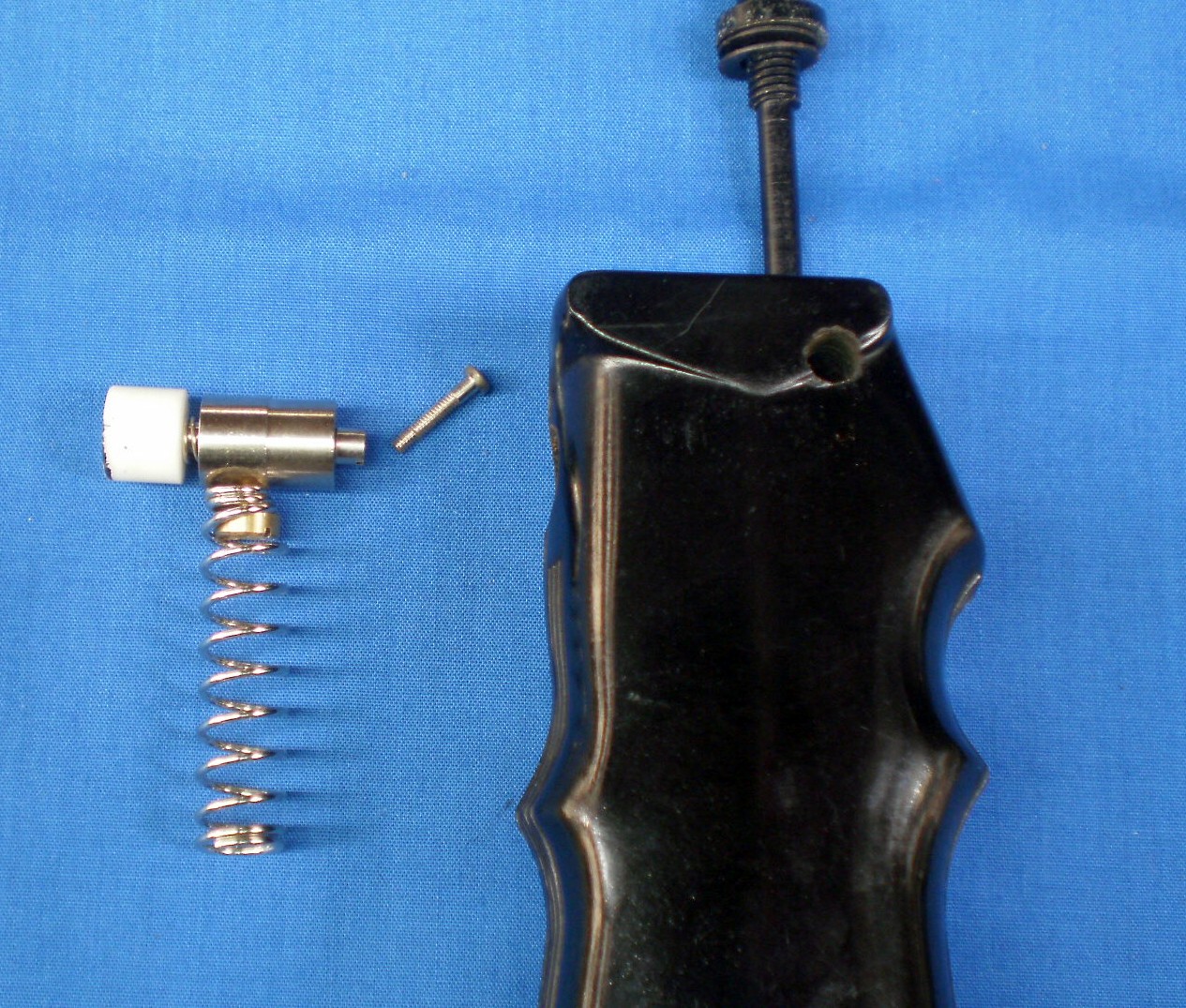
Figure 2 : Switch parts assembled outside handle.
The path of the wire that is attached to the solder tag in a Jupiter sextant is shown in Figure 3 . It is wrapped in a clove hitch around the upper leg of the handle to secure it and then passes through a hole in the index arm and under a rectangular cover on the front of the arm to the bulb. The path is similar in the Spica sextant but the bulb arrangement is different.
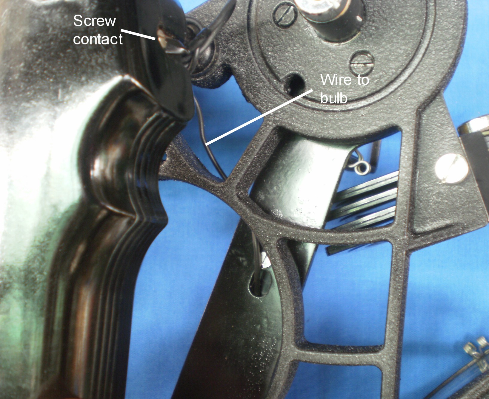
Figure 3 : Path of wire.
Figure 4 shows how the wire makes contact with the bulb. The wire is soldered to a thin bush and when the bulb is screwed into the holder, its lower contact makes contact with this bush. The lower contact is insulated from the threaded body of the bulb and the latter makes contact with the chassis of the sextant. The lower leg of the sextant is screwed into the side of the large brass bush into which the lower battery cap is screwed, so we can now follow the current from the side screw on top of the handle, through the wire to one contact of the bulb, through the bulb and its body, into the frame of the sextant and back to the positive pole of the battery.

Figure 4 : How wire contacts bulb.
Figure 5 shows the bulb in place in a Jupiter-type sextant and Figure 6 shows its position in a Tamaya Spica sextant, which employs a different shaped light guide to illuminate the scales.

Figure 5 : Bulb in Jupiter and simllar sextants.

Figure 6 : Position of bulb in Spica sextant.
If, like me, you love fine instruments and want to know more about the structure of the nautical sextant, may I suggest you buy my book “The Nautical Sextant”, available via Amazon, direct from the joint publishers, Paracay and Celestaire and from me, or through any good bookseller. You may also be interested in my latest book “The Mariner’s Chronometer” You will find in it a detailed illustrated account of the structure and function of the the marine chronometer with instructions on how to overhaul one with relative safety. There are also chapters on rating and transporting these delicate instruments and the book finishes with an historical chapter from a structural rather than social viewpoint and two appendixes for the advanced worker. It is available direct from Amazon and through large booksellers.


You must be logged in to post a comment.