A Battered Observator Sextant

20 10 2016

By clicking figures with an asterisk * you can enlarge them to see more detail. Return to the text using the back arrow.

This post is preceded by “Restoration of an early C19 ebony quadrant”, “C Plath battery handle structure; “C Plath sextant lives again”; “C Plath Micrometer Sextant”; “A Damaged Rising Piece”, “SNO-T Mirror Bracket Repair”,  “A Worm Turns”, “The case of the broken screw”, and “Worm with wrong thread angle?”

ga

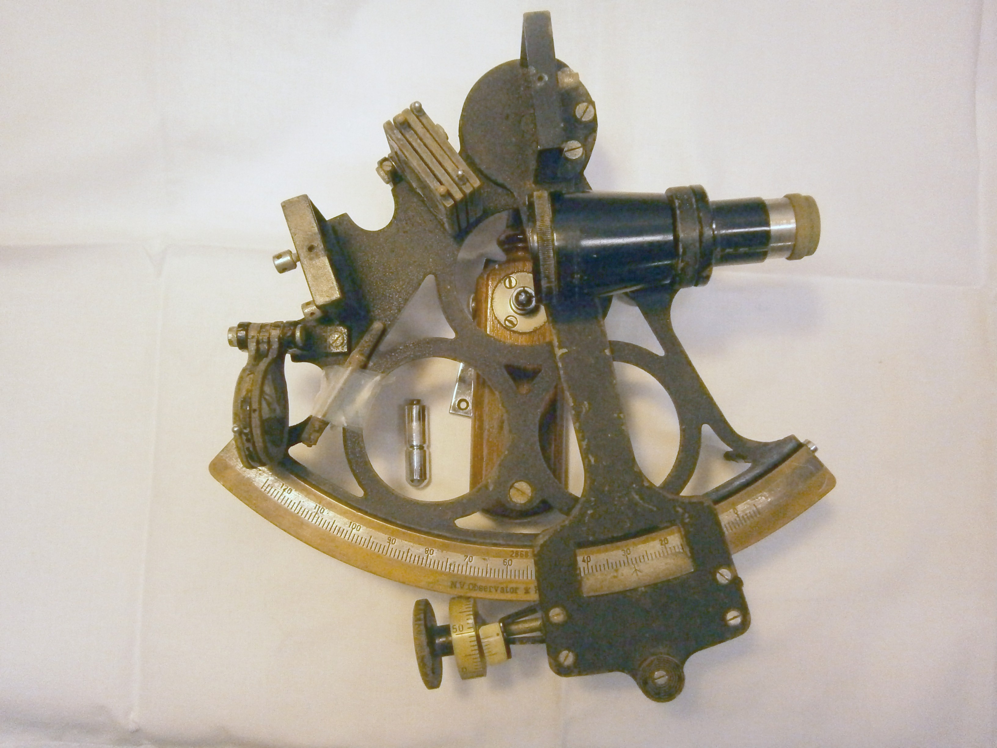
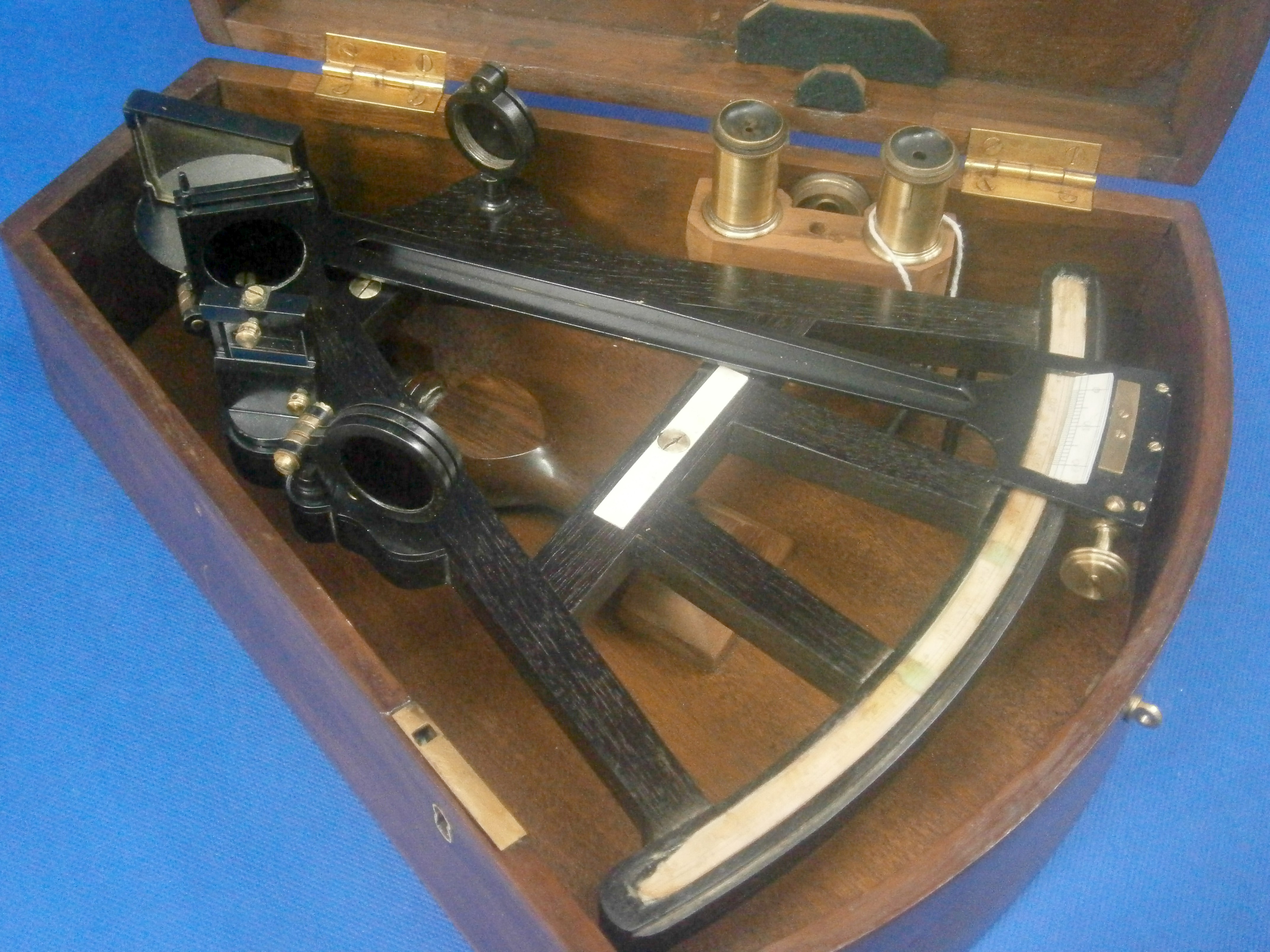
Frontispiece*: Before.

Recently I acquired a 1940’s  sextant by Observator of Rotterdam which I knew was not perfect, but the extent of the imperfections did not become fully apparent until it arrived about two weeks ago. The seller had very fairly pointed out a broken leg and a broken peg on the device that is supposed to secure the instrument in its case (Figure 1), and the absence of mirrors and their clips was evident from the photographs. Unfortunately, the second peg of the securing device gave way while in transit, so that the sextant rattled around in its case and the horizon mirror bracket got distorted (Figure 4), the telescope rising piece got both twisted and bent and the micrometer worm shaft got seriously bent (Figure 6).

leg-1

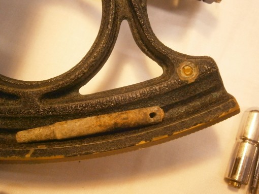
Figure 1: Broken leg and peg  as found

I have dealt with how to mend broken legs, using this instrument as an example, in my post of 7 October 2016, Mending Broken Legs, so will not write any more about it here.

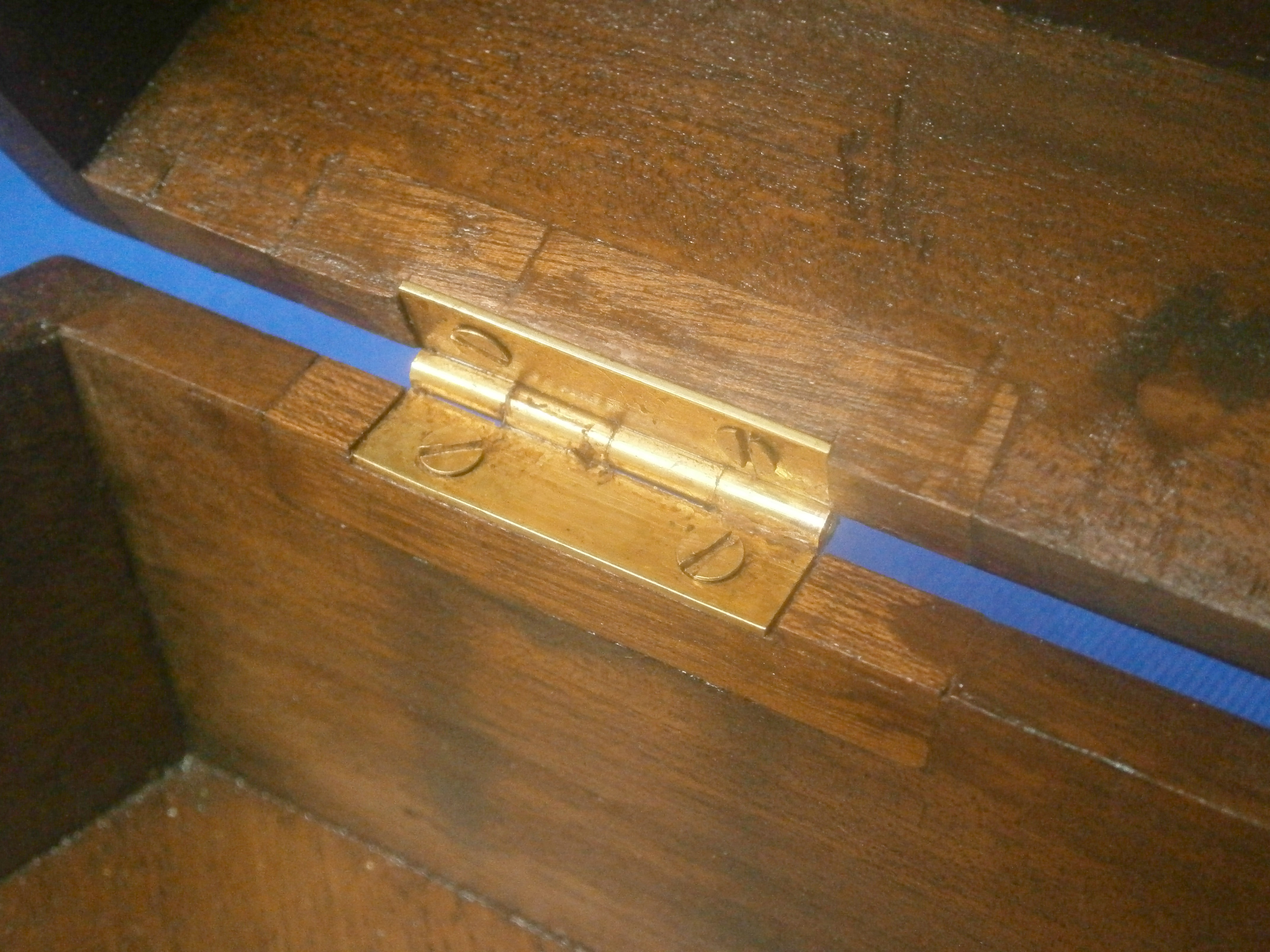
The pegs on the securing device were riveted into a plate which was screwed firmly to the base of the case (Figure 2) and all that was needed to re-secure them was to clean up their bases and, using the ball of a ball-pein hammer, to rivet them back in their holes.

holding-device-001

Figure 2: Device for holding sextant in its case.

The device is not well suited to its task. The pegs each pass through a hole in the handle of the sextant and, projecting into the upper holes which is lined with a brass bush is a spring-loaded pin (Figure 3). This latter is supposed to engage in a groove in the upper peg, but, while it may locate the sextant, it does not secure it very well. I plan to add a couple of wooden buttresses to the lid of the case, so that when it is closed the sextant will be held securely.

holding-device-002

Figure 3: Spring-loaded pin that “secures” sextant.

The distorted horizon mirror bracket (Figure 4) had most of the distortion removed by giving a squeeze in a vice and then a few well-directed blows  with a soft-faced punch did the rest

mirror-bracket

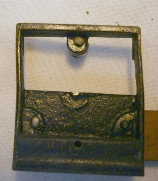
Figure 4: Distorted horizon mirror bracket.

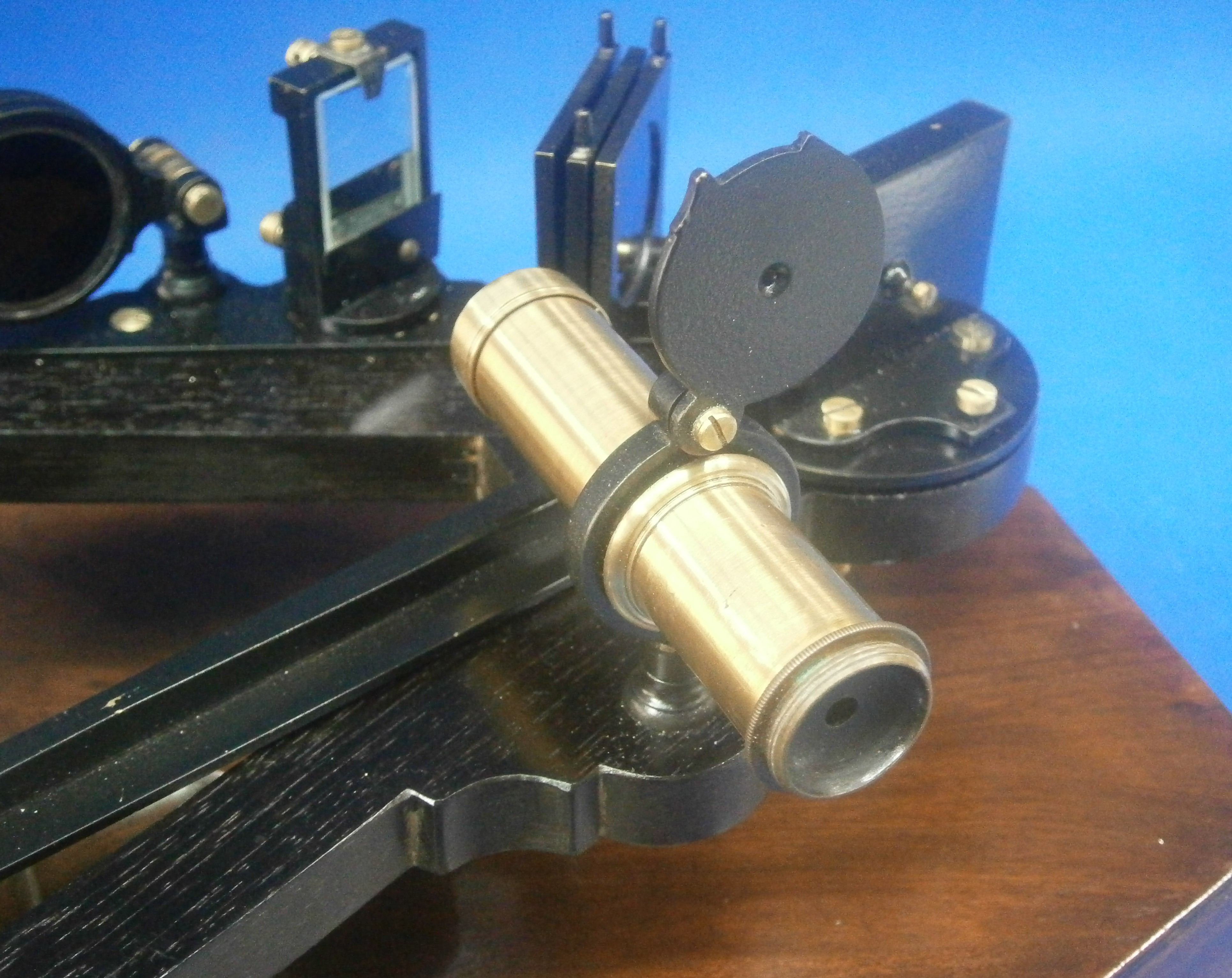
The extent of the damage to the telescope rising piece is not immediately apparent from Figure 5, though with a little imagination, a twist is apparent, and it was certainly obvious that the telescope was not pointing towards the horizon mirror. The objective lens was also canted downwards so that instead of clearing the index arm, it was jammed against it. Straightening the part simply involved removing the telescope and its ring and placing first the square upright in the vice to untwist the soft brass, followed by clamping the ring to straighten the upright in two dimensions.

rising-piece

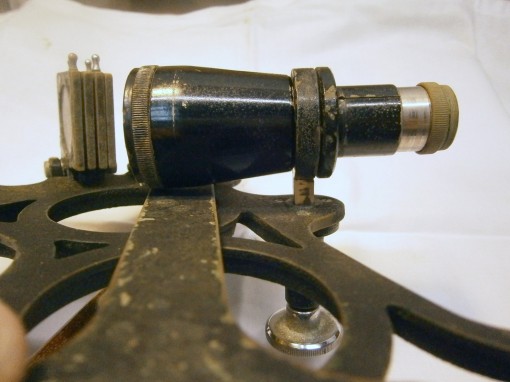
Figure 5: Bent telescope rising piece.

Straightening the micrometer shaft was altogether more complex, as not only was the shaft bent, but the bracket that holds the index was also distorted (Figure 6).

shaft-1

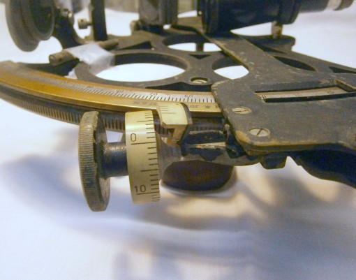
Figure 6: Bent micrometer worm shaft.

A brief account of the micrometer mechanism will perhaps help the reader to appreciate the problem better. The parallel worm lies between two reduced portions of its shaft and the walls of each reduced portion are conical in shape. The parallel parts of the shaft that lie between the conical portions make no contact with the bearings. Only the conical parts do so and, if properly made, by no means a simple task, when assembled all axial and radial play is removed while still allowing the shaft to rotate freely (Figure 7). For an account of making a similar new micrometer shaft and worm, see my post of 6 July, 2009, A Worm Turns.

micrometer-shaft-001

Figure 7*: Micrometer shaft in its bearings

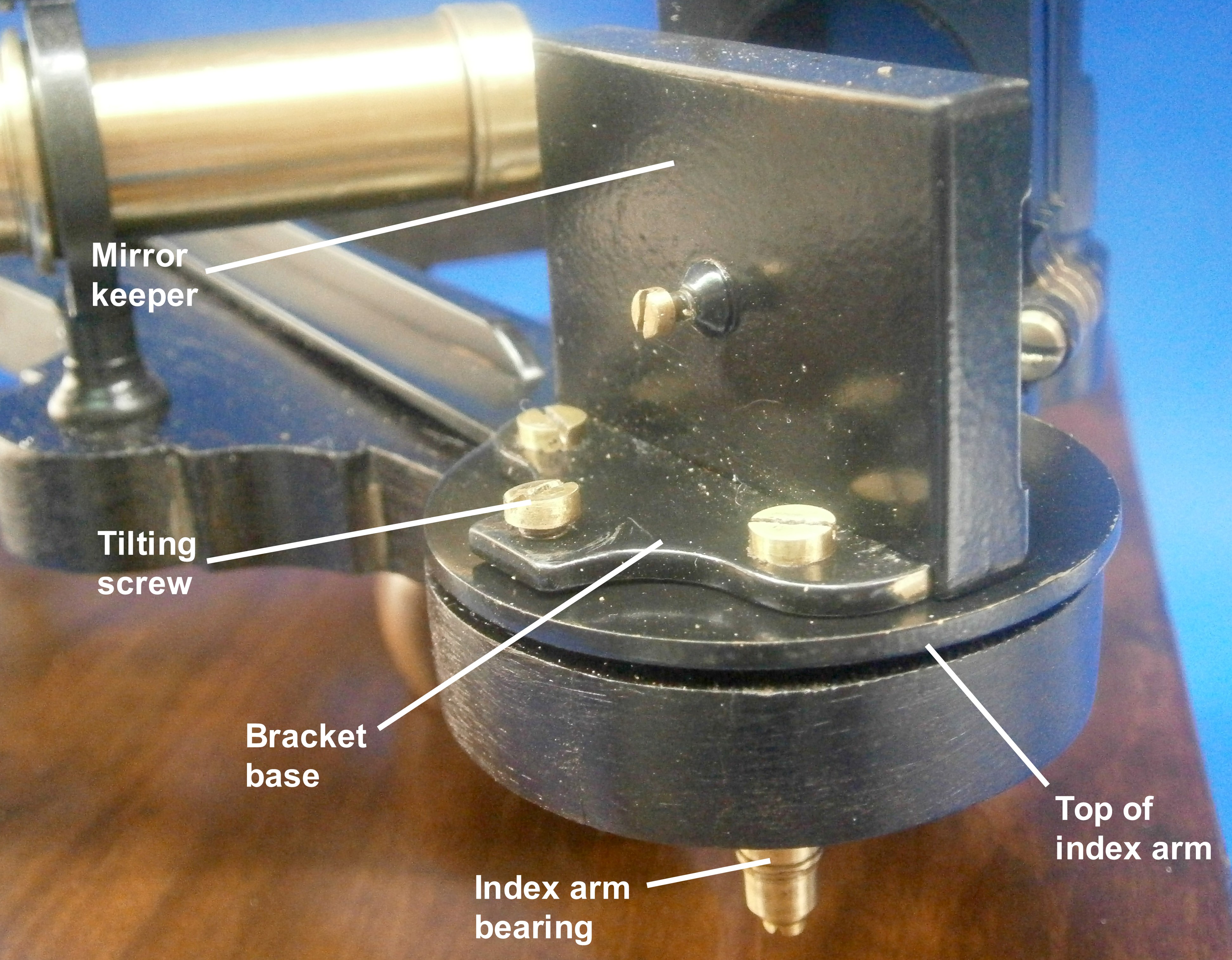
The bearings form part of what I have chosen to call the swing arm, a brass casting that is held between two trunnions in the form of screws with hardened, conical ends, that allow the arms and the included micrometer worm to swing in and out of engagement with the rack against the pressure of a leaf spring (Figures 8 and 10). Note how the index of the micrometer drum is carried on a slender bracket that is attached to the sides of the front bearing.

micrometer-shaft-003

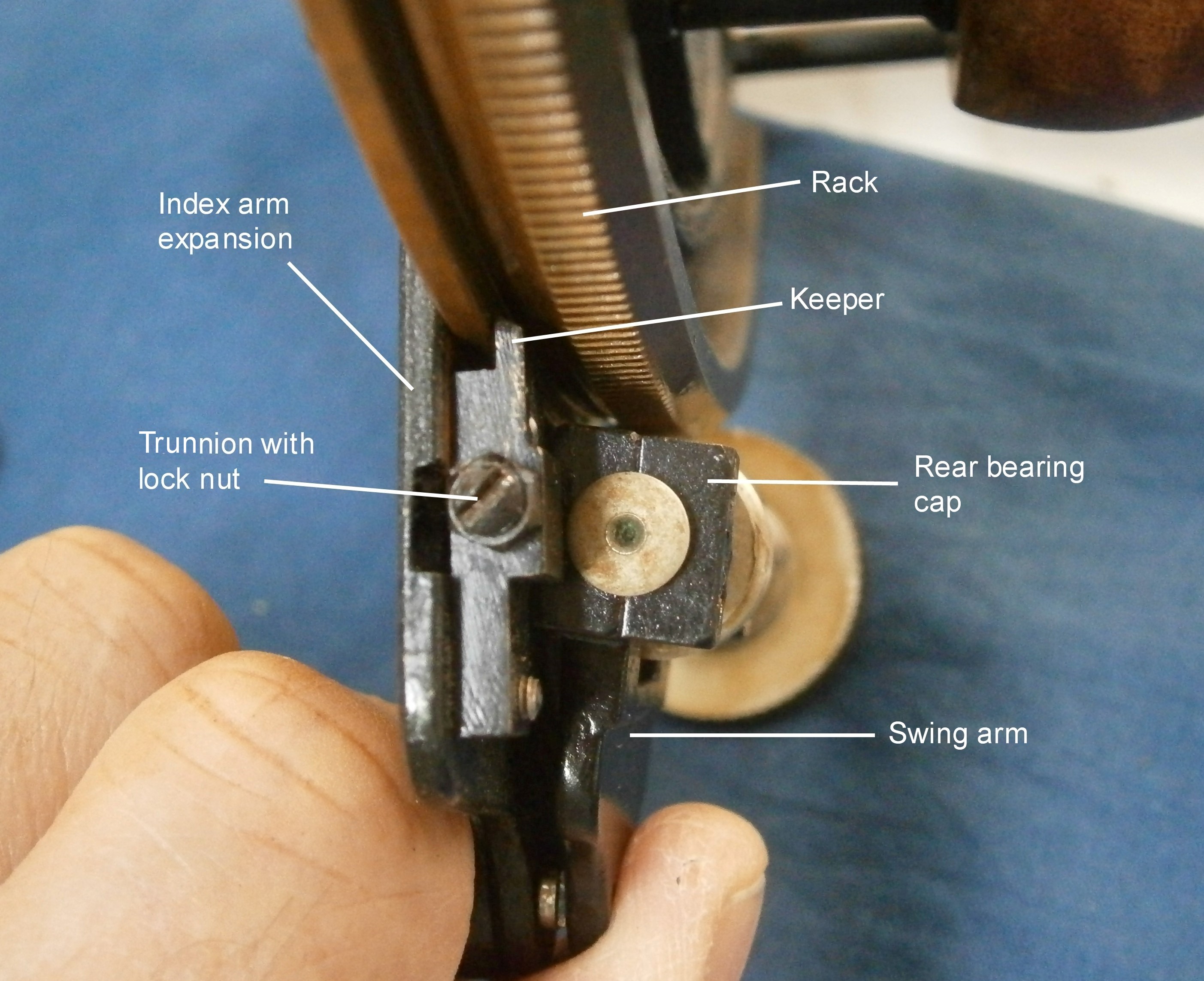
Figure 8*: Swings arm and trunnion.

The trunnions are adjustable to allow all play to be taken up while allowing free rotation. The trunnions are then locked in place by means of lock nuts. The blocks in which they run are extended to form  keepers that prevents the index arm from lifting off the frame.

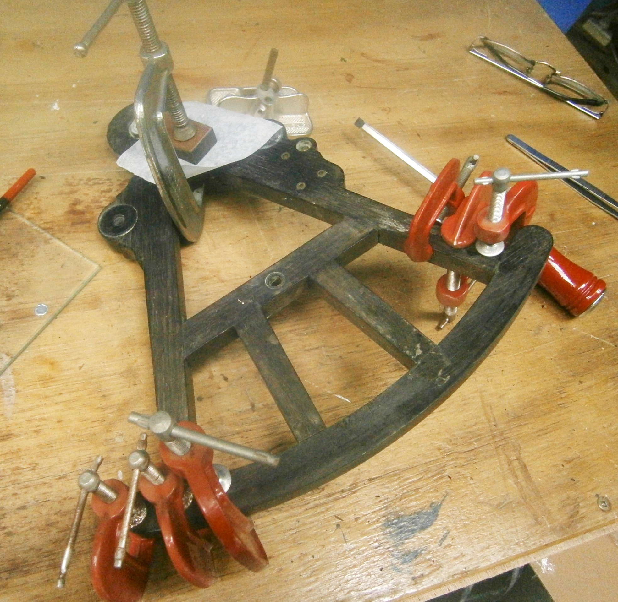
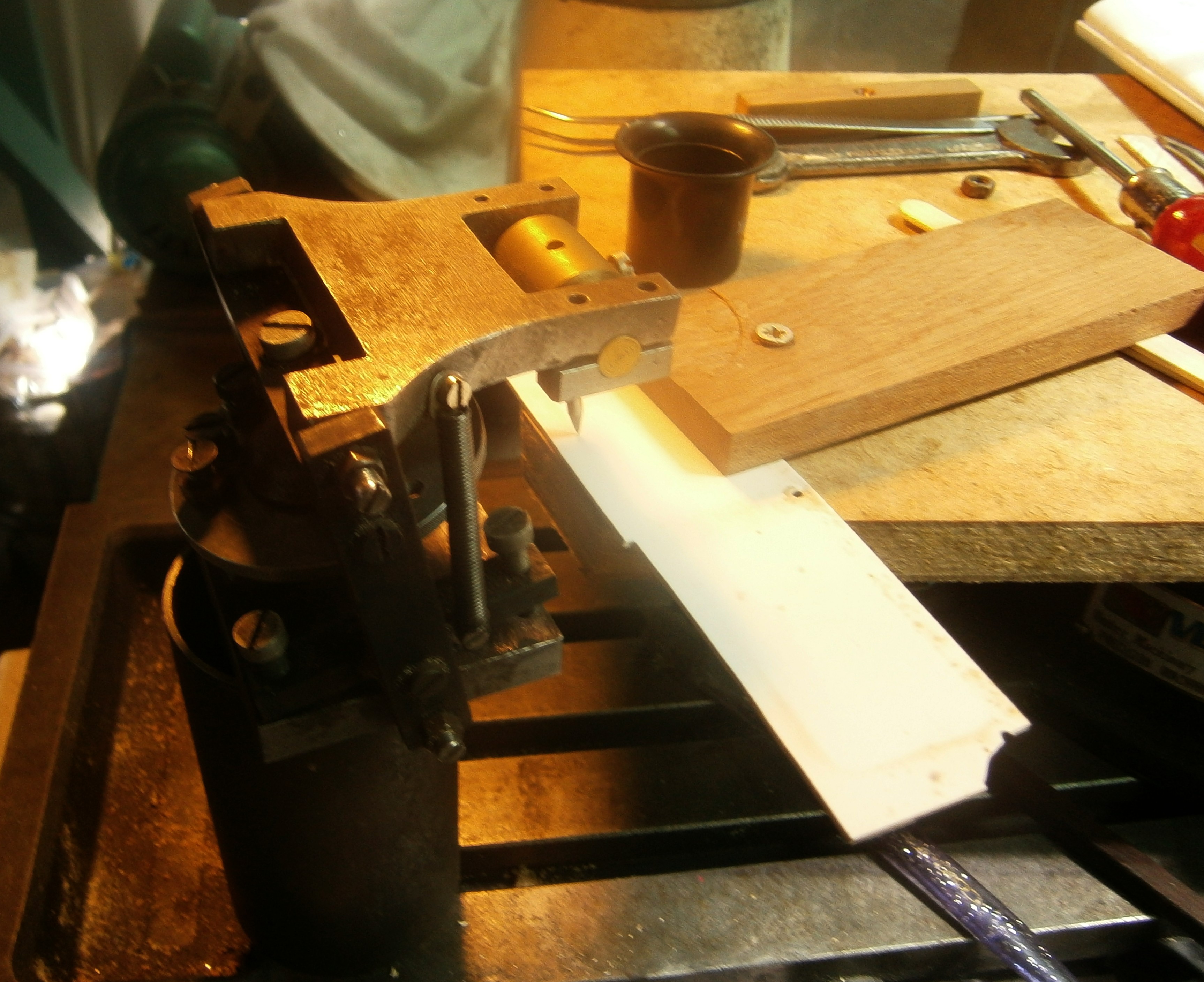
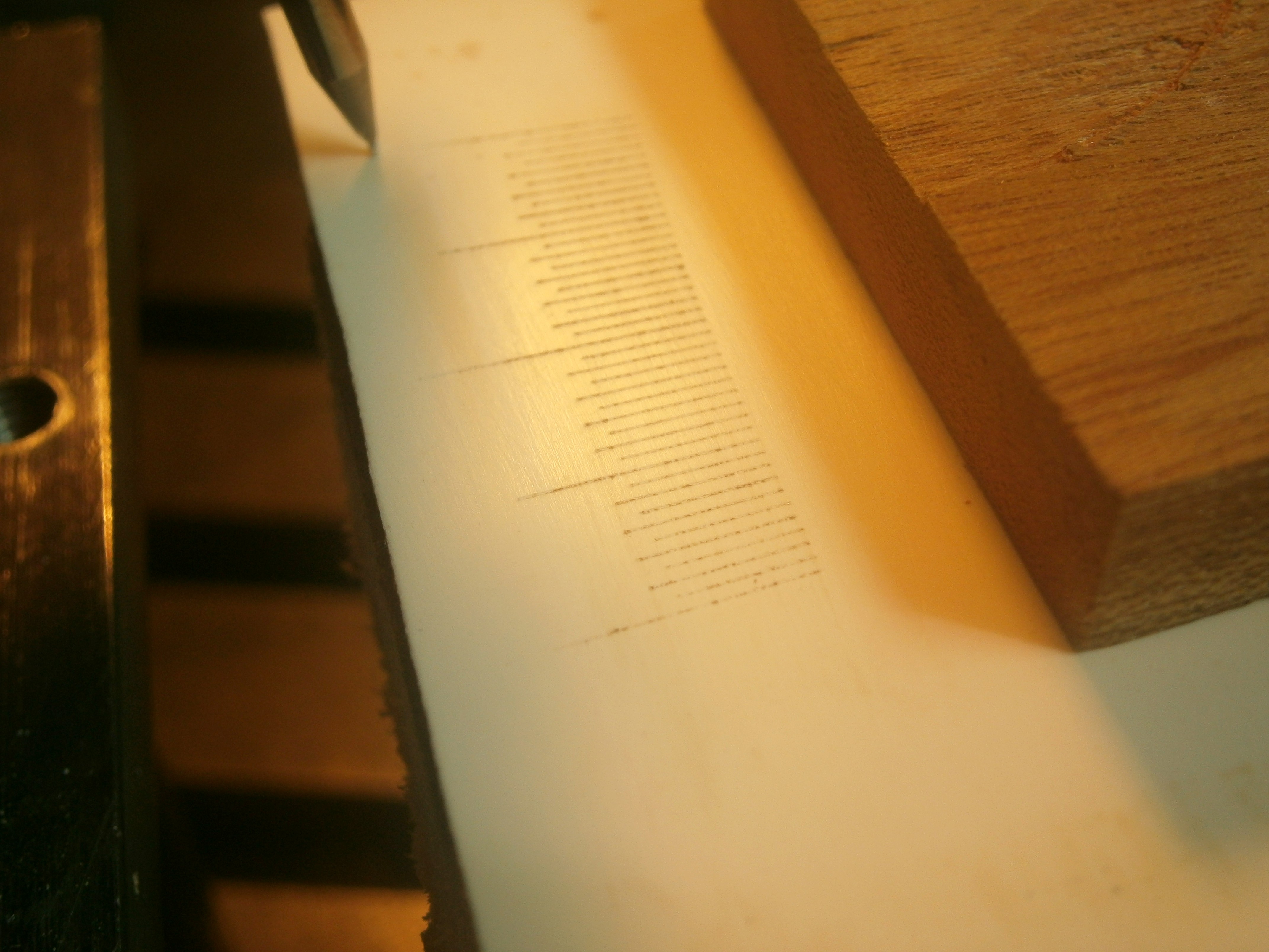
When straightening a bent shaft it is difficult to ensure that one does not end up with two bends in opposite directions, but in this case, the bend took place at the narrow parallel portion of the shaft that is not normally in contact with the bearing and which takes no part in its alignment. Figure 9 shows one way to straighten the shaft to restore its alignment with the worm.

shaft-straighten

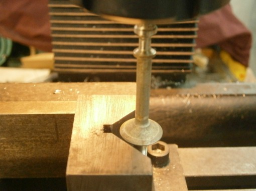
Figure 9: Straightening the shaft under control.

The 15 mm diameter worm is held in an ER collet in the spindle of my milling machine and a 90 degree vee block is held in the machine vice as a guide to alignment. While the shaft rotates slowly, the position of the block is adjusted so that the point of maximum eccentricity is aligned midway between the sides of the bloc, when rotation is stopped and the machine table moved to give the shaft a nudge in the right direction. The shaft is alternately rotated and nudged until no eccentricity can be detected in the part of the shaft that carries the micrometer drum.This of course only guarantees that the drum and the worm are concentric, but these are the important alignments. While some slight eccentricity of the front bearing remained, it was of the order of only 0.03 mm.

The index bracket had taken on a curious shape and in trying to straighten it, it became partially detached from the side of the front bearing. As it had been soft soldered into place, I completed the detachment by heating with a small flame and this allowed me to straighten its slender sides using a combination of vice and punch. T

his then left me the problem of re-attaching it so that the index would be correctly aligned. Figure 10 shows how I did this (note too how this photo shows the trunnions and their mountings clearly).

copy-of-swing-arm-structure

Figure 10*: Soldering jig.

I first turned up a bush of the same diameter as the micrometer drum to fit in place of the drum, and of a length equal to the combined thickness of the drum plus index. I then bored out one end of the bush to a depth equal to that of the thickness of the index. When in place (Figure 11) the bracket could then be clamped to it in the correct orientation and the arms of the bracket sweated back into place with soft solder.

OLYMPUS DIGITAL CAMERA

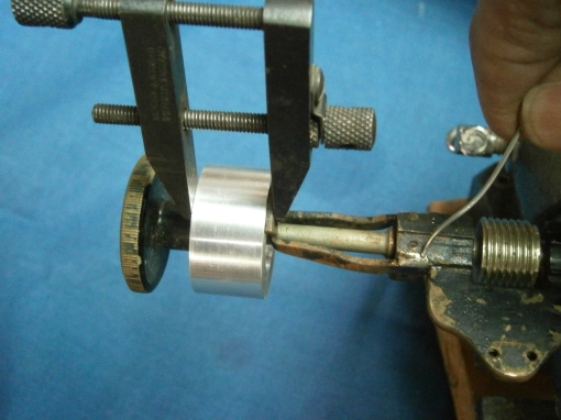
Figure 11: Soldering jig in place.

Happily, when the micrometer mechanism was re-assembled, everything ran smoothly, but when I next have an auto-collimator out on my surface table I will check for eccentricity errors of the drum. None is visible to the naked eye. In the course of dismantling the index shades for painting and lubrication, the head of the (steel!) screw that prevents the shades mounting shaft from rotating broke off, leaving me with one last task, that of drilling out the broken screw and fitting a new brass one (Figure 12). The process is the same as for drilling out broken legs.

OLYMPUS DIGITAL CAMERA

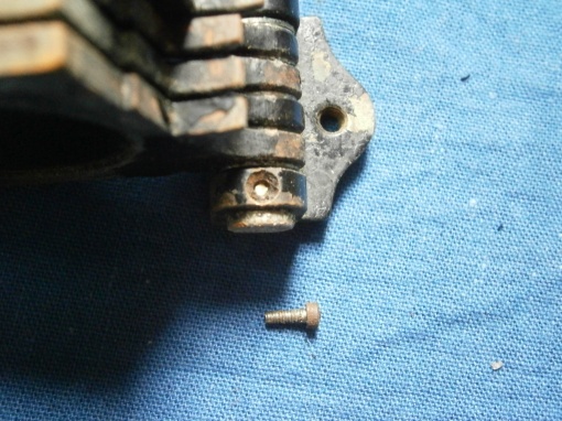
Figure 12: Broken screw and its replacement

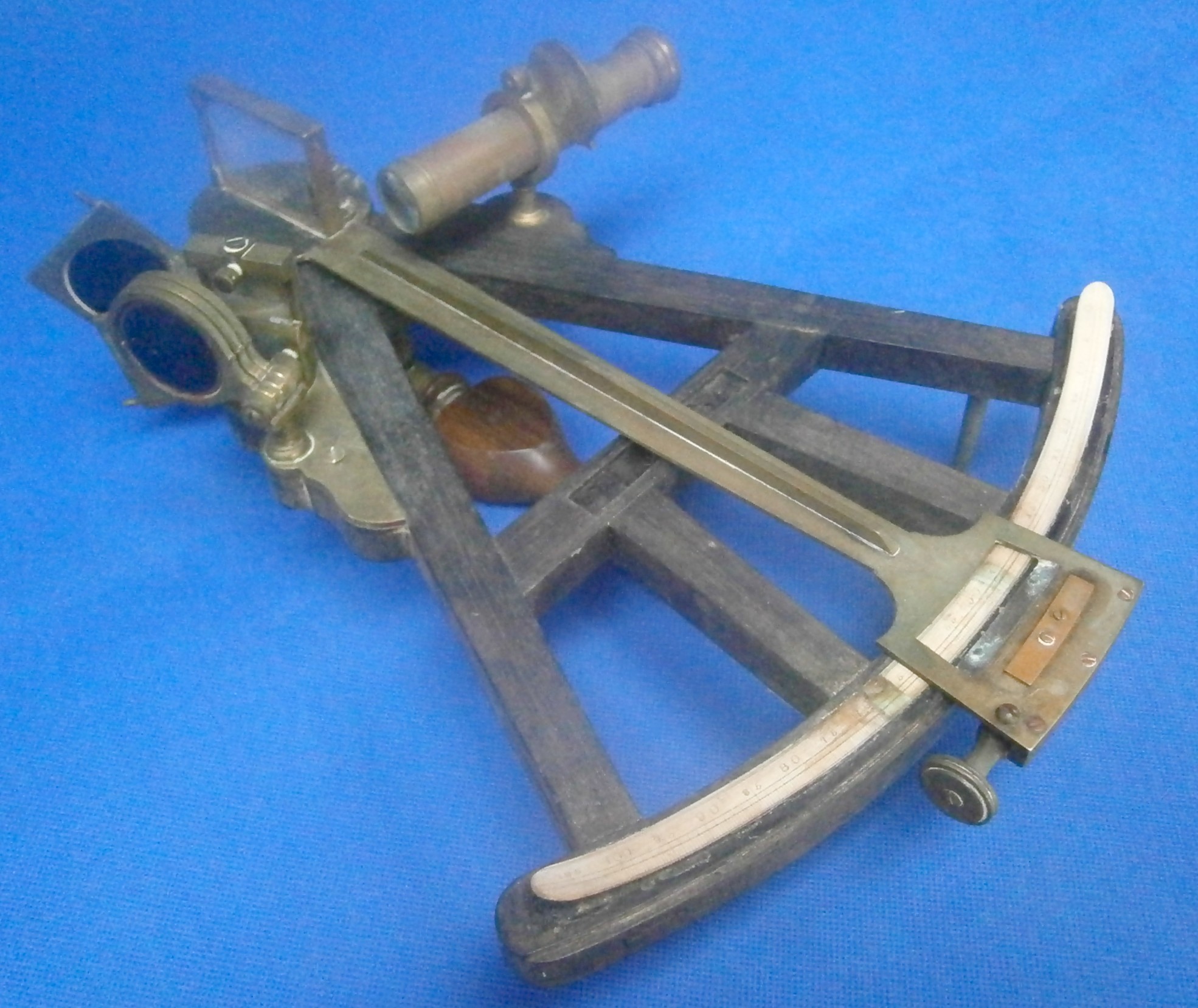
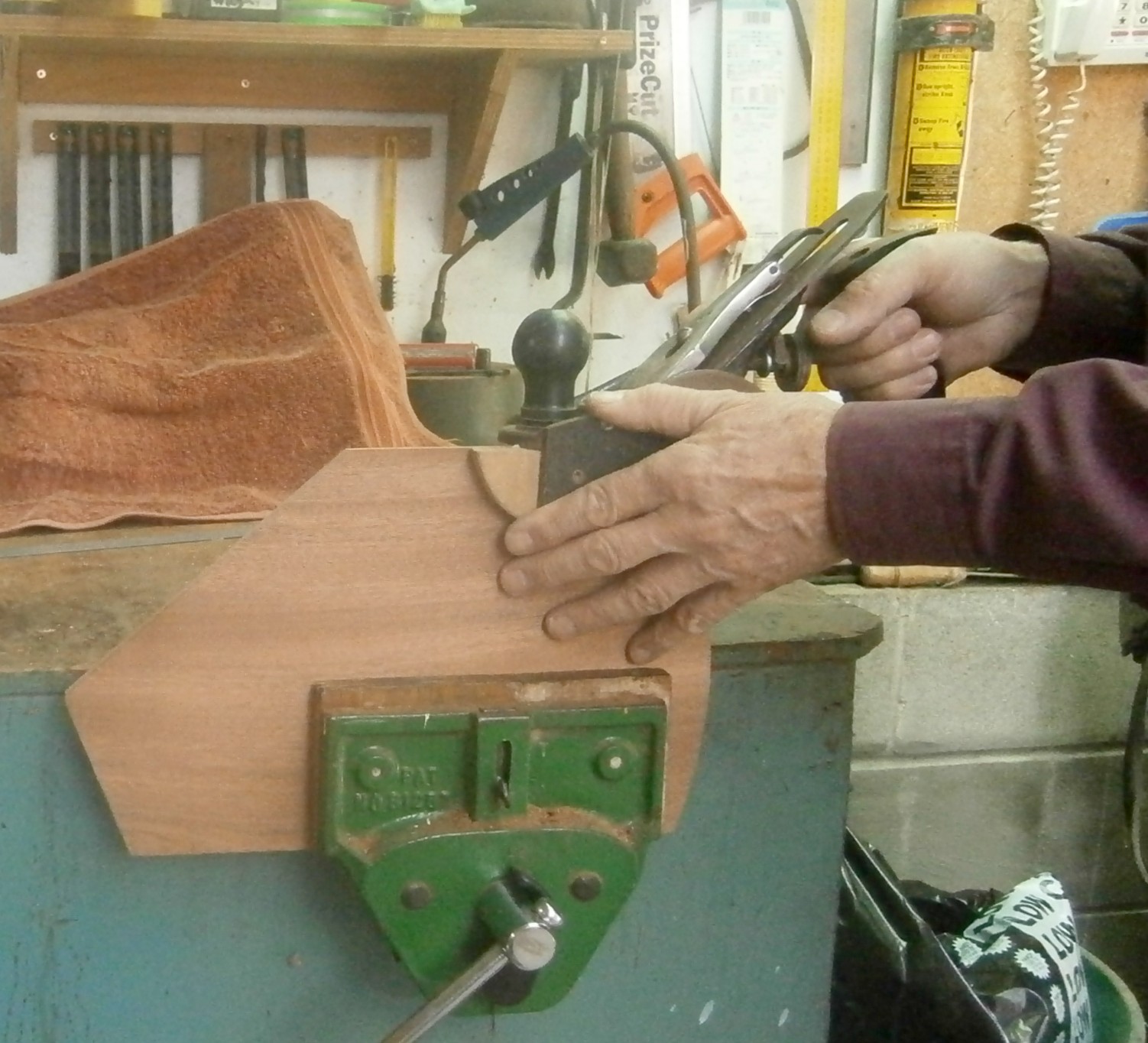
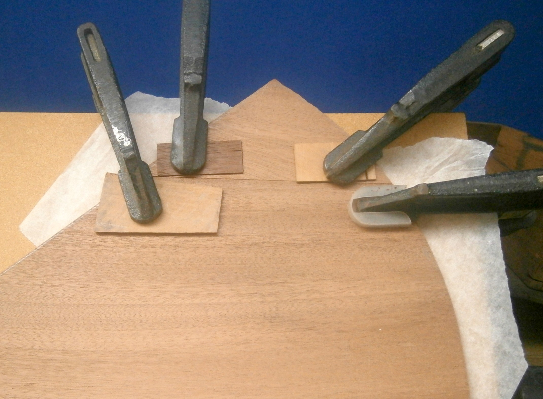
After making new mirrors (Posts of 11 February 2009 and 27 March 2011) and clips, all that remained was to take everything apart, clean, strip and respray everything, re-assembling, greasing and oiling where appropriate, and to re-finish the mahogany case (Figures 13 and 14).

ga-finished

Figure 13*: Finished sextant in its case

handle-1

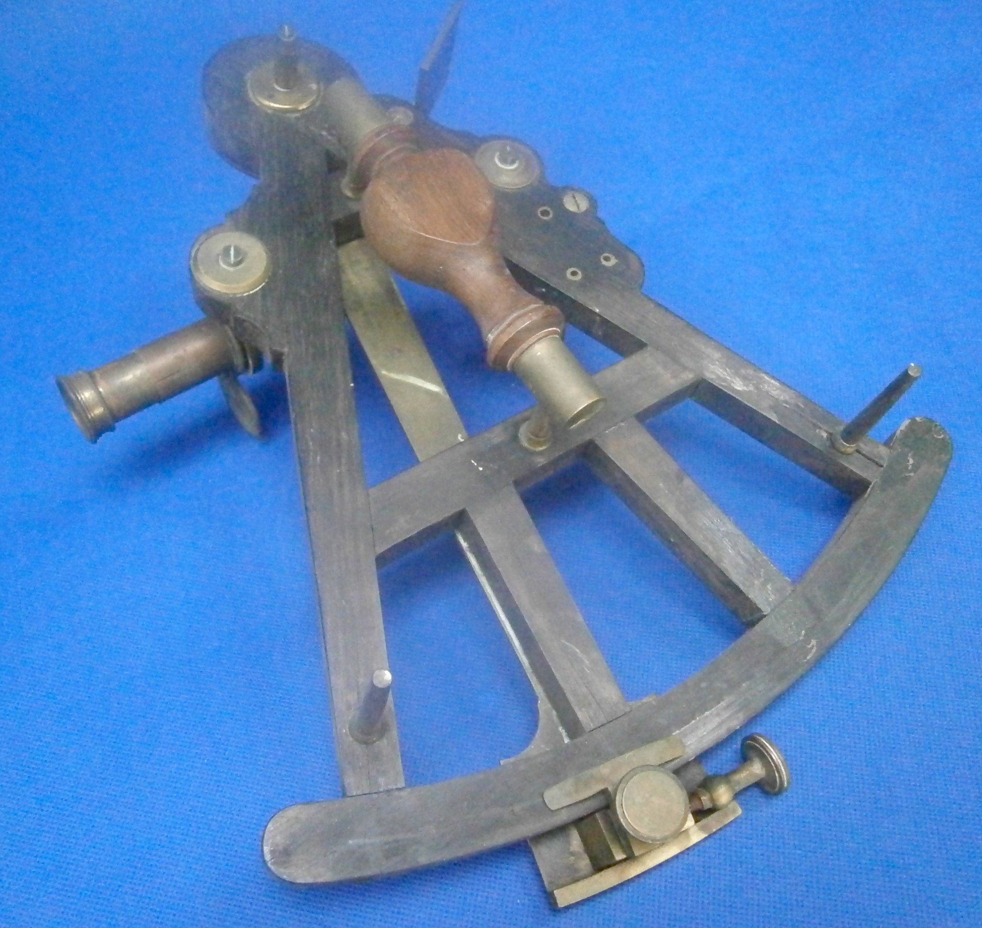
Figure 14 * Rear face of finished instrument.

If you have enjoyed reading this blog post, you will probably enjoy owning a copy of my book, “The Nautical Sextant“. You may also enjoy reading my book “The Mariner’s Chronometer” Both are available through Amazon, Paradise Cay and Celestaire.


Restoration of an early C19 ebony quadrant

18 12 2014

The preceding posts in this category cover : “C Plath battery handle structure; “C Plath sextant lives again”; “C Plath Micrometer Sextant”; “A Damaged Rising Piece”, “SNO-T Mirror Bracket Repair”,  “A Worm Turns”, “The case of the broken screw”, and “Worm with wrong thread angle?”

As I have a limited budget to spend on my hobbies, most of the sextants that I buy are damaged to some extent or missing parts or corroded or all three, but where would the fun be in buying pristine instruments? A little while ago, an ebony quadrant which I guestimate to be from the first half of the nineteenth century came into my hands for much less than an instrument in good condition would cost. My experience may help readers with their own restoration projects. I do not claim to be an expert wood worker or that there are not other ways to proceed, only that my methods work after a fashion.

First a word about the term quadrant. Most mariners of the time would observe a heavenly body to obtain latitude, either by observing the maximum altitude of the sun to obtain local noon or, in the northern hemisphere only, by observing the altitude of Polaris, the Pole Star, again obtaining latitude with only small corrections and the minimum of calculation. As the altitude of heavenly bodies never exceeds 90 degrees, an quadrant would do for the observations. It was also often called an octant, Hadley’s quadrant or simply “a Hadley”.  As rotation of the index mirror through a given angle rotates the reflected ray through twice this angle, each degree on the scale of an octant (or, for that matter, a sextant) is only half a degree of a full circle, so that 90 degrees of measured angle or a quarter of a circle can be accommodated on a scale of only an eighth of a circle in length, hence “octant”. More sophisticate navigators might attempt to obtain their longitude by the method of lunar distance, for which a sextant, able to measure altitudes up to 120 degrees, was required. Figure 1 shows the face of the instrument as received. (Clicking on the pictures enlarges them. Return to the text by using the back arrow). The frame is of heart ebony, a black or dark brown African wood which is very stable and hard. It is also unfortunately prone to splitting and flaking. The figure shows that the octant is very dirty, it lacks the vernier scale and name plate, and the ivory main scale or arc has detached itself from the limb.

Figure 1: Face of octant as found.

Figure 1: Face of octant as found.

The rear view, shown in Figure 2, shows some of these cracks at each end of the limb where the legs of the sextant have been screwed into the back of the frame. It is not possible to see that the tenons are loose in their mortises and that there was a large flake loose in the vicinity of the rear of the index arm bearing. Happily, all the brass parts, including a small Galilean telescope and a sighting tube, were intact. It is interesting to see in the rear view that there are three brass inserts that seem to have no function in this instrument. Some earlier instruments had elaborate methods for correcting side and index error and these brass inserts would have been used to attach these devices. Plainly, there were specialist frame makers, scale dividers, telescope makers, shade and mirror bracket makers and so on. The person who placed his or her name on the instrument, and there was at least one female instrument maker, was very often merely the person who assembled bought-in parts into a whole, rather like modern-day car makers. Perhaps an instrument maker was told that he could have any frame he liked as long as it was the one that the frame maker had in stock.

Figure 2 Rear face of octant as received.

Figure 2 Rear face of octant as found.

Figure 3 shows the mahogany case which from its condition had plainly not been stored in a dry place. As all the joints were loose and the box lock interior was a mass of rust, perhaps it had even been submerged at some point. The base had so many splits in it, with loss of wood around the steel nails that it was beyond repair. One hook latch was still present and it was possible to pull apart the joints easily after removing the top and bottom. The steel screws securing the  hinges had not only corroded beyond saving, but the swelling of the rust had also partly destroyed the surrounding wood. Only one hinge remained.

Figure 3: Case as found.

Figure 3: Case as found.

In the lid were the remains of a label of William de Silva shown in Figure4. In the census of 1881 there was a William de Silva, “Optician” aged 59 years,  living in Liverpool. He was possibly the son of Manuel de Silva noted in the census of 1841 as having been “born in foreign parts.” William had a son, also William, whose age in the 1881 census was given as 36, occupation Master Mariner. Prince’s Dock was begun in 1810 and completed in 1821. Bath Street overlooks the dock. It seems safe to say that the instrument was at some time sold by De Silva and may even have been made by him, in which case it seems reasonable to place it in the first half of the nineteenth century.

Figure 4 : Label of probable maker.

Figure 4 : Label of probable maker.

Figure 6 shows some of the frame repairs in progress. All the brass parts have been removed, the mortise-and-tenon joints re-glued  and the splits repaired. The latter is done by prising  open the split and introducing modern PVA glue into the split, using a fine blade or piece of shim stock to encourage the glue into the deepest recesses. The crack is then forced closed using as many cramps as can be accommodated. At the left of the picture it can be seen that the mortise cut into the right hand end of the limb has split apart and been re-glued. The large flake at the top has been glued back into place and a block of wood used to keep it there while the glue dries. Modern baking paper is very useful to prevent items sticking to things they ought not to. The ivory arc needed careful handling as it had shrunk and detached itself from each end, forming a curve in the process. A previous owner had tried unsuccessfully to replace it using contact adhesive and removing the old glue was a quite difficult job.. I replaced the arc using a modern gap-filling adhesive, but was not entirely successful at preventing splitting at the high end of the arc. However, the shrinkage of the arc meant that it could never again be used in anger so I was not too upset.

Figure 5: Frame being re-glued.

Figure 5: Frame being re-glued.

Re-assembling the case was not too difficult. While the walls and top were apart, I used a cabinet scraper to remove all the old and perished varnish. I find that once the knack of sharpening the scraper has been learned, this is a quicker method of getting down to bare wood, as well as needing less exertion than sanding.  Some splits and shrinkage cracks meant I had to have recourse to glue and mahogany paste to make good the losses. As noted above, the base was beyond repair, so I made a new one from some 5 mm thick mahogany board, cut slightly over-size. My board was not wide enough to cover the whole of the base, so I added a piece to one corner. To make a rubbed joint to unite two pieces of board with glue, it is essential for maximum strength that the edges should be both straight and square. Figure 6 shows how I planed the edges with a smoothing plane fitted with a home-made fence to ensure the edge was square.

Figure 6: Edge planing without tears.

Figure 6: Edge planing without tears.

Figure 7 shows a method of clamping boards of irregular shape while the joint dries. A piece of modern baking paper separates the two parts from a piece of flat and true board. Two clamps hold the large piece immobile and another two clamps hold the smaller piece in contact. It is tapped lightly with a soft mallet until a glue line appears and then the clamps are tightened to hold the boards firmly together.

Figure 7: Clamping an edge joint.

Figure 7: Clamping an edge joint.

Figure 8 shows the finished result.

Figure 8: Finished joint.

Figure 8: Finished joint.

The way the top and bottom of sextant cases are attached varies quite a lot. Unfortunately, steel panel pins were often used on the part of the case most likely to get wet, the bottom, as well as on the top. Slightly higher class cases used brass screws on the top, but even very respected makers sometimes left the unseen bottom to steel pins. Only the best cases had brass screws top and bottom and the really high class ones have the screw slots lined up. The staining from corroded steel pins is difficult to remove and often the pins themselves break as they are being withdrawn so that all one can do is to drive the remnants below the surface and start again with brass pins or screws in different places. Whichever type of hardware is used, it is easier to start by gluing the base or top to the carcass. Figure 9 shows this in progress. A large variety of clamps or heavy weights is indispensable to get a good result.

Figure 9: Base being glued to sides.

Figure 9: Base being glued to sides.

Figure 10 shows excess base being planed away using a block plane on the end grain. I am taking a fine “sciving” or oblique cut. Experienced woodworkers will not need to be reminded not to plane right to the corner, to prevent splitting, but I sometimes forget to reverse the direction of the cut before reaching the corner and others might too.

Figure 10: Planing across the grain of the base,.

Figure 10: Planing across the grain of the base,.

Figure 11 shows the mess left by the swelling of the rusty hinge screws.

Figure 12: Damage from rusty screws.

Figure 12: Damage from rusty screws.

I tried filling them with epoxy putty, but the screws refused to go where I wanted them, always following the path of least resistance, so in the end I cut out all the damaged wood and let in pieces of mahogany Figure 13) for the pair of new hinges. I was not able to match the single remaining original hinge, so replaced them with a pair of mdern brass hinges.

Figure 13: Case repair in vicinity of hinges.

Figure 13: Case repair in vicinity of hinges.

Once the repairs to the case  were complete, I stained the wood to get an appearance similar to that of old dark mahogany and finished with several coats of modern varnish, sanding lightly between each coat. Figure 14 shows the result for the exterior. I used the remaining hook latch as a pattern in order to cut out and file to shape a new latch from 2.5 mm brass sheet and turned up and filed new eyes to match from 12 mm brass bar.  After soaking it in CRC I was able to remove most of the rust from inside the lock and file an old key I had spare to shape. Rather to my surprise, the lock now works effectively. I postponed work on the pockets and keepers inside the case until I had finished the rest of the restoration of the instrument. itself.

Figure 14: Finished exterior of case.

Figure 14: Finished exterior of case.

Ivory is no longer possible to obtain except from the keys of scrapped pianos and even those are for the most part ivorine, an early form of cellulose-based plastic. I had a few pieces from the scrapped scale of a distance meter and soon had let in a piece to form a new name scale, though for the time being it remains nameless. The ivorine doesn’t have the creamy texture of real ivory, but at least I am following the practice of many professional restorers of leaving the restored part obvious. The vernier scale was one or two orders more difficult. After working out the angular distance apart of the individual graduations I then had to set up the ivorine at the correct radius on the extended table of a rotary table. To cut the graduations so that they do not look amateurish I used a scribing device that I made many years ago and had not used since (Figure 15).

Figure 14: Scriber.

Figure 15: Scribing vernier.

The makeshift, rough version has, as is often usual with me, become the permanent version. A parallelogram mechanism keeps the scriber moving in the same plane under spring pressure and a disc with stops of different heights determines the lengths of the graduations. Figure 16 shows the partly finished scale.

Figure16: Radial lines scribed.

Figure 16: Radial lines scribed.

Once the radial lines were finished, the same scriber was used to mark out the remaining lines, together with guide lines for rough cutting out. The edges were then filed to shape and the underside bevelled to a knife-edge so that the edge of the scale came flush with the main scale (Figure 17). Usually, ivory vernier scales were secured to the index arm with two brass rivets, which caused staining and splitting as the rivets corroded and the ivory shrank. I simply glued the vernier scale into place with epoxy glue.

Figure 17: Completed vernier scale

Figure 17: Completed vernier scale

There was little to do to the remainder of the instrument except to clean the brass parts, repaint them where appropriate and to polish and lacquer the parts like screw heads that were usually left unpainted. While sextants and octants of this period often are shown bright and shiny, on several period instruments that I have handled, I have found traces of paint to guide me on what was usual. There are one or two points of design interest that may not be familiar to some readers. I will be covering the evolution of sighting devices in some detail in another post in the category Evolution of sextant parts, so will give only an outline here.

Figure 18 shows how the index mirror was set perpendicular to the frame. The mirror is held against three points on the front of the right-angled bracket by means of a clip or “keeper”. A central screw when tightened pulls the clip against the front of the mirror and holds the latter firmly against the three points on the front of the bracket. Two lateral fastening screws pass through clearance holes in the base into holes tapped in the index arm. A third screw, labelled “tilting screw” passes through a tapped hole in the base of the bracket so that when the fastening screws are slackened a little, the base can be tilted to the desired right angle be adjusting the tilting screw. This is not a very satisfactory method, as the heavy handed could (and did) bend the base or strip the thread of the screw or hole.

Figure 18 Index mirror adjustment.

Figure 18 Index mirror adjustment.

Figure 19 shows the pinhole which, at 2 mm in diameter, gives a very wide angle view, compared to that given by the Galilean telescope shown in Figure 20. The diameter of the objective lens of this telescope is a mere 18 mm with a magnification of 6 times. The field of view of a Galilean telescope depends on the diameter of the objective and inversely as the magnification, and in this telescope the field of view is only about 3.5 degrees. Because of this, if Captain James Cook’s practice is anything to go by, sailors used the telescope only when the sea was calm, as it was otherwise difficult to keep the body in view, due to the motion of the ship. The pinhole can be swung aside to allow the telescope to be screwed into the bracket. It can also be swung through 180 degrees so that the hole is offset away from the frame, to give a wider view of the horizon.

Figure 18: Pinhole.

Figure 19: Pinhole.


Figure 19: Telescope in place.

Figure 20: Telescope in place.

A coat of shellac brought back the frame to a pleasing finish and Figure 21 shows the completed instrument in its restored case, with pockets repaired and glued into place, and felts replaced.

Figure 21: Restoration complete.

Figure 21: Restoration complete.

Because of the shrinkage of the ivory main scale, this instrument is not of course a functional instrument any longer, but it is nevertheless an interesting representation of what the less prosperous sailing ship mariner might have used to find his latitude in the first half of the nineteenth century.

If you enjoyed reading this post, you might also enjoy my book The Nautical Sextant , available through amazon and good booksellers, and my book on the chronometer, The Mariner’s Chronometer, available only through amazon. The reviews on amazon will give you an idea what other purchasers thought of the books.


C Plath Battery Handle Structure

5 12 2012

The preceding posts cover : “C Plath sextant lives again”; “C Plath Micrometer Sextant”; “A Damaged Rising Piece”, “SNO-T Mirror Bracket Repair”,  “A Worm Turns”, “The case of the broken screw”, and “Worm with wrong thread angle?”

A new friend recently sent me a battery handle from a C Plath sextant to reconstruct. The sextant had been stored under a sink which had had  a long-term leak and when the leak was eventually discovered, the lady of the house banished the sextant, in its case,  to the garage. As she had no key to the case, there the sextant languished for twenty years until my friend rescued it. The index mirror frame had corroded to a few scraps of aluminium alloy and the horizon mirror frame was nearly as bad. Corrosion had also affected the battery handle, which, fortunately, had no batteries in it, but the screw cap at the bottom had seized and both switch buttons lay free. He could press them in, but there was nothing to stop them dropping out. Some makers, and C Plath was one of the worst culprits, made their battery handles in such a way that it was impossible to deconstruct them if anything went wrong. In this case, corrosion had done the deconstruction, leaving behind a mystery as to how the parts should be re-assembled. Figure 1 shows the exterior of the handle. There are two switch buttons which operate independently to supply current to two sockets on top of the handle (Figure 2). A plug from one goes to the scale lighting system while the other was presumably to supply current to an artificial horizon attachment.

Switch 001

Figure 1: General arrangement of handle

Switch 003

Figure 2: Lighting sockets.

At the bottom of the handle is a brass bush or socket that is threaded for the battery cap. It is held in place by the threaded end of the lower pillar, which passess into a threaded cross hole and which also serves to conduct current from the negative pole of the battery to the frame of the instrument. A plastic liner reduces the interior diameter to suit two AA cells (Figure 3). The positive contact of the upper cell is held against the head of a large brass screw at the upper end of the interior of the  handle.

Switch 002

Figure 3: Lower end of handle deconstructed.

Figure 4 is a cross section drawing through the switch buttons.  The reduced diameter of the switch button passes through a phosphor bronze spring and then through a cross hole in the lower end of the socket. This serves both to capture the socket in place and to make electrical contact with it. A C-ring the other side of the socket sits in a groove and captures the button. When the button is pressed, the tapered end of the button makes contact with the large screw at the upper end of the interior of the handle. No doubt someone was congratulated for the elegance of this design, but of course, once the C-rings are in place the buttons and sockets cannot be withdrawn, as there is no means of accessing the C-rings to remove them.

Plath switch

Corrosion had done the job of removing the rings for me so my problem was how to  put everything together again. I began by removing the large screw to give the buttons some more  freedom of movement Having found a couple of small rings I did a trial fitting outside the handle and then greased a ring and sat it at the bottom of the hole, where the diameter of the hole reduces. Taking care not to forget the spring (which would have been disastrous) I then passed the reduced diameter of the button through the cross hole in the socket and entered the tapered end into the hole in the C-ring. A squeeze in a vice forced the ring up the taper and into the groove, where it will remain for ever. The other one received similar treatment and then the large screw contact was replaced.

At the lower end of the handle the problem was how to unseize the screw cap without causing unsightly damage to it by, for example, using a pipe wrench on it. One approach is to bore a hole in a scrap of wood to fit the cover. Then a radial split is sawn into the hole, the cover inserted into the hole and the wood squeezed in a vice to grip it. My solution was to make a bush to fit the cap from a scrap of thick-walled  aluminium tubing which I then split and squeezed in the jaws of a lathe chuck. I had no compunction about holding the brass socket with a pipe wrench to force the screw cap to yield and once it had yielded it was the work of moments to wire brush the corrosion away and remove any marks made by the jaws of the wrench with a smooth file.

The electrons now flow satisfactorily from the negative of the battery to the spring inside the cap and thence to the brass socket and via the lower pillar of the handle to the frame of the sextant.  From there they make their way through the lamp and the return wire to the plug which is inserted into one of the sockets. When the correspondng button is pressed, its end contacts the large screw and the current of electrons flows through the socket and the button return spring to the button and thence to the large screw, completing the circuit by entering the positive pole of the battery.


C Plath Sextant Lives Again

20 03 2011

The preceding posts cover : C Plath Micrometer Sextant; A Damaged Rising Piece”, “SNO-T Mirror Bracket Repair”,  “A Worm Turns”, “The case of the broken screw”, and “Worm with wrong thread angle?

Following the end of the Second World War, in November 1948 the venerable firm of Carl Plath was dismantled and its machinery distributed as war reparations, but by the autumn of 1950 it was able again to exhibit sextants at the Paris Shipping Salon. By the time Theodor Plath celebrated his 85th birthday in November 1953, the firm of C Plath was making between 1200 and 1500 sextants a year. About a month ago I received a C Plath sextant made in that year and have been spending some of my leisure time in restoring it.

Although the seller described it as being “in good condition”, this was far from the case, as there was widespread corrosion of screw heads, the mirrors had decayed, the index arm was jammed solid by verdigris and the release catch could not be operated, as the micrometer swing arm was seized solid. To add to the sextant’s woes, it had broken away from its moorings in its black bakelite case and bent the micrometer shaft as well as breaking off part of the plastic micrometer thimble. When buying second hand sextants, I routinely urge the sender to use plenty of packing inside the case to guard against such accidents, but on this occasion, my request had fallen upon deaf ears. As will be seen later, there was a hidden problem that became apparent only when I calibrated the instrument after restoring it.

Plath’s 1953 instrument showed little difference from instruments 20 years older. The bronze ladder frame of 162 mm radius had a conventionally placed rack and the design of the micrometer mechanism had not changed since it was first invented by the firm in about 1907. Though other makers made variations on the theme, the design was very sound and was copied, slavishly by Tamaya, and with minor modifications in attempts to have points of difference, by other makers.

In common with Tamaya, C Plath early realised the importance of light grasp in the optics and had large mirrors with telescope apertures to suit. My instrument came with a 6 x 30 prismatic monocular which gives an erect, bright image with a large field of view. Submariners of the US Navy in the Pacific Theatre in WW II had noted that by using such a monocular with their sextants, it was often possible to take accurate star sights in darkness, provided the observer’s eyes were fully dark adapted. Presumably, the experience of U-boat navigators was much the same and noted by C Plath, or there may have been liaison with Tamaya during the war. The latter firm supplied some instruments with a 7 x 50 monocular

My instrument was supplied with an astigmatiser in place of one of the index shades (Figure 1). This is a cylindrical lens that draws out the image of a star into a line. The axis of the cylinder is arranged so that the line is horizontal when the sextant is held with the frame vertical. According to Dutton, this can be of use when observing bright stars or planets with a dim horizon, though it probably comes into its own mainly when used with a bubble horizon.

Figure 1 : Astigmatising shade

As usual, my first task was to remove all the main fittings from the frame: mirrors, shades, telescope mounting bracket and handle. The structure of these fittings was conventional, with the exception of the handle, which was fixed rigidly to the frame at the top but at the bottom made contact with it only via a rubber bush and spring washer (Figure 1). I assume someone had the idea of mounting the handle kinematically in this way to avoid redundancy of support and the introduction of additional strains to the frame if the handle should expand at different rates to the frame. It was not copied by others.

Figure 2 : Kinematic handle mounting

With the parts that stick out removed, I could then swing the index arm out of engagement with the rack, and remove the index arm with micrometer mechanism and bearing journal. Strictly speaking, the shaft enclosed by a bearing is the journal, while the enclosure is the bearing, but the whole assembly is often referred to as the bearing. At this point, the journal parted company with the thick brass disc on which the index mirror sits. It had been silver soldered in place during manufacture, but corrosion had made its way into the joint and the battering the instrument had received in transit was probably the last straw.

Before proceeding with the micrometer mechanism I thought it best to fix this problem. To a large extent, interference fits and hard soldering have been replaced in industry by the use of anaerobic industrial adhesives. These are usually based on cyanoacrylates with an inhibitor that prevents polymerisation by water vapour in the presence of oxygen. In the absence of oxygen, the adhesive sets hard and strong. While it was possible to remove all the verdigris from inside the disc and from the journal, the fit was a little loose, so I took advantage of the gap-filling properties of Loctite 680 high strength retaining compound. The disc was attached to the index arm with three screws. Once these had been removed, a little wangling separated the parts. While it is not absolutely essential that the journal should be square to the disc, it does make life easier, so I used a lathe set up as a makeshift jig to maintain the parts square to each other while the adhesive cured (Figure 3). The disc is held squarely in the chuck, while a tail centre is brought up to the centre hole in the end of the journal. As an aside, Loctite seems to cure exceptionally quickly when in contact with brass, sometimes within seconds, so it is useful to have a dry run to check that assembly can be finished without the adhesive curing  while the parts are still in a partially assembled condition.

Figure 3 : Journal repair

As mentioned above, the design of Plath’s micrometer mechanism remained unchanged for many years, but as the twentieth century drew to a close, manufacture moved in the direction of greater simplicity (see previous post in this section). Figure 4 shows the general arrangement, together with the internal structure of the front bearing, which has to accomodate axial as well as radial loads.

Figure 4 : Micrometer mechanism

The worm shaft rotates within two bearings carried on a swing arm chasis which itself swings about a bearing, so that the worm can be swung out of engagement with the rack against the pressure of a leaf spring, which normally holds the worm firmly engaged with the rack. A collar on the worm shaft is held against a thrust face in the front bearing by an axial pre-load spring that presses against a ball bearing let into the rear end of the shaft. These two springs take up all clearances (apart from a thin film of oil or grease) so that there is no lost motion when the worm engages the rack or rotates.

The front bearing with its thrust face is made in two parts that are held together with four screws and located by two dowel pins visible at top left and bottom right of the lower half-bearing. The hole down the centre of the bearing would have been bored with the two parts assembled together and then split for assembly. Machining the recess for the thrust collar I would rate as rather a difficult boring operation, and this probably accounts for its later abandonment as labour and other costs rose.

After dis-assembling the mechanism down to the last screw and cleaning off all the verdigris, dried oil, grease and dirt, and putting it together again, it quickly became apparent that all was not well. Rotation of the micrometer shaft was very stiff and the resistance varied. The damaged micrometer drum wobbled as it rotated and it was very clear that the micrometer shaft was bent. Figure 5, in which the rear end of the shaft is held in an accurate collet in a lathe, shows that there was a “run out” or eccentricity of the shaft just beyond the front bearing of 0.2 mm, while none was apparent in the rear half of the front bearing.

Figure 5 : Runout of bent micrometer shaft.

While engineers routinely straighten bent shafts using large hydraulic presses, straightening is not really an easy option for parts of small precision mechanisms, though one might attempt it in desperation. If one is well-equipped, the simplest option is to renew the whole worm shaft. For this a lathe with a taper turning attachment  is needed together with the ability to cut a thread of 1.4 mm pitch, a non-standard thread. I have touched on taper thread cutting in a previous post (A Worm Turns, 6 July 09). The other main challenge is to form the collar between two cylindrical bearing surfaces. The cutting tool, shaped like a broad parting tool, necessarily takes a comparitively broad cut on a slender shaft, with a risk of chattering that will leave a poor finish. Figure 6 shows the bearing surface being formed with the shaft held between centres and with solder wire wrapped around it to help reduce the tendency to chatter.

Figure 6 : Forming second half-bearing

The next task I tackled was to make a new micrometer drum and thimble. I started by straight knurling a length of 26 mm aluminium alloy bar and them Loctited (if such a verb exists) a larger collar on to it. Once the Loctite had cured, I turned the collar down to size and then, while everything was still nice and rigid, scribed sixty divisions. Figure 7 shows this in progress.

Figure 7 : Dividing the drum

 Normally, dividing would be carried out on a separate dividing head or the divisions would be rolled into the surface, but I often use a home-made attachment on the headstock of the lathe itself as it ensures concentricity (Figure 8). A worm engages with a  worm wheel having 360 teeth on the back end of the lathe spindle, so six turns of the worm advances the drum through one division. It is necessary not to lose concentration during this dividing process as the discovery that you have lost count somewhere is usually delayed until you have cut the last division and find that it is too small or too large.

Figure 8 : Headstock dividing.

The next task also needs concentration if exclamations such as “How very unfortunate!” are to be avoided when a wrong or upside down number is punched. Number punches are best guided by some sort of jig if an amateurish result with uneven alignments is to be avoided. Figure 9 shows a primitive possibility which consists of a square bar with a hole in it and a 6 mm screw whose end provides a flat surface within the hole to prevent the punch from rotating. The dividing attachment and the top slide of the lathe are used to position the numerals. Some numerals need harder blows than others and this requires a little practice on a piece of scrap material to get things right.

Figure 9 : Punching numbers.

With divisions and numbers safely out of the way, the part can be turned to its final shape, the central hole drilled and reamed and the combined drum and thimble parted off. The original drum was white with black markings, but since taking the photographs for Figure 10, I have been persuaded by my wife  to prefer white markings on a black ground. The ground is sprayed on first and allowed to cure thoroughly. The divisions and numerals are them carefully scraped free of paint and filled in by painting over with the contrasting colour and wiping off  with a single layer of thin rag stretched over a finger tip. Thicker or loose rag tends to wipe the paint from the bottom of the divisions or numbers. Figure 10 shows the result.

Figure 10 : New drum.

I have covered making new rectangular mirrors in a previous post (New Sextant Mirrors for Old, 11 February 09). Cutting cirular mirrors for the horizon mirror will be the subject of a future blog when I have fully developed the method.

Overhauling the monocular revealed an interesting detail, presumably based on experience of  keeping the instrument waterproof in the very adverse conditions found on  U-boats during WW II. Figure 11 shows the construction of the objective lens mounting and the front plate of the monocular. Engineers will recognise this as a form of labyrinth seal in which contaminants (in this case sea water) have to follow a circuitous route, meeting mechanical barriers and thick layers of grease on the way.

Figure 11 : Labyrinth seal of monocular objective.

Spray painting the frame and other individual parts completed the restoration. I use CRC Black Zinc, as it is tough, relatively quick curing and has a semi-matte finish very much like the original. I have covered ways of masking shades and other parts in the Sextant Restorations category. I always have to restrain my impatience and allow at least 24 hours for the paint to harden up enough to allow reassembly, but the paint takes a few more days to reach full hardness.

Normally, reassembly and tidying up the case would complete a restoration, but I recently completed a sextant calibrator that allows me to calibrate a sextant in about half an hour (Chasing Tenths of an Arcminute), so I checked out my new-looking sextant. The results shown in Table 1 were not compatible with C Plath’s high reputation and it was very unlikely that the sextant had left their factory with such large errors, exceeding a minute in two instances.

Table 1 : Sextant errors, first run.

Errors like this, increasing rapidly as the sextant reading increases, suggested that the axis of the index arm bearing was not at right angles to the arc and, by implication, the frame. A quick check on a surface plate with cigarette papers showed that the limb was slightly bowed, concave to the front, and the machined rear surface of the framewould not sit squarely on the plate without rocking slightly. The frame, it seemed, was bent but in which direction? I removed the index arm bearing to check that it was seated properly in the frame and it was. I normally advise against  doing this without very good reason, but I felt that I could scarcely make the instrument worse, so I went ahead and checked. Finally, I made a mandrel to fit the taper in the bearing and checked it with a square against the frame (Figure 12).

Figure 12 : Leaning mandrel.

While it was only possible to check where there was frame on which to sit the square, it appeared that the rear edge of the frame was bent, so I held the zero end of the limb in a vice and gave a hard pull backwards on the apex of the sextant. My first attempt was lucky, as Figure 13 shows. The limb now trapped cigarette paper throughout its length and the frame no longer rocked on the surface plate.

Figure 13 : Uprighted mandrel


Table 2 : Sextant errors, second run

  Recalibrating it gave the results shown in Table 2. While the errors above 90 degrees are perhaps rather large for this class of instrument, in practice only a Lunartic or a surveyor would complain about them, and for its era are perfectly acceptable. Certainly, it is “Free from error for practical use“, which is all that C Plath was ever prepared to say.

So, dropping a sextant with a bronze frame can bend it, as well as causing other, more obvious damage, but it need not be a death sentence, with the instrument condemned to hang on a living room wall or behind a bar with a nautical theme. With love and care and some surgery, it can regain its good looks and live a normal life again (Figure 14).

Figure 14 : Sextant no. 3****6 returns to a normal life.

If you have enjoyed reading this account, I am sure you will enjoy reading my book “The Nautical Sextant“, and your purchasing it will help me to ensure that more sextants are restored to a normal life.


Carl Plath micrometer sextant

18 12 2010
The preceding posts cover : A Damaged Rising Piece”, “SNO-T Mirror Bracket Repair”,  “A Worm Turns”, “The case of the broken screw”, and “Worm with wrong thread angle?”
 
  While this post is under the head of “Interesting Overhaul Problems”, it is perhaps more about facets of the instrument’s design that have not been covered on my blog in any detail before. This is not to say that there were not problems: the switch and wiring of the scale illumination;  a broken rising piece on one telescope; and a lens that had become uncemented in another telescope. I was entrusted with this instrument by a new owner who had sought my advice about what he should buy and, while I think Plath sextants are rather overvalued, he got a bargain because of its defects and I had the pleasure of overhauling it. I should add that I do not attend to other people’s sextant for gain, but rather because doing so gives me a chance to examine details of construction that I would not otherwise get to see.
 
General description

Figure 1 shows that the sextant has a ladder frame, in this case of bronze, with a radius of about 162 mm. The paintwork had many chips and wrinkles. The index mirror is 56 x 42 mm and the half-silvered horizon mirror is 57 mm in diameter. There is the normal complement of shades. The fixed part of the release catch is formed integral with the perspex (Lucite) light guide, which showed signs of having been broken and competently repaired. There was no wiring between the battery handle and the lamp fitting, and the switch button was missing. The micrometer drum was yellowed and dirty. The micrometer mechanism was encrusted with dirt and old grease and oil. The original telescope (on the right in Figure 1) had plainly been dropped at some time, as there was a complex crack in the objective lens end of the body, the lens cement was crazed, as sometimes happens with a physical shock,  and the lens was retained by an untidy mixture of glue and O ring material, the thread for the original retaining ring having been turned away.(Update 2016: I have since seen an intact version of this telescope and there was no retaining ring. The lens was simply glued into place.) It gave no usable image. Presumably at a later stage, another, higher quality telescope had been bought and the rising piece weakened by having a hole drilled in it, for the flat part of the locating vee and flat had broken off, so that this telescope too was unusable.

Figure 1 : Sextant as received

Features of interest

Index arm bearing: Almost certainly  it was the great eighteenth century instrument maker, Jesse Ramsden, who originated the usual form of the index arm bearing, a tapered hard bronze shaft running in a brass bearing. This form of bearing is self-centering and easily adjusted for wear, though none ought to be expected in such a slow moving, lightly loaded arrangement. Until seeing this sextant, I had thought that only Freiberger Präzisionsmechanik and the makers of the SNO-T sextant (possibly one and the same) had used a parallel-bore bearing, but C Plath seem to have adopted the same practice by the 1970s, as production advances in micro-finished bearings advanced. Figures 2 and 3 show that the index arm shaft is integral with the index mirror bracket and is provided with a white metal sleeve (white metal is a heard-wearing form of bronze, high in antimony). The shaft runs directly in a bearing machined in the frame and is retained by a thick white metal washer secured by a single screw.

Figure 2 : Index arm bearing, exploded view

Figure 3 : Index arm bearing, assembled

Ramsden seems to have used the very successful tapered bearing partly because of problems with stick-slip. A modern cylindrical bearing in this application needs to be made with a high degree of precision, so that clearances are both minimal and compatible with free running. An eccentricity of only o.002 mm can lead to a reading error of 10 seconds.

Limit pins and screw: Figures 2 and 3 also show how two roll pins are inserted in holes in the frame and a limit screw in the shaft casting, so as to limit the arc of movement of the index arm. This seems to me to be poor design. Quite apart from the suitability of using steel roll pins in a marine atmosphere, the force that causes the movement to be limited is at the end of a long lever arm, so that stress is unnecessarily applied to the index arm when it reaches the end of its range of movement. Most other sextants that have stop screws for the index arm have them logically placed at the ends of the limb. From a production perspective, two plain holes for the roll pins and a tapped hole for the limit screw is balanced by two tapped holes for stop screws.

Index arm:  The combined mirror bracket and bearing shaft or journal is united to the 20 x 2 mm aluminium alloy index arm by two countersunk screws (see Figure 2). At the lower end, the index arm expansion is attached by four screws, standard C Plath practice, whereas many other manufacturers made the whole in one piece. Figure 4 shows the lower end of the index arm with the light guide removed.

Figure 4 : Index arm expansion detail

The screw at the upper left end of the release catch ends in a pin that passes through a vertical slot in the index arm and a horizontal slot in the swing arm (the slot in the swing arm is clearly visible in Figure 6, below), so that when the catch is operated, the swing arm and its attached micrometer mechanism swings out of engagement with the rack. Two countersunk screws attach keepers to the other side of the index arm expansion and these engage in a slot that runs parallel to the rack. They can be seen in part in Figure 5, below. The keepers prevent the index arm expansion from lifting out of the plane of the arc. Above each  keeper retaining screw is a grub screw and lock nut. The tip of the grub screw has a pad of low-friction plastic material that bears on the arc, and the screw is adjusted so that there is no lifting of the index arm, and then locked with the nut. Other makers seem simply to have made the keepers so that they are of the correct size or, as in the Leupold and Stevens sextant described in my post  “US Maritime Commission Sextant”, have split them to give an element of spring loading.

Micrometer mechanism : The mechanism as found is shown in place in Figure 5 and shown cleaned and exploded in Figure 6. The mechanism was originated by C Plath in about 1909 and followed by most other makers, especially Tamaya,whose first micrometer sextants were more-or-less exact copies of Plath instruments.

Figure 5 : Micrometer mechanism as found

Figure 6 : Micrometer emchanism exploded

A swing arm that carries the micrometer worm bearing rotates around a bearing. A leaf spring bears against the swing arm to hold it in place against the rack and the release catch swings it out of engagement against the spring. The original Plath micrometer bearings were rather complex and must have involved a deal of hand fitting, but over time they have been simplified to the plain parallel bearing seen in Figure 6. An L-shaped spring bears on a ball bearing let into the end of the worm to provide axial preload, so that there is no end play when the micrometer is operated. The swing arm bearing must be removed from the swing arm chassis in order to extract the worm shaft from the inserted bronze bearing bush for cleaning and greasing.

The micrometer drum and its integral thimble  is held in place by a single axial screw and is prevented from rotating on the shaft by a pin. In this example, the pin was not set correctly, so that when the sextant is set to a full degree on the scale, the micrometer drum reads about 10 minutes, rather than zero. It would probably have been better to omit the pin, as most makers have found that a screw alone is sufficient to prevent the drum from  rotating on the shaft.

Mounting of shades : The shades themselves are in conventional brass mounts, but the method of attaching them is a little unusual and perhaps unnecessarily complex. The shades rotate around a shaft that is provided with a longitudinal keyway and which passes through a bracket cast integral with the sextant frame . It is held captive at one end by a cross pin, in this instance a steel roll pin, presumably to save on the cost of reaming for a brass taper pin. The shades are separated from each other and from the bracket by washers that have integral keys that prevent them from rotating, so that when a shade is rotated, its movement is not transmitted to its neighbour (Figure 7).

Figure 7 : Mounting of shades

The shaft is carried in a threaded bush (I have incorrectly labelled is as a nut) at one end of the mounting bracket, and when the bush is screwed fully home it bears on the stack of washers and shades to provide a means of adjusting the amount of friction. The bush is rather unusual in that it is provided with three pin holes for rotating it. This may have given rise over the years to a deal of bad language, as  presumably only those in possession of the special wrench needed can make the adjustment (Figure 8).

Figure 8 : Shade friction adjustment

Switch and lighting : A trend with both Tamaya and C Plath has been to make the construction the of the battery handle so that it can be serviced only with difficulty, if at all. This example had no switch button or external wiring, and there was no obvious means of access to the switch. Eventually, I discovered by the application of a little brute force that the switch and a wirng socket had been glued into a transverse hole in the handle. The switch is a small item, rather difficult to illustrate, so I offer a sketch to guide others (Figure 9).

Figure 9 : Sketch of switch construction

The spring-loaded switch button is held captive in a plastic moulding by a small screw. When the button is pressed, its head bridges the ends of two contacts that are in the form of elongated Ls, shown in red in the sketch. A wire leads from one contact to a transverse brass rod that forms the contact for the upper end of the battery and the other contact is wired to a brass slug that forms a rather basic socket. The plug for this was absent and so I made a semi-permanent connection between the socket and the lamp holder, as shown in the sketch. I also had to deconstruct the switch so that I could repair a broken contact, make a new button, find a new screw and spring and assemble them all on the bench, before rewiring and re-gluing the parts in place in the handle.

  Damaged telescope : I managed to extract the lens from its mass of glue without damaging it. Older cemented doublet lenses are cemented with Canada balsam and can most safely be separated by slowly heating in a pan of water until, just short of boiling point, the two elements can be slid apart. The lens resisted this technique and I had to raise the temperature slowly in an oven, checking at frequent intervals until finally I could slide the elements apart. Once done, it is important to avoid thermal shocks to the lens elements by for example, placing them while hot on a cold surface. Once cooled, they can be cleaned up with xylene, often sold mixed with isopropanol for cleaning paint brushes, and re-cemented using a drop of Ultra-Clear Araldite, whose refractive index is very close to that of glass.

The end of the telescope body was cracked and the original internal thread had been removed, so that there was very little wall thickness left to accommodate a new locking ring. I ran a little superglue into the crack and clamped the edges together in the hope of preventing it from propagating any further. Figure 10 shows the before and after repair and Figure 11 shows the rather precarious set up for machining a new internal thread of 0.5 mm pitch. Novice turners may note the plastic hose clip, applied to reduce ringing and chattering.

Figure 10 : Telescope before and after repair

Machining new rising piece : The external profile of this could probably have been cut out by sawing and filing in the time it took me to set up a vertical milling machine to mill it out, but I had the time and so I elected to have a little practice. Many modern machine shops would simply feed a drawing into a computer and let the computer controlled machine do the rest, but I had to use my Mark I brain and eyes. Figure 10 shows the machining sequence I used and also shows the finished part, ready to be united with the telescope (left clicking on the figures allows you to zoom in and you get back to the text by using the back arrow). To save time and metal, the raised vee is a separate piece of metal attached from behind by three screws.

Figure 12 : Machining the rising piece

The rest of the restoration consisted of grinding the edges of the index mirror, cut from 4 mm float glass mirror stock, grinding out a circular horizon mirror, removing half the silvering (Figure 13) using a safety razor blade and hydrochloric acid, and sealing the backing with gloss enamel paint. After sanding off lumps and bumps from the frame paintwork and entirely stripping the index arm and other small parts, applying etching primer and a couple of top coats was relatively easy. For the latter, I use CRC Black Zinc paint out of a spray can (though it is available also in bulk). It gives a semi gloss finish very close to the original. The light guide required more care, as I was concerned that solvents in the paint might attack the plastic, so it had a coat of white acrylic primer and undercoat to give it some protection, followed by several coats of CRC Black Zinc. While it was possible to remove a lot of the encrusted dirt from the micrometer drum, it still retained a yellowish tinge and I could not restore it to a pristine whiteness. I understand that sunlight can sometimes bleach yellowed plastic, but will leave that to the new owner.

Figure 13 : De-silvering horizon mirror

The case was in relatively good condition, on the inside at least, though the exterior varnish had perished in places. There were no pockets to hold batteries or the 1.5 mm AF allen key that serves to adjust the mirrors, so I used my feeble wood-working skills to make some, as well as one for the best telescope. I removed all the old varnish from the outside, applied several coats of shellac inside and out and finished by applying wax polish in the hope that over the next thirty-five years of its life it will acquire a pleasing patina. Figure 14 shows the appearance near the end of 2010.

Figure 14 : Restored sextant in case

The Nautical Sextant continues to get good reviews from buyers and others and there are still hardback copies available in New Zealand, from me if not from booksellers. Hints to a loved one might get you a copy in time for Christmas…


A Damaged Rising Piece

28 04 2010

I was unsure where to place this post. In the event, I decided it was more restoration than overhaul problem and placed it under “Sextant Restorations” as A Troughton and Simms Survey Sextant.


SNO-T Mirror Bracket Repair

17 04 2010

The SNO-T sextant of the former Soviet Union was possibly one of the best sextants ever produced, but it did have one or two drawbacks, one of which was the method used to lock the mirror adjusting screws. These slender, 2 mm metric screws pass through in turn a bush threaded M6 on the outside and M2 on the inside and then through the back of the mirror cell. Once the mirror has been adjusted, turning the bush through less than a quarter of a turn locks the screw. While using the adjusting screw, the bush can be turned finger tight to firm up the adjusting screw. The bush cannot be withdrawn without first removing the screw, and the screw cannot be withdrawn without first unlocking the bush by turning it a little until it feels slack and can be rotated a little either way.

Unfortunately, the bushes were of thin brass, and the slot used to rotate the bush had sharp corners, so that, in the first place, the bush tended to seize solid in the aluminium bracket, and then the sides of the slot cracked and fell apart when pressure was used to unlock the bush. I have now been asked for help with these bushes three times and the latest was the most difficult to sort out.

One of the previous owners appeared to have drilled out one of the bushes and replaced it with a 6BA cheese headed screw. An off-centre hole had been tapped through the 3 mm thickness of the rear aluminium wall of the bracket. He had also managed to twist off the head of the other screw. The present owner, in attempting to unjam the bush without knowing of its structure, had caused both sides of the slot to disintegrate (this is an observation, not a criticism).  Finally, he had attacked what was left with a Dremel tool, leaving an irregular mess of metal in the bottom of the boss on the back of the bracket.

When drilling out a small seized screw, it is next to impossible to start the drill on centre, and if it wanders a little and encounters softer surrounding metal, it takes the path of least resistance. Evidently, then, a twist drill is not the ideal tool to use. However, if you imagine a twist drill with a flat rather than a pointy end, and with one cutting lip extending across the centre line, you have imagined a type of end mill called a slot drill. Fed carefully straight into the work piece, a slot drill will originate a hole and stay on a more-or-less straight line as the hole is made deeper.

Each hole had to be centred beneath the tool before cleaning up the holes. I used a plug of 4.7 mm diameter, the core diameter of the bush, held in the chuck of the machine. This used what was available. I do not claim it is the best method of centring a hole. I replaced the plug with a 3 mm slot drill and fed it straight through the remains of the bushes and back wall of the cell. That took care of the adjusting screw and the bottom of the bush. Maintaining the same centres, I then fed in a 5 mm end mill to remove the rest of the bushes. This left the 6 mm thread in the bosses of the bracket, to be cleaned up with a tap, and 3 mm holes through the back of the bracket, hopefully on the same centres.

I filled up these latter holes by cementing   little shouldered bushes in place with industrial adhesive, The bushes were tapped M2 down the middle and were 3mm diameter on the outside, with  6 mm shoulders. As the next picture shows, I had to file away part of the shoulder of the side-error bush to get it to fit.

The average jobbing engineering workshop, while it may have a lathe, is unlikely to have the small tools needed to complete a repair job like this one. An old-fashioned clock maker or instrument maker very likely will, and many amateur model engineers will have small tools, though those in the USA and UK will quite possibly not have metric screwing tackle. For those of you who find someone able and willing to undertake the job at a reasonable cost (or no cost if you’re lucky), a drawing of the parts follows. The unbotching I will have to leave to their ingenuity…

(If you click on the drawing, you will then be able to print it out. Use the back arrow to get back to the post)


From now on, I would like readers to think of my posts as supplements to my comprehensive book on the structure of the nautical sextant.  By all means also encourage me to continue by leaving comments and suggestions.


A Worm Turns

6 07 2009

Recently, there was a wide-ranging discussion on NavList about how accurately it was possible to measure star-star angular distances using a sextant. It took in the physiology of vision, the resolving ability of telescopes and, my contribution, the ability of the sextant to measure the angles with accuracy.

 An inspection certificate that gives the errors of the instrument every fifteen or twenty degrees is of limited use. When one looks at many of them, it is apparent that there is often no obvious pattern to the errors, making it unsafe to interpolate. In addition, they are always given to a whole number of degrees, so in effect they are assessing only dividing and eccentricity errors of the rack, and ignore the micrometer.

 This led me, out of curiosity,  to calibrate a number of micrometer sextants, ancient and modern, at intervals of five minutes over a whole rotation. The results tell us about the micrometer screw or worm, and dividing and eccentricity errors of the micrometer drum. The latter would have to be very gross to have a significant effect on the micrometer reading. For example, if the drum were mounted 0.04 mm eccentric, say by loose fitting on the shaft (and it would be a very noticeably slack fit), a reading would be 0.2 degrees in error on a drum of 40 mm diameter. As the drum is divided into 60 minutes, this would be 1/30th of a division, a negligible amount. Thus, we may ascribe most of any error to errors in the worm.

 A progressive error in pitch of the worm is when the pitch of the thread is larger or smaller than it should be. It can generally be discounted, given the short length of worm in engagement with what is in effect a very long partial nut, the rack. An error will result if the axis of the worm is parallel, but not coaxial with its bearings and a much greater error if the axis of the worm is not parallel with the axis of its bearings.

 A more difficult error to assess by examination of the micrometer readings is periodic error of the worm thread, in which the pitch varies periodically along the length of the thread at regular intervals over a single rotation. This is generally due to errors in the leadscrew bearings of the lathe that produced it. Combine the various sources of error and it can be very difficult indeed to sort them out, still less to correct them. In general, the best cure for a defective micrometer worm is to replace it!

 With this in mind, I set about calibrating some sextant micrometers. This is a relatively simple matter using an autocollimator. This instrument shines the image of a cross wire onto the index mirror and measures by how much its reflection is deflected on its return to the instrument. A typical instrument gives a readout on a drum with least graduations of 0.2 seconds and has a range of 10 minutes, so three steps are necessary to calibrate a sextant through a whole rotation of the micrometer (recall that a change in 1 degree readout of a sextant represents a rotation of half that amount of the index mirror).

 The first sextant I tested was a 1982 Soviet SNO-T. These superbly constructed instruments seem to be undervalued, though they were quite possibly the best sextants ever produced. The graph of its micrometer error, shown in black below, is well within the 6 seconds allowable by its specification.Drums 1The next was a forty year-old veteran by Heath Navigational. While not quite in the same class as the SNO-T, the results were nevertheless acceptable. A Tamaya from 1948 was just acceptable except at one point. More surprising was the graph of a much younger Tamaya, apparently in good condition, with errors of up to half a minute. The failure of the graphs to “close” back to zero or indeed for the graphs to be identical over two rotations should not be given too much significance and is accounted for by stick-slip or “stiction” in the bearings and at the worm-rack interface.

 The worst was a 1937 Husun, with large errors that varied wildly. This led me to examine the worm with a stereo microscope and it was apparent that at some time the worm had been dragged across the rack, leaving burrs on the crests of the thread. This in itself is not necessarily a major problem, as threads should engage on the flanks of the rack teeth, not on the tips, and burrs can be carefully filed off. After I had  done this, the errors were still present and on examining the worm with the microscope, I could see it moving slightly out of engagement with the rack at one point as it rotated, suggesting that the worm and its bearing were not in line. There was slight run-out of the drum as well, confirming the impression that at some time the the shaft had been bent and repaired, albeit imperfectly. The solution was to replace the worm and its shaft.

 After seventy years, spares are not of course to be had, so I had to make a new one. To ensure concentricity and correct alignment of the axes of the worm and its bearings, they ideally have to be turned between dead centres. These are 60 degree cones that fit into suitably shaped holes in each end of the work piece. While there are special lathes in which neither centre rotates and the workpiece is rotated about them, nearly the same results can be obtained by turning a centre cone on a piece of steel held in the chuck and driving the workpiece with a “dog” that engages with one of the chuck jaws. This ensures that the centre does not describe a little orbit that would be reflected on the workpiece, if the centre were not absolutely true. The other end is supported on a standard dead centre held in the tailstock of the lathe. The next  photograph shows the idea.

Dog

The parallel bits involve straightforward turning and fitting. The opposed 45 degree cones that form the thrust surfaces are easiest formed by using a 90 degree form tool, taking a little off one of the faces until the bearing fits exactly when assembled around it.

cones

The conical screw thread, however, can only be cut using a taper-turning attachment. This is a bar at the back of the lathe set at the required angle and it guides a follower slide that is attached to the cross slide, so that the tool follows the angle of the bar to produce a tapered workpiece. Screw cutting is otherwise as normal except that the tool axis is at right angles to the surface of the cone rather than to the axis of rotation. The top slide is used to put on cut.

taper attachment

 The gears between the rotating headstock spindle and the screw that moves the tool along are selected to produce the correct pitch of thread. For example, if the gear ratio is one to one, a screw of the same pitch as this leadscrew will be produced. If the gearing is three to one, then the cut thread will be one third of the leadscrew’s pitch. The Husun worm is of 18 threads per inch, one provided for by the gearing of most lathes with an imperial lead screw.

As asides, some turners may not know the trick of wrapping a slender part with some lead wire, in this case, multicore solder, in order to reduce the tendency of slender parts to chatter. Another tip is to grind a flat  on the tail centre, prior to aligning the tail stock to turn parallel, so that it is always replaced in the same orientation used during alignment.

Conical worm

The last picture shows the before and after results.

New and old worms

Finally, graphs showing the before and after calibration results:Drums 2It is not possible to say when variation arises from imperfections in the screw thread itself and when it arises from stick-slip, but I am sure all would agree that the results are much better than before. None of these results, except those for the SNO-T, which are excellent, should be seen as reflecting on a particular make of sextant. The SNO-T had been well used and showed it, as did the Husun. Apart from verdigris on the brass screw heads, the Heath looked near-new. The older Tamaya I suspect had not been used since its importation into the USA after WW II by a returning serviceman, while the younger one had, to judge by the battered state of its case, lived in uncertain times. 

Ideally, when buying a second hand sextant, you should examine it before buying. In the context of this post, first check that the rack and worm are clean and free from dried up oil and dirt. If there is a cover over the worm, ask the seller to remove it for you. Then rotate the micrometer drum slowly by hand over several rotations, while you feel for irregularities in drag. Examine the whole of the worm’s thread closely with a hand lens to look for nicks and flats (to get the best out of a hand lens, you should place your eye against the lens and bring the object into focus by moving the object, not the lens). Then look at the interface between the rack and the worm as you turn it. If you see the thickness of the oil film varying, or worse, see a gap developing and fading, as you rotate the worm through a full rotation, you may take it that the worm is bent on its shaft. Of course, you should check the rack too, as well as the other bits, but that’s for another story.

I don’t make or restore sextants for a living, but the Internet has made it easier to make friends in distant lands, while living in an isolated corner of an isolated country in the South Pacific, so I am sometimes able to help out by making or mending parts, though not for gain. I have no formal engineering qualifications, so think of me as an engineer of last resort before contacting me about  a lame sextant!


The Case of the Broken Screw

24 05 2009

Many years ago, when I was a student, an emminent, but possibly not-very-gifted surgeon said to me, once he had stopped sweating, “Any fool can get into trouble. It’s getting out of it that counts.” A fellow enthusiast, wishing to do a complete overhaul on his vintage Hezzanith sextant, broke a vital screw when it was only part of the way out. He couldn’t get the rest of it out, nor could he screw it back in, and in this condition, the micrometer of the sextant was useless. He sent me the index arm with attached micrometer mechanism to me from England, together with an A10-A bubble sextant frame with a seized index prism shaft, but that’s another story.

Heath and Co.’s sextants with their Hezzanith Endless Rapid Reader Automatic Clamp differ in several ways from most other micrometer sextants: the rack is cut on the back of the limb rather than on the edge; the worm is swung out of the plane of the limb when the release catch is operated, rather than in the plane of the limb; and the worm shaft runs between two  screws, the 60 degree coned ends of which rest in the same centre holes on which the shaft rested when originally being turned. The screws have to be locked and a locknut is a simple way of doing this, though care has to be taken to check that the setting of the screw is not disturbed by tightening the nut. The chassis on which the worm shaft bearings are mounted, which I have chosen to call the swing arm since noone else seems to have given it a name at all, is also mounted between centres.

Mounting a shaft between centres is a very good way of maintaining concentricity, the centres can be adjusted so that for practical purposes there is no unwanted play (looseness) in the bearings, and they are very cheap to produce. The centres cannot sustain a heavy load at high speed for any length of time, as any turner will bear witness, but in a sextant, parts are always lightly loaded and slow moving. Running centres are hardened. The following picture shows the layout I have just explained in a rear view of the index arm expansion.

Micrometer

The hardening was the undoing of my friend’s sextant, since hardened parts have a tendency to crack, especially if they have sharp internal corners, as do screw threads. There are various ways of dealing with broken screws. If the other end is accessible and can be gripped in some way, it may be possible to back it out, but in this case, only the 60 degree point was projecting. If a hole can be drilled in the broken end, an easyout may be used. This is a tapered hardened tool with a coarse left hand thread that jams in the hole as it is screwed in, left-handed, and with luck then unscrews the offending broken screw; but in this case the screw was only 5/32 inch (3.96 mm) in diameter and anyway, it was hardened. For this reason too, it was not possible to try option 3, which is drill out at tapping size, leaving only the thread to remove with a tap. In desperation, one can trephine out the whole screw. A trephine is sort of tubular drill with cutting teeth on the business end. There are other methods not usually found in the home workshope, like spark erosion.

As I have no small carbide drills, I elected to try to soften the screw prior to drilling it out,  by heating it with a small blow lamp. As I did so, I noticed a bead of solder appearing, more or less at the same time that the local paint disappeared and it dawned on me that the screw was running in a brass bush that had been soldered into the bronze swing arm frame. If I could remove the bush, I could replace it with a new one and choose any size of thread that was close to the original for the cone-ended screw.

I had no idea about the exact form of the bush until I had removed it, so thought it best to remove it undamaged. The bush resisted my initial blandishments so I made up a gripping tool that would spare my blistered finger tips. This sort of tool, seen below, is very good for gripping delicate objects that have to be unscrewed without damaging them, like telescope lenses and threaded parts. It can be made of fine-grained hard wood or soft metal and, as can be seen, for a tool that would be used only once, I wasted no time on precision and finish apart from getting the size of the hole correct.

Bush repair

Back to the blowlamp and within minutes the bush was free. It then took only about twenty minutes to make a new one, identical to the old, except that the central hole was tapped 5/32 x 40 tpi instead of the original 48 tpi. It was the work of moments to solder it into the frame. A few more minutes saw the production of the cone-ended screw. The original had been hardened all through, the source of all the trouble. I hardened only the end and left the rest soft.

I do not, by the way, undertake sextant repairs for gain, but people occasionally send me calls for help and post me bits of their sextants. I do my best to help them, especially if they have bought copies of my restoration manuals or my e-book, The Naked Nautical Sextant.


Worm with wrong thread angle?

5 05 2009

Just lately, I was  pleased with myself at having acquired and restored a rather corroded Heath and Co sextant. The last act was to have been to lubricate the rack, and a good way of distributing the oil to where is is needed is to wind the index arm the full length of the rack. On this occasion, as I did so, I noticed a slight periodic roughness each time the micrometer read around 55 minutes. Sometimes this happens when the worm shaft is slightly bent and the micrometer drum rubs against its index periodically, but in this instance, all was well in that area. I decided to have a very close look at the worm.

In Heath micrometer sextants, the worm shaft rotates between conical and adjustable centres that rest in conical holes in the ends of the shaft. This is a very good way to ensure concentricity of the worm, as the shaft rotates on the same centres that were used to produce it, and it is possible by careful adjustment to eliminate all backlash. To remove the worm shaft together with the micrometer drum, it is necessary to undo the locking nuts and back off both centres, when it is just possible to wiggle the shaft free. If necessary, the micrometer drum can then be removed from the shaft. The next pictures show the removal sequence.

copy-of-100_27481

copy-of-100_2751

I had already examined the worm using magnifying spectacles, but this time I used a stereo microscope. It was then possible to see fine burrs at one point on the crest of the threads and I became curious about how this had come about. I then noticed that the angle of the thread was unusually sharp and that the crests were not truncated as is usually the case.. It is perhaps just possible to see that the thread angle seems wrong in the next photograph. The lower, stainless steel worm is the original and the upper one is a bronze replacement.

100_2738

In screws and nuts generally, it is important that the load is borne on the flanks of the threads and not on the crests. This is even more important in leading screws, and the worm and rack of a micrometer sextant is equivalent to a short screw rotating against a small part of the circumference of a very long nut. While the pitch of a thread is important, it is also important that the flank angles of the screw and nut are the same. The following sketch illustrates what happens when they are not.

worm-thread-angle

In the upper half, the thread angles match and the threads are truncated to remove any possibility of their bearing on their crests. In the lower illustration, however, with mis-matched thread angles, the crest of the worm bears on the bottom of the rack and all wear and damage is likely to be concentrated on the crest of the worm.

At first, I thought that at some time in the past, the worm had been damaged. Someone had made a perfectly competent job of producing another one, except that he had made a wrong guess at the thread angle and had left the crest sharp, so that it bore on the bottom of the rack rather than on the flanks of the teeth. Without rather special measuring gear, it is not easy to measure the thread angle, but I made the assumption that in an English sextant made by a conservative maker around 1967, it was probably of Whitworth form, with an included angle of 55 degrees, but the rack angle seems to be about 60 degrees . I used some of my diminishing stock of drawn phosphor bronze bar to make a new shaft and worm with this angle, seen in the pictures above. The micrometer then moved the index arm with a pleasing smoothness and absence of periodic roughness. It will be interesting to re-calibrate the sextant and compare the results with those of the original certificate, which showed no more than 12 seconds of error.

A few days later, I was able to examine another Heath micrometer sextant and discovered that the thread angle of the worm was just as mine had been, unusually sharp. I conclude that Heath delibertely arranged for the crests of the worm to bear on the flanks of the rack teeth.

In the type of release catch used in this brand of sextant, some post-war Kelvin and Hughes sextants and the USSR SNO-T sextant, the worm is swung out of the plane of the rack to disengage it. The majority of sextants swing  the worm shaft and its bearings in the plane of the rack about a hinge on one end of the chassis (swing arm chassis) on which they are mounted. In the former type, it would be pointless to have a worm that was free of backlash unless the swing arm was also free of backlash. The final photograph shows Heath and Co.’s way of mounting it between centres to achieve this.

100_2752

You can read much more about the fine detail of the nautical sextant in my book The Naked Nautical Sextant and its Intimate Anatomy

Postscript: Together with several other instruments, I calibrated the worm of this sextant on 5th July. You can see the results in the posting “A Worm Turns” (above).